
4.3 Capacitors
The classic capacitor consists of parallel conducting planes separated by a dielectric. The symbol for a capacitor implies that connections are made to a mid point on the planes. Many practical capacitors are made by stacking several conducting planes and making appropriate connections to the conductors. To be effective, a capacitor should supply current on demand with a limited sag in voltage. For a step function load, this requires a low characteristic impedance at the capacitor terminals.
To simplify the discussion, consider a two-terminal capacitor as shown in Figure 4.2.
Figure 4.2 A capacitor as a transmission line in a circuit. The values shown are characteristic impedances.
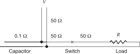
For a two-terminal capacitor, energy must enter and leave through the same port. When a load is applied to this geometry, energy is supplied to the load from the capacitor and from any connecting transmission lines (traces). This includes logic lines connected in the IC. The majority of the energy eventually comes from the capacitor. After the load is connected, waves travel into the capacitor and onto any other connecting transmission lines. The wave that travels into the capacitor, reflects at the open end and brings back energy to the load.2 The wave(s) that follows the connecting trace(s) reflect at branch points also bring back energy to the load and to the capacitor. One of the paths can connect to the ground/power plane capacitance. This complex of wave actions replenishes the charge in the capacitor.
Any resupply of energy to the capacitor must come from multiple reflections on traces with a nominal characteristic impedance of 50 ohm. Even if the capacitor is parallel connected to the ground/power plane capacitance, this energy must flow through a connection (vias) that also have a characteristic impedance of approximately 50 ohm. As we have seen, waves must make multiple round trips through the vias to supply the required energy. Obtaining energy has a time constant that depends on transmission line lengths and characteristic impedances.
The analogy with a water reservoir is appropriate. The water that is supplied to a reservoir does not use the exit conduit. This water always enters through a separate port. Even though a conduit is a two-way device it is futile to try to force water to flow in both directions at the same time. This is exactly what we attempt to do when we draw energy from a capacitor, and at the same time try to put it back through the same two terminals.
Capacitors are often constructed using stacked conducting layers. This design approach is an effective way to increase the capacitance in a small volume. The problem with this construction is that the inner layers can be blocked from receiving energy by the parallel connections at the ends of the capacitor. The energy that enters or leaves these layers of the capacitor must use the air space around the sides of the capacitor. In a circuit sense, this has the effect of raising the entry inductance.