
3.8 The Cross Coupling Process (Cross Talk)
The cross coupling process is complicated, because there are so many cases to consider.
Logic can be carried in either direction on any one line. Logic can be carried in the same or in opposite directions on parallel lines. Culprit lines can be longer or shorter than victim lines. Lines can be series or parallel terminated. Lines can be unterminated, which causes voltage doubling. Coupling on microstrip is different than coupling on stripline. Cross coupling depends on the logic family where there are different error margins.
The language of cross coupling has evolved with time. In radio transmission, terms such as far-end and near-end cross coupling are used. Interference acronyms such as FEXT for far-end cross coupling and NEXT for near-end cross coupling are used.
Cross coupling can be considered to have inductive and capacitive components with waves traveling in both directions. We will refer to forward coupling when the coupled signal travels in the same direction as the driving or culprit wave. Reverse coupling implies that the coupled signal travels in a direction opposite to the driving or culprit wave.
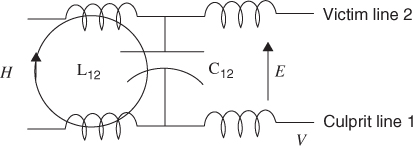
The cross coupling process between parallel transmission lines can be analyzed by assuming that the lumped parameter elements that make up a transmission line are loosely coupled. This assumption allows us to separate the coupling mechanism into capacitive and inductive components. The representation in Figure 3.6 shows two traces over a ground plane. One of the lines is the victim and the other is the culprit.
Figure 3.6 The mutual inductance and mutual capacitance coupling in parallel transmission lines. Note: Transmission lines are over a ground plane.
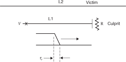
When a logic voltage is switched on the culprit line L1, a wave propagates to the right. Note that in our preliminary discussion, the victim line L2 is longer than line L1. This allows us to discuss reverse coupling without having a nearby reflection point on the victim line. A culprit step function with a finite rise time is shown in Figure 3.7.
Figure 3.7 A step function wave applied to the culprit line.
The coupling process involves both mutual inductance and mutual capacitance. We must equate the changing H field that is present in the inductance of L1 to a changing current and the changing E field that is present in the line capacitance to be a changing voltage. There is no loss in generality if we limit our discussion to a positive culprit wave that travels to the right. To start the discussion we will not consider terminations or reflections on the victim line.