3.8. USE OF DIFFERENTIAL EQUATIONS OF CONTINUITY AND MOTION
3.8A. Introduction
The purpose and uses of the differential equations of motion and continuity, as mentioned previously, are to apply these equations to any viscous-flow problem. For a given specific problem, the terms that are zero or near zero are simply discarded and the remaining equations used to solve for the velocity, density, and pressure distributions. Of course, it is necessary to know the initial conditions and the boundary conditions to solve the equations. Several examples will be given to illustrate the general methods used.
We will consider cases for flow in specific geometries that can easily be described mathematically, such as flow between parallel plates and in cylinders.
3.8B. Differential Equations of Continuity and Motion for Flow between Parallel Plates
Two examples will be considered, one for horizontal plates and one for vertical plates.
EXAMPLE 3.8-1. Laminar Flow Between Horizontal Parallel PlatesDerive the equation giving the velocity distribution at steady state for laminar flow of a constant-density fluid with constant viscosity flowing between two flat and parallel plates. The velocity profile desired is at a point far from the inlet or outlet of the channel. The two plates will be considered to be fixed and of infinite width, with the flow driven by the pressure gradient in the x direction. Solution: Assuming that the channel is horizontal, Fig. 3.8-1 shows the axes selected, with flow in the x direction and the width in the z direction. The velocities νy and νz are then zero. The plates are a distance 2y0 apart. Figure 3.8-1. Flow between two parallel plates in Example 3.8-1.
The continuity equation (3.6-24) for constant density is Equation 3.6-24
Since νy and νz are zero, Eq. (3.6-24) becomes Equation 3.8-1
The Navier-Stokes equation for the x component is Equation 3.7-36 Also, ∂νx/∂t = 0 for steady state, νy = 0, νz = 0, ∂ νx/∂x = 0, ∂2νx/∂x2 = 0. We can see that ∂νx/∂z = 0, since there is no change of νx with z. Then ∂2νx/∂z2 = 0. Making these substitutions into Eq. (3.7-36), we obtain Equation 3.8-2
In fluid-flow problems we will be concerned with gravitational force only in the vertical direction for gx, which is g, the gravitational force, in m/s2. We shall combine the static pressure p and the gravitational force and call them simply p, as follows (note that gx = 0 for the present case of a horizontal pipe but is not zero for the general case of a nonhorizontal pipe): Equation 3.8-3
where h is the distance upward from any chosen reference plane (h is in the direction opposed to gravity). Then Eq. (3.8-2) becomes Equation 3.8-4
We can see that p is not a function of z. Also, assuming that 2y0 is small, p is not a function of y. (Some references avoid this problem and simply use p as a dynamic pressure, which is rigorously correct since dynamic pressure gradients cause flow. In a fluid at rest, the total pressure gradient is the hydrostatic pressure gradient, and the dynamic pressure gradient is zero.) Also, ∂p/∂x is a constant in this problem, since νx is not a function of x. Then Eq. (3.8-4) becomes an ordinary differential equation: Equation 3.8-5
Integrating Eq. (3.8-5) once, using the condition dνx/dy = 0 at y = 0 for symmetry, Equation 3.8-6
Integrating again, using νx = 0 at y = y0, Equation 3.8-7
The maximum velocity in Eq. (3.8-7) occurs when y = 0, giving Equation 3.8-8
Combining Eqs. (3.8-7) and (3.8-8), Equation 3.8-9
Hence, a parabolic velocity profile is obtained. This result was also obtained in Eq. (2.9-9) when using a shell-momentum balance. |
The results obtained in Example 3.8-1 could also have been obtained by making a force balance on a differential element of fluid and using the symmetry of the system to omit certain terms.
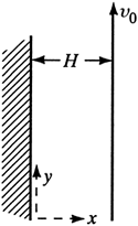
EXAMPLE 3.8-2. Laminar Flow Between Vertical Plates with One Plate MovingA Newtonian fluid is confined between two parallel and vertical plates as shown in Fig. 3.8-2 (W6). The surface on the left is stationary and the other is moving vertically at a constant velocity ν0. Assuming that the flow is laminar, solve for the velocity profile. Figure 3.8-2. Flow between vertical parallel plates in Example 3.8-2.
Solution: The equation to use is the Navier-Stokes equation for the y coordinate, Eq. (3.7-37): Equation 3.7-37
At steady state, ∂νy/∂t = 0. The velocities νx and νz = 0. Also, ∂νy/∂y = 0 from the continuity equation, ∂νy/∂z = 0, and ρgy = -ρg. The partial derivatives become derivatives and Eq. (3.7-37) becomes Equation 3.8-10
This is similar to Eq. (3.8-2) in Example 3.8-1. The pressure gradient dp/dy is constant. Integrating Eq. (3.8-10) once yields Equation 3.8-11
Integrating again gives Equation 3.8-12
The boundary conditions are at x = 0, νy = 0 and at x = H, νy = ν0. Solving for the constants, C1 = ν0/H - (H/2μ)(dp/dy + ρg) and C2 = 0. Hence, Eq. (3.8-12) becomes Equation 3.8-13
|
3.8C. Differential Equations of Continuity and Motion for Flow in Stationary and Rotating Cylinders
Several examples will be given for flow in stationary and rotating cylinders.
EXAMPLE 3.8-3. Laminar Flow in a Circular TubeDerive the equation for steady-state viscous flow in a horizontal tube of radius r0, where the fluid is far from the tube inlet. The fluid is incompressible and μ is a constant. The flow is driven in one direction by a constant-pressure gradient. Solution: The fluid will be assumed to flow in the z direction in the tube, as shown in Fig. 3.8-3. The y direction is vertical and the x direction horizontal. Since νx and νy are zero, the continuity equation becomes ∂vz/∂z = 0. For steady state ∂vz/∂t = 0. Then substituting into Eq. (3.7-38) for the z component, we obtain Equation 3.8-14
Figure 3.8-3. Horizontal flow in a tube in Example 3.8-3.
To solve Eq. (3.8-14), we can use cylindrical coordinates from Eq. (3.6-26), giving Equation 3.6-26
Substituting these into Eq. (3.8-14), Equation 3.8-15
The flow is symmetrical about the z axis, so ∂2νz/∂θ2 is zero in Eq. (3.8-15). As before, dp/dz is a constant, and Eq. (3.8-15) becomes Equation 3.8-16
Alternatively, Eq. (3.7-42) in cylindrical coordinates can be used for the z component and the terms that are zero discarded: Equation 3.7-42
As before, ∂νz/∂t = 0, ∂2νz/∂θ2 = 0, νr = 0, ∂vz/∂θ = 0, ∂νz/∂z = 0. Then Eq. (3.7-42) becomes identical to Eq. (3.8-16). The boundary conditions for the first integration are dνz/dr = 0 at r = 0. For the second integration, νz = 0 at r = r0 (tube radius). The result is Equation 3.8-17
Converting to the maximum velocity as before, Equation 3.8-18
If Eq. (3.8-17) is integrated over the pipe cross section using Eq. (2.9-10) to give the average velocity νz av, Equation 3.8-19
Integrating to obtain the pressure drop from z = 0 for p = p1 to z = L for p = p2, we obtain Equation 3.8-20
where D = 2r0. This is the Hagen-Poiseuille equation, derived previously as Eq. (2.9-11). |
EXAMPLE 3.8-4. Laminar Flow in a Cylindrical AnnulusDerive the equation for steady-state laminar flow inside the annulus between two concentric horizontal pipes. This type of flow occurs often in concentric-pipe heat exchangers. Solution: In this case Eq. (3.8-16) also still holds. However, the velocity in the annulus will reach a maximum at some radius r = rmax which is between r1 and r2, as shown in Fig. 3.8-4. For the first integration of Eq. (3.8-16), the boundary conditions are dνz/dr = 0 at r = rmax, which gives Equation 3.8-21
Figure 3.8-4. Flow through a cylindrical annulus.
Also, for the second integration of Eq. (3.8-21), νz = 0 at the inner wall where r = r1, giving Equation 3.8-22
Repeating the second integration but for νz = 0 at the outer wall where r = r2, we obtain Equation 3.8-23
Combining Eqs. (3.8-22) and (3.8-23) and solving for rmax, Equation 3.8-24
In Fig. 3.8-4 the velocity profile predicted by Eq. (3.8-23) is plotted. For the case where r1 = 0, rmax in Eq. (3.8-24) becomes zero and Eq. (3.8-23) reduces to Eq. (3.8-17) for a single circular pipe. |
EXAMPLE 3.8-5. Velocity Distribution for Flow Between Coaxial CylindersTangential laminar flow of a Newtonian fluid with constant density is occurring between two vertical coaxial cylinders in which the outer one is rotating (S4) with an angular velocity of ω, as shown in Fig. 3.8-5. It can be assumed that end effects can be neglected. Determine the velocity and the shear-stress distributions for this flow. Figure 3.8-5. Laminar flow in the region between two coaxial cylinders in Example 3.8-5.
Solution: On physical grounds the fluid moves in a circular motion; the velocity νr in the radial direction is zero and νz in the axial direction is zero. Also, ∂ρ/∂t = 0 at steady state. There is no pressure gradient in the θ direction. The equation of continuity in cylindrical coordinates as derived before is Equation 3.6-27
All terms in this equation are zero. The equations of motion in cylindrical coordinates, Eqs. (3.7-40), (3.7-41), and (3.7-42), reduce to the following, respectively: Equation 3.8-25
Equation 3.8-26
Equation 3.8-27
Integrating Eq. (3.8-26), Equation 3.8-28
To solve for the integration constants C1 and C2, the following boundary conditions are used: at r = R1, νθ = 0; at r = R2, νθ = ωR2. The final equation is Equation 3.8-29
Using the shear-stress component for Newtonian fluids in cylindrical coordinates, Equation 3.7-31
The last term in Eq. (3.7-31) is zero. Substituting Eq. (3.8-29) into (3.7-31) and differentiating gives Equation 3.8-30
The torque T that is necessary to rotate the outer cylinder is the product of the force times the lever arm: Equation 3.8-31
where H is the length of the cylinder. This type of device has been used to measure fluid viscosities from observations of angular velocities and torque and has also been used as a model for some friction bearings. |
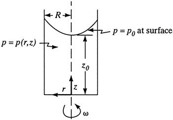
EXAMPLE 3.8-6. Rotating Liquid in a Cylindrical ContainerA Newtonian fluid of constant density is in a vertical cylinder of radius R (Fig. 3.8-6) with the cylinder rotating about its axis at angular velocity ω (B2). Find the shape of the free surface at steady state. Figure 3.8-6. Liquid being rotated in a container with a free surface in Example 3.8-6.
Solution: The system can be described in cylindrical coordinates. As in Example 3.8-5, at steady state, νr = νz = 0 and gr = gθ = 0. The final equations in cylindrical coordinates given below are the same as Eqs. (3.8-25)-(3.8-27) for Example 3.8-5, except that gz = -g in Eq. (3.8-27): Equation 3.8-32
Equation 3.8-33
Equation 3.8-34
Integration of Eq. (3.8-33) gives the same equation as in Example 3.8-5: Equation 3.8-28
The constant C2 must be zero since νθ cannot be infinite at r = 0. At r = R, the velocity νθ = Rω. Hence, C1 = ω and we obtain Equation 3.8-35
Combining Eqs. (3.8-35) and (3.8-32), Equation 3.8-36
Hence, we see that Eqs. (3.8-36) and (3.8-34) show that pressure depends upon r because of the centrifugal force and upon z because of the gravitational force: Equation 3.8-34
Since the term p is a function of position, we can write the total differential of pressure as Equation 3.8-37
Combining Eqs. (3.8-34) and (3.8-36) with (3.8-37) and integrating, Equation 3.8-38
The constant of integration can be determined, since p = p0 at r = 0 and z = z0. The equation becomes Equation 3.8-39
The free surface consists of all points on this surface at p = p0. Hence, Equation 3.8-40
This shows that the free surface is in the shape of a parabola. |


