
Chapter 6. Application Partitioning
So we grew together, Like to a double cherry, seeming parted, But yet a union in partition; Two lovely berries moulded on one stem.
—Shakespeare, A Midsummer Night’s Dream
If you destroy a bridge, be sure you can swim.
—Swahili proverb
In 1987 the author took his first formal training course in an OOA/D methodology. The first diagram described the large-scale, logical partitioning of the application, which today is known as a UML Component diagram. The instructor was asked how much time should be spent on the diagram. His answer was, “If you spend half a day, that is probably too long.” That was the single worst piece of technical advice the author ever received. For a large application, that activity is the single most important activity in the entire development process.
Why Do We Care?
Every complex software application has a basic architecture that represents the structure or skeleton of the application. That structure provides a framework for the rest of the design elements. The framework acts very much like a back plane in electronic equipment that enables different modules to communicate in a disciplined way. That framework also supports plug-and-play for large-scale reuse.
Application partitioning organizes the application.
The essential work of application partitioning is to subdivide the application logically into subsystem modules. That organization necessarily affects how we think about individual subsystems when we design them. It also affects how we think about the way they will communicate with one another. Finally, and probably most important, it affects the way we allocate and isolate customer requirements within the application. If that organization changes, then it is quite likely that change will trigger a lot of rework in each subsystem. This is because those subsystems were built with particular assumptions about the way the application was organized. If those assumptions are no longer correct, then it is likely that fundamental changes will have to be made to the way each of those subsystems works.
Maintainability depends on a stable underlying structure.
Maintainable applications all share certain characteristics.
• The location of change is readily recognized.
• The scope of change is limited.
• The complexity of change is limited.
Application partitioning directly addresses the first two. The OO paradigm as a whole addresses the last characteristic by making detailed designs easier to modify. A change takes place in the subsystem defined to “own” the relevant requirements. (As we shall see shortly, client/service relationships explicitly allocate specific requirements to subsystems.) If subsystems are cohesive and subsystem boundaries are well-defined, then change will tend to be isolated within one or a few subsystems. However, change location is only recognized easily, and the scope of change is only limited if the organization of the subsystems—particularly their definitions—are stable over the life of the application. If the basic definition of the application structure is a moving target, then it is simply not possible to deliver on maintainability goals.
The OO paradigm and MBD in particular provide a systematic approach to application partitioning that will ensure long-term stability of the application structure. Better yet, it is a fundamentally intuitive methodology. So, the bad advice cited in the chapter opening was half right; once you get the hang of it, properly partitioning even the largest applications is usually measured in tens of hours and for a smallish application, half a day may be appropriate. The problem with the advice was that it didn’t get across the idea that we absolutely need to take whatever time is necessary to get it right.
It is not possible to overemphasize how important partitioning is. The author worked on a large application with nearly two dozen subsystems where not a single subsystem’s definition changed during more than a decade of heavy maintenance. Subsystems were added for new functionality and their implementations were modified, but the original definitions of subject matters and levels of abstraction remained unchanged. That sort of semantic stability is enormously valuable over the life of an MLOC+ application.
It was a hardware control system for a large electronics tester (~10K control registers) capable of testing every digital component on something like a B-52 bomber. During that decade the underlying hardware was redesigned several times; not a single card in the system when the author retired had existed when the software was originally developed. Large chunks of functionality, such as diagnostics algorithms, were added on a plug-and-play basis. Over time it was run from a Wintel GUI, a Unix remote client, a customer’s C program, an ATLAS test IDE, and as a component of a larger test system. There was a ton of maintenance done, and the final system was integer factors larger than the original. Yet after the first year of original development it was maintained by no more than four developers and usually only one developer, half-time. Many developers maintaining large R-T/E systems would kill to be able to work on something that stable.
Basic Concepts of Application Partitioning
Application partitioning is fundamentally a systems engineering task for large applications. Many OOA/D books do not even mention it because systems engineering is often viewed as a different trade union from OO development. However, the OO paradigm focuses on problem space abstraction, a very useful tool when trying to partition a large application for maintainability. That, combined with the importance of good partitioning, is why this is one of the largest chapters in the book.
As the last chapter indicated, invariants in the problem space should be ubiquitous in the design at all scales. The application structure will only have long-term stability if it is based on problem space invariants. Invariants ensure that the cohesion of the partitions is unlikely to change over the long term. When subsystem interfaces are defined in terms of invariants, that provides long-term decoupling of the subsystem implementations. That, in turn, prevents architectural drift as those subsystem implementations are modified during maintenance.1
There are a number of specific ways that good partitioning improves maintainability. It is essential to understand that context in terms of why good partitioning is important and how it helps maintainability.
Cohesion. Cohesion is important because it helps to isolate change to the implementations encapsulated within one or a few interfaces. In addition, good cohesion facilitates good interfaces and mitigates against redundancy of function.
Interfaces. Strong interfaces enhance testability because they enable partitions to be tested on a stand-alone basis. They also enhance communications among different teams on large projects because they can be generalized and documented before the implementation is actually designed. On large projects they become the primary vehicle of communication for teams working on different subsystems. Once the requirements are allocated and the interfaces are negotiated, the developers of the individual subsystems can go their separate ways.2
Implementation hiding. Strong interfaces decouple clients from the niggling details of specific implementations. Since the details are the things most likely to change, strong interfaces tend to limit the scope of change through encapsulation.
Problem space abstraction. Good partitioning maps large-scale application structure into familiar customer infrastructure. Since customers accommodate change in a manner that causes the least disruption to their existing major structures, the major software structures will be minimally affected.
Invariants. Mapping partition boundaries against conceptual boundaries in the customer’s environment that are unlikely to change will tend to provide long-term stability for the application framework.
Client/Service relationships. If partitioning reflects true client/service relationships, this effectively manages dependencies so that they form an acyclic directed graph. Any software engineering theoretician will be happy to give you twenty minutes on why acyclic directed graphs are good things.
If these points sound familiar, they should. The first five are pretty much the OO paradigm’s central view of what class abstractions are about. As it happens, MBD treats application partitions almost exactly as if they were really big objects. The last point is just a well-established technique for managing software complexity.3
We need to take time out for a definition of our basic unit of large-scale encapsulation. Essentially the UML semantics are paraphrased in MBD as follows:
A subsystem is a large-scale logical unit of the software that abstracts a cohesive problem space subject matter at a particular level of abstraction and encapsulates that subject matter behind an interface.
This definition captures most of the critical ideas behind application partitioning. Application partitioning is about defining subsystems, and the MBD methodology addresses four activities in doing that: identifying subject matters, identifying levels of abstraction, defining interfaces, and allocating requirements. The rest of this chapter summarizes each of these activities.
Subject Matter
A subsystem is a part of the application that implements a unique subject matter. As indicated previously, the basic MBD view of a subsystem is that it is an object on steroids. More specifically, it has the following characteristics.
• It is an abstraction of an invariant problem space entity, usually conceptual.
• It encapsulates a subject matter that addresses a unique suite of functional requirements.
• It is logically cohesive.
• It has an intrinsic suite of knowledge and behaviors for which it is responsible.
• Its implementation is hidden.
• It is encapsulated behind a pure message (event) interface.
• Its behavior is functionally isolated (i.e., it is not directly dependent on other subsystems’ behaviors).
• It is uniquely identified.
The MBD view of a subsystem is even more constrained than an object because the interface used to encapsulate it provides more decoupling than a class interface.
The implementation of a subsystem is almost always done with objects. (Alternatively, we can nest subsystems to provide decomposition in very large systems.) The implementation of a subsystem is a set of objects that interact directly with one another. This is an important concept for MBD because it brings new meaning to the notion of implementation hiding.
The objects that implement a subsystem should be hidden from other subsystems.
This makes a lot of sense if we think about it for a moment and allow for the switch in implementation scale. Yet it is a notion that is very rarely expounded in OO books. As a result, we see lots of OO applications where problem space object references are passed routinely all over the application. Those references expose the implementation of some part of the application to the rest of the application because they were abstracted to implement the source subsystem. Not only do they introduce dependencies in the rest of the application on that specific implementation, they also give the rest of the application a license to kill (i.e., blow the sender implementation away).
A good example of why references should not be passed is the ubiquitous window handle in GUI applications. Often these applications will pass window handles all over the application. Since the OS Window Manager can be accessed from anywhere in the application, virtually anybody can update the GUI directly. Then the developers lament that porting their applications to a different platform with a different Window Manager is a big problem! In MBD, one and only one subsystem would have a subject matter that was responsible for GUI display, and any time another subsystem needed something displayed, it would talk to that subsystem rather than to the OS Window Manager directly.
The critical methodological ideas that affect design of subsystems are the following:
• Subject matters are unique. A particular suite of problem space rules and policies should only be found in a single subsystem.
• Subject matters are cohesive. The responsibilities are logically related in the problem space. A corollary is that the requirements to be addressed in the subsystem design are narrowly defined.
• Subsystems are self-contained. The design of a particular subsystem can be done in complete isolation from any other subsystem. A subsystem can be fully tested functionally in complete isolation (in effect, a unit test on steroids).
• The overall semantics of the subject matter (i.e., what it is) are invariant. The details may change, but its role in the overall problem solution context does not change.
When identifying subject matters, the most important consideration is the problem space. Whatever you identify as a subsystem should be readily identifiable in the problem space.4 The application partitions should always be validated with the relevant customers. For all but the largest systems we are talking on the order of a dozen subsystems, so validation shouldn’t be a major problem. There are a couple of key questions for that validation.
Does a domain expert recognize it immediately? The name of the partition should immediately evoke some perception of what the partition is about. If that perception doesn’t line up reasonably well with your view, you have a problem.
Does a domain expert agree with the subject matter description? This is not absolutely essential at the nit level because it is in the nature of abstraction to make compromises with reality. But when summarizing the essence of a subsystem in a few sentences, the domain expert needs to keep nodding in the affirmative when reading them.
The last question is worth further qualification. Subsystem descriptions are done in natural language and, therefore, they are imprecise and ambiguous. Also, people provide their own filters based upon their psychological set, past experience, and preconceptions.
The value of subsystem descriptions is much more important for gaining consensus than for documenting the application.
The customer provides the requirements and you are going to have to allocate them to subsystems. You will find that a lot easier to do if you and the customer share exactly the same semantic view of the subsystems. This is because the customer thinks about and organizes requirements within the context of the problem space. If your application organization lines up with the customer’s problem space organization, you are providing a customer-friendly environment for those requirements. If nothing else, scrubbing the subsystem descriptions with the customer will provide added insight into the requirements themselves.
It is beyond the scope of this book to get into detailed scrubbing techniques for natural language. The literature of both requirements elicitation and process improvement provides a wealth of material on this. I will only say that it is very important that you encourage detailed feedback on the descriptions. If you have never participated in formal consensus-gathering techniques (e.g., KJ diagrams5) you will be amazed at how much insight can be gathered and how many surprises there can be when people begin to discuss how they actually interpret written words.
As an example, consider a garage door opener. There will be a basic application subsystem, say Opener, that will contain the high-level logic for opening and closing the garage door. To do that it will have to send and/or receive events from a clicker, a drive motor, and an electric eye. Each of these hardware components is quite different with clearly different responsibilities, so we could separate them out into separate subsystems as in Figure 6-1(a).
Figure 6-1. Alternative component diagrams for a garage door opener
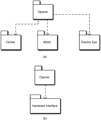
On the other hand, we can make a case that the garage door opener software is about controlling hardware. That is, we could consider a single hardware subsystem dedicated to detailed register reads/writes for controlling the door motion. In that case we could combine talking to the individual hardware components into a single Hardware Interface subsystem, as in Figure 6-1(b).
So which would have greater clarity and cohesion? The answer, Grasshopper, is clearly: both. Which one is best will depend upon other information in the application problem domain. For example, suppose each hardware component comes with a software device driver from the hardware vendor and you don’t plan to do a lot of hardware swapping. Those device drivers will be separate, realized components. The interface to them will be trivial; the total code lines to talk to those drivers might be a dozen function calls. In that case, you will probably want to go with Hardware Interface because the distinction between hardware components is largely transparent to the analysis.
Now suppose you have to provide a device driver doing direct register reads and writes for each hardware component, and you will have several different models with different vendor hardware components. Then you may want separate subsystems even though they may be pretty small. The resulting design of the individual drivers will be significant, and it will have to be conveniently managed. The need for plug-and-play is an important requirement that justifies explicit isolation of the design for individual hardware components. Thus, clarity and cohesion are relative to the application context.
But what about reuse? If we define subsystems based on particular application contexts, won’t that interfere with reuse? Yes, it might. But software development is full of trade-offs. Since you brought it up, though, the version in Figure 6-1(a) is likely to be better for reuse. Why? Because individual drivers can be readily substituted. We can probably come up with a very generic interface for each driver that will enable the implementations to be swapped transparently behind it. The Hardware Interface in Figurer 6-1(b) must necessarily coordinate specific drivers (i.e., make exactly the right driver calls). If we start to substitute drivers we could end up with a combinatorial number of Hardware Interface subsystem implementations.
Client/Service Relationships
Since subsystems embody functional subject matters, each subsystem must address some set of customer requirements. Good cohesion demands that the particular set of requirements that a subsystem resolves must be unique. (When large-scale customer requirements span subsystems, they are broken up into finer-grained requirements that can be individually allocated to particular subject matters, typically by a systems engineer.) In MBD, we do this by organizing subsystems in a directed, acyclic graph of client/service relationships or dependencies. Those relationships represent a flow of requirements from a client to a service.
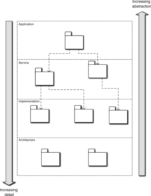
At the top of the component diagram we usually have a single subsystem that provides overall high-level control over the problem solution. At the bottom will be very detailed and highly specialized services, so the graph forms an inverted tree. The level of abstraction is very high at the top and very low at the bottom. Reuse tends to increase as we move down the graph because detailed supporting services tend to be more generic (i.e., they apply to entire classes of similar problems). This is demonstrated schematically in Figure 6-2. The diagram groups subsystems into four broad categories: Application, which are very problem specific; Services, which are application specific but may provide reuse for very similar problems; Implementation, which tend to be highly reusable implementations of common facilities like database access; and Architecture, which represent placeholders for infrastructure like particular technologies. The Architecture group simply identifies computing space infrastructure the other subsystems will use, such as a particular operating system, so we usually don’t clutter the diagram with dependencies to the Architectural subsystems.
Figure 6-2. Layout of Subsystem Component diagram
It is important not to confuse this with communication. Communications can flow in either direction. For example, most applications will have a low-level service subsystem, the sole purpose of which is to communicate with the software user in a particular UI paradigm (e.g., GUI or web browser). The requirements on that subsystem—the semantics of what it needs to communicate—will be driven by the other subsystems in the problem solution that will need to communicate with the user. However, since the user is actually running the solution, most of the communications—the individual messages—will originate interactively with the user. Thus, requirements flow down from the problem solution while communication flows up from the user.
This architecture fundamentally influences the way we think about design, particularly for subsystem interfaces. Allocating requirements to subject matters using client/service relations requires a DbC contract between client and service. That contract will be manifested in the interface provided by the service, and the interface will reflect the invariants about how the service is used. The subsystem design then needs to directly support that interface. The client/service perspective combines with DbC and invariants to overlay a very SOA-like6 mindset on application structure and the design of low-level service subsystems.
Levels of Abstraction
Every subsystem is defined at a particular level of abstraction. When large subject matters are broken up to make them more manageable for a large project, that is invariably done by defining at least two different levels of abstraction: high-level control and low-level grunt work.
The level of abstraction of a subsystem is profoundly important to the design of the abstractions that implement the subsystem. All the objects of a subsystem will be at the same level of abstraction. This is the principal way that the OO paradigm deals with the flexible notion of logical indivisibility discussed in Chapter 2. This enables us to hide details and deal with the big picture in high-level subsystems while relegating details to lower-level service subsystems that are relatively myopic.
As an example, consider an application that solves different types of problems by applying the appropriate algorithms, as indicated in Figure 6-3. To do this it has to get instructions from the user, acquire data, select the best solution, execute the solution, and report the results; this quite clearly describes the steps in a high-level solution without mentioning anything specific about the details of individual steps. The solution has been abstracted so that we can delegate the grunt work for each of the steps to service subsystems. This is the central idea behind using abstraction to partition the application.
Figure 6-3. Component diagram for a mathematics application
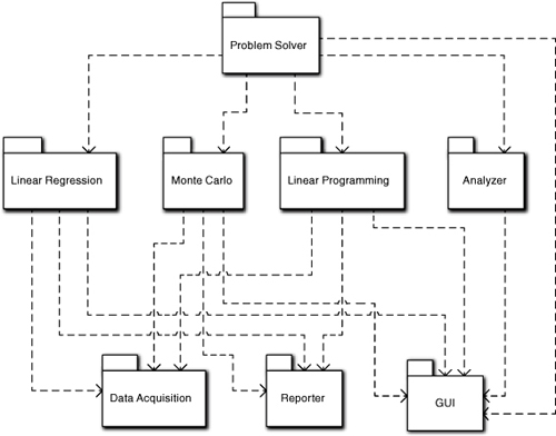
Similarly, the previous description dismissed things like data acquisition, reporting, and the UI as clauses in passing, despite that there might be thousands of LOC behind those subject matters. That’s because they involve very detailed, pedestrian, and highly reusable processing. While selecting algorithms and implementing complex mathematics efficiently requires a certain creative flair, this sort of processing is highly standardized minutia that even entry-level developers can do in their sleep. Thus we have three broad levels of abstraction: overall coordination, complex analysis and algorithmic processing, and supporting grunt work.
Thus in Figure 6-3 the highest-level subsystem, Problem Solver, invokes the GUI subsystem to get user information, then invokes Data Acquisition to collect any data, then invokes Analyzer to select the best algorithm, and then invokes the proper algorithm. We can describe that without knowing anything about the details. Problem Solver’s mission in life then is to manage that sequence, not the actual activities.
Within Problem Solver we might abstract a Linear Program object that is a surrogate for a linear programming algorithm. At the level of abstraction of Problem Solver, that Linear Program object just represents a proxy for the actual algorithm. It might have interface methods like Initialize, Solve, and Report. Those methods would simply navigate the relationship to the actual algorithm.
Now we could include a flock of objects like Matrix in Problem Solver that would collaborate with the Linear Programming algorithm to actually solve the problem. After all, this application is about solving problems, and Problem Solver is the main subsystem to do that, right? Intuitively one can figure out that this would probably be a bad idea even without MBD or the OO paradigm. It would make Problem Solver hopelessly complex and obscure the high-level processing of selection, acquisition, execution, and reporting. The surrogate object in Problem Solver abstracts that away while still describing what is going on. Similarly, just looking at the names in Figure 6-3 gives us a warm and fuzzy feeling about separation of concerns and having a good handle on the big picture.
Interfaces
Every subsystem has an interface. These are also known as bridges in the translation community. This is because subsystem dependencies are different from object relationships, and they will be handled differently by a transformation engine. One unique thing about bridges is that they are two-way; the notion of a bridge refers to two pairs of input/output interfaces that talk to each other. When a subsystem’s implementation needs to send a message to the outside world, it sends it to the subsystem’s output interface. That output interface then forwards the message to the receiver system’s input interface.
The reason we use subsystem interfaces is to minimize coupling and support large-scale reuse. However, the bane of reuse is syntactic mismatches, which we will talk about shortly. Two-way interfaces provide a mechanism to deal with syntactic mismatches.
In MBD these bridges are highly disciplined to ensure a high degree of decoupling. (Some translationists liken them to firewalls between subsystem implementations.) They are pure message interfaces: {message ID, [by-value data packet]}. In fact, MBD subsystem interfaces are almost invariably event based.
These are the critical things important to the later chapters.
• The nature of the bridge is two-way, where the sender of a message talks to its own output interface rather than directly to the input interface of the receiving subsystem.
• Messages are very basic communications. This often requires communications to be more fine-grained than we might have if we could pass objects or access behavior remotely.
• Inevitably, messages between subsystems require some sort of encoding and decoding by sender and receiver, respectively. This is the price of decoupling so militant that the only things shared by the subsystems are the structure and identity of the messages themselves.
• The communication model is always the more general asynchronous model. This usually implies some sort of handshaking protocols that must be incorporated in the subsystem design.
While bridges are highly constrained and those constraints must be honored in subsystem implementations, they provide huge benefits in efficiency, robustness, maintainability, and large-scale reuse.
Identifying Subsystems
Identifying subsystems is primarily an exercise in problem space abstraction. In fact, it is really the purest and simplest form of problem space abstraction because we are focused exclusively on large-scale structure in the problem space. There are no hard and fast rules for partitioning applications, but answering the following questions about candidate subsystems can be very useful. Basically, we seek insight into why the candidate subsystem in hand is different from others.
When abstracting the same entities as other subsystems, does the subsystem in hand have a different view of them?
This is critical for problem space entities.7 Different subject matters have different rules and policies (behavior responsibilities), so entities in different subsystems should reflect that. We will tailor the object abstractions to the subject matter in hand to keep them simple within a subsystem. Since different subsystems do different things, we would have different views or tailorings of those entities when we abstract them as objects in our solution.
Is there a client/service relationship?
For this we need some definitions:
Client: A participant in a one-way, binary collaboration that requests the professional services of the other participant
Service: A participant in a one-way, binary collaboration that provides professional services to the other participant
Thus the client/service relationship just says that there is some collaboration context where one subsystem provides a service for another subsystem. That other subsystem becomes the client, and it defines requirements for the service to be provided.
To reiterate a point made earlier, this is not about communication; it is about requirements flows. In particular, it is about the nature of the subject matters and their role in the overall solution. We design our OO subsystems so that when a specific message is sent during a collaboration, there is no expectation by the object sending the message about what will happen as a result; the message simply announces something the sender did. That is, the object sending the message is part of the implementation for the subsystem and knows nothing about external context; it is just communicating. So it has no idea whether the subsystem containing it is a client or a service in the collaboration context. The client/service “expectation” exists in the mind of the systems engineer partitioning the application for solving the overall problem.
Is the service more detailed than the client?
This is about the level of abstraction rather than the amount of detail. In the Problem Solver example earlier in the chapter, the actual algorithms could involve thousands of LOC while something like Data Acquisition might be a fairly trivial reading of file records and dumping values into memory arrays. The fact that Data Acquisition could be “cookbook” processing—it is very narrowly defined, largely independent of the implications of the data semantics for the problem, and clearly a supporting service—is what determines it as a low-level, detailed service at a lower level of abstraction, not the amount or complexity of processing.
Is knowledge shared with other subsystems?
What we are after here are the public knowledge responsibilities of the subsystem itself. The subsystem has responsibilities that are defined by its interface. Generally, it is a good idea for there to be a single “owner” subsystem for knowledge among subsystems.8 When objects implementing different subsystems do share data, we need to make sure that data is used in different ways in those subsystems.
Is behavior shared with other subsystems?
Here we are focused on the public responsibilities of the subsystem, as reflected in its interface. While shared knowledge is sometimes forgivable, shared behavior is grounds for burning the developer at the stake. Subject matters should resolve unique sets of functional requirements, and functional requirements define what the software solution must do. Therefore, what a subject matter does should always be unique.
Is the subject matter cohesive?
A subject matter is associated with what an identifiable problem space entity is. The nature of something is a bundle of logically related properties from an OO perspective, so the subsystem’s knowledge and behavior responsibilities should be logically cohesive and intrinsic to the entity. Thus,
Customer domains define cohesion, not developers.
Is the boundary clearly defined?
This is of critical importance to long-term stability. In an ideal world we want our subsystems to be defined so that it is obvious where customer requirements need to be resolved. Equally important, we do not want that to be a moving target over time. Ultimately that is up to the domain experts, so it is critical to scrub our subject matter definitions with them.
Unfortunately, our world is rarely ideal, and sometimes it will be difficult to gain consensus among domain experts. While gaining consensus up front on the way the problem domain should work can be painful, it will pay huge benefits over the life of the product.9
Could it be reused as-is?
While we focus on the problem in hand, the practical realities of software development force us to evaluate potential reuse from the perspective of the software shop’s overall productivity. Fortunately, the way we define subject matters will almost always foster reuse. When we define subject matters and their interfaces in terms of invariants, that comes pretty much for free.
Is it bounded by a network in a distributed environment?
Technically this is a pure OOP issue and should not affect the OOA/D. In addition, like reuse, we generally get convenient distributed boundaries pretty much for free when we identify subject matters carefully. So this question is really a kind of sanity check. If you think a distributed boundary is going to go through the middle of your subject matter, it is almost certain you screwed something up.
Is it a different problem space?
As you will recall, an application can deal with multiple distinct problem spaces. Many of the guidelines above can be expressed in terms of identifying distinct problem spaces because a problem space is, by definition, a unique subject matter. So this is just a high-level criterion for recognizing a subject matter. When thinking about subject matters at this level, there are a few useful questions to ask:
Is there a domain expert that specializes in this space? If the customer can identify a specific person who understands this aspect of the business, then it is a pretty good clue that it represents a unique subject matter.
Is there a unique suite of formal standards that constrain the subject matter? The more complex and extensive such standards are, the more likely it is that they represent a unique problem space. An obvious example is the rate structures for a utility, which often require hundreds of pages of description.
Is there a substantial body of rules and policies that are defined outside the business context? Again, the more complex they are, the more likely it is that they comprise a unique subject matter. An example is the body of tax law. Things like complex mathematical algorithms also fall into this category.
Can it be abstracted in a unique fashion? This is equivalent to asking if there exists locally a unique, invariant pattern that can be abstracted. We’ve seen this before in examples like the GUI, which can be abstracted in terms of generic GUI design elements like Window and Control.
Does the customer see it as something different? Ultimately this is the clincher criterion. The customer is always right and will have some reason for viewing it as distinct. All you have to determine is exactly why the customer feels that way.
Bridges
Bridges between subsystems are a crucial element of MBD. The methodology is absolutely fanatical about decoupling implementations of subsystems, so it employs a very restrictive model of communications between subsystems. If you think of complex interoperability interfaces like CORBA when you think of subsystem communications, you are dead wrong. MBD subsystem communications are lean and mean without exotic facilities like remote object access or even RPCs.
The Message Paradigm, Yet Again
MBD treats subsystems as if they were objects on steroids. So all the same notions about implementation hiding, encapsulation, decoupling, and elimination of hierarchical implementation dependencies apply to subsystems—with a vengeance. Consequently, MBD limits inter-subsystem communications to the same pure messages that we’ve been talking about since the Introduction, so it is essential to provide communications that enforce those notions rather than simply supporting them.
The reason that MBD is so anal retentive about subsystems is because it is intended for large applications and supports large-scale reuse. When we define subsystems based upon problem space invariants, large-scale reuse becomes routine. Even higher-level service subsystems tend to become reusable across Product Line Architectures (PLA).10
Bridge discipline was so important in the original Shlaer-Mellor methodology that Steve Mellor borrowed the notion of wormholes from contemporary physics to describe subsystem communications. This notion captured the idea that messages disappeared into, or were spit out of, a portal to some mysterious rift of conventional space-time that was beyond the ken of mere mortals, much less application developers. Who could say where they went or where they came from in an infinite universe? Or what happened to messages sent? Or why received messages were sent? The only way Steve could have made bridges more mysterious would have been to describe them in Latin.11
But that image of surreal magic has value in MBD because it fosters the proper mindset for dealing with issues like coupling. It enables the developer to think about sending messages in terms of directing them to a darkly mysterious and bottomless wormhole rather than some particular subsystem. Given the unfathomable nature of wormholes, the developer had little choice but to use I’m Done announcement messages when talking to whatever lies outside the subsystem’s subject matter boundary.
Perhaps more important, that notion of talking to a wormhole rather than some subsystem enabled another unique idea for implementing subsystem communications: the two-way interface. Traditionally OO interfaces were provided for encapsulation; they hid the implementation from the client when the client talked to the object. But that client’s implementation talked directly to the service’s interface. So traditional object interfaces are one-way, input interfaces. In contrast, in the realm of cosmology, wormholes are two-way; the same portal provides both an entrance and an exit.
This enabled even greater decoupling for subsystems than we normally have for objects. Instead of talking to an input interface that was unique to a subsystem, we talk to an output interface provided by the subsystem where the message originates. This has enormous implications for large-scale reuse. That’s because a subsystem’s implementation always sees exactly the same (output) interface no matter how the subsystem is used. So in a reuse situation we never have to touch anything in the subsystem implementation, not even to address messages. Even better, two-way interfaces provide us with a means for dealing with a major problem in software reuse: syntactic mismatches.
A common problem for all software reuse is syntactic mismatch among the provided interfaces in a new context. This happens because any complex semantic content can be accessed by multiple syntaxes (read: interfaces).12 As a result, it is possible that the new client expects a different service interface than the one provided by the ported service subsystem. So even though the client and the service are completely agreed about the service semantics, they still can’t communicate. As we shall see in a moment, the two-way interface enables us to resolve such syntactic mismatches without touching either the client’s or the service’s implementations.
Alas, it is easy to get carried away with metaphors, and the notion of wormholes is no exception. It plays nicely for asynchronous event-based behavior communications because there is no direct response. But what about synchronous knowledge access? The notion of a wormhole answering us with knowledge values kind of stretches the bottomless pit concept. Steve Mellor got out of that corner by inventing the notion of a synchronous wormhole where we had immediate access to knowledge. Thus the synchronous wormhole was a kind of Delphic Oracle that provided answers when we climbed the right mountain.
The implementation of a synchronous wormhole at OOP time in a distributed environment must do whatever is necessary to ensure that the wormhole appears to the message sender to work exactly as if it were a direct synchronous return.
The notion of a synchronous wormhole makes a good conceptual analogy, but it just defers the issue of how the Oracle gets answers13 until we actually implement the communications during OOP. It is beyond the scope of this book to describe exactly how we would do that, but essentially it means employing whatever computing space technologies (CORBA, DCOM, ESB, etc.) we have lying around the environment. What the notion of bridges brings to the table is the ability to encapsulate all that stuff in one place—the subsystems’ interfaces.
The wormhole metaphor is used to hide complexity in the bridge implementation.
The important point to take away from this discussion of wormholes is that a bridge is more than just an interface, or even pairs of dueling interfaces. Among other things, the bridge concept exists to manage syntactic mismatches in large-scale reuse situations. That can involve substantial processing that is independent of what either subsystem does. The wormhole metaphor hides that complexity nicely by enabling the application developer to think during OOA/D in terms of a magical portal that accepts messages and spits out messages from/to a subsystem.
The Bridge Model
Now we can talk about the Bridge model. In the Bridge model we assume that every subsystem conceptually has both an input interface and an output interface. The objects that implement the subsystem send any outgoing messages to the output interface. The input interface dispatches any incoming messages to the appropriate objects in the subsystem implementation. This completely isolates the subsystem implementation from any knowledge of the outside world. The basic Bridge model is shown in Figure 6-4.
Figure 6-4. The Bridge model for two-way bridge interfaces between subsystems
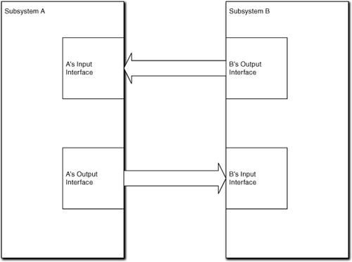
Generally, the Input Interface and Output Interface are defined once with the subsystem. They represent a single syntax for accessing the subsystem subject matter (input) or the external environment (output). They will move with the subsystem when it is ported to other contexts. Mechanically, whenever the objects that populate a subsystem need to send a message to the outside world, they talk to the subsystem’s Output Interface. That interface re-dispatches the message to the appropriate receiving subsystem’s Input Interface. (If you are familiar with design patterns, each interface is essentially a Facade pattern.) This completely decouples the implementations of any two communicating subsystems because all knowledge of the other subsystem is limited to the Output Interface implementation, and even that knowledge is limited to just the other subsystem’s Input Interface.
By postulating both an input and output interface for a subsystem, we have a very general way of getting around the problem of syntactic mismatch because the implementation of the Output Interface is regarded as part of the bridge implementation rather than the subsystem implementation. Thus the bridge itself can supply glue code to convert from one input interface syntax to another in the implementation of the Output Interface. Since client and service are agreed on the underlying semantics of the service, there must be a way to unambiguously convert between the syntaxes. That glue code depends only on the respective interface definitions; it is completely independent of either subsystem’s implementation. So, we can insert a service subsystem into a new reuse environment without touching its implementation by simply providing new Output Interface implementations for the relevant communicating subsystems.
This enables a subsystem to be completely portable without any change. It also enables any subsystem to be swapped with only minor changes to the bridge code, and those changes in no way depend upon the subsystem implementations. This also means that we can employ exactly the same bridge model for in-house and third-party subsystems; at most we just need to provide a wrapper for the third-party subsystems.
While converting one interface syntax to another should always be possible, it isn’t always easy. Just look at the contortions the interoperability protocols like CORBA or DCOM go through to pass object references across distributed boundaries. Fortunately, MBD makes this easier by limiting interface syntax to pure event-based, data-by-value messages. Though this was done to reduce coupling and make life easier for transformation engines, it also makes life much, much easier for providing bridge glue code.14
When client and service are developed together as part of the same project, it makes sense to negotiate interfaces that require minimal glue code. Such bridges are usually trivial 1:1 mappings, and even those can be optimized by the transformation engine. But there can be situations where the glue code requires an entire subsystem in its own right, though this usually only happens with third-party components.
Describing Subsystems
The partitioning of an application into subsystems is described in a Component diagram. For application partitioning there are only three relevant graphical elements: Subsystem, a classifier box with a predefined <<subsystem>> stereotype attached to the name; Dependency, a dashed line between client and service subsystem with an arrow pointing to the service; and Interface, which describes the subsystem responsibilities. Quite often we do not even include Interface elements because UML allows responsibilities to be enumerated in the Component classifier. They are primarily used to clarify when different clients define requirements for different service responsibilities.
The real documentation we need to provide about subsystems is typically attached to model elements as text tags. Because subsystems are so important, we need to describe them in some detail. This chapter subsection describes one fairly common approach to documenting subsystems. However, there are no standard rules for such documentation; use whatever works to ensure proper communication in your shop.
Subsystem Descriptions
Usually a paragraph or two is sufficient. The goal isn’t to document the solution, only the containers for various parts of that solution. The objective here is simply communication—to just record as precisely as possible what the team thought each subsystem was relative to the customer problem in hand.
There are no hard and fast guidelines for what the description should address. But the following tidbits are often useful.
Is, not How. The basic idea here is that the primary goal is to describe what the subsystem is rather than how it does something. This perspective should dominate the description. Name subsystems with nouns, and then think of the description as a definition for that noun.
Responsibilities. It is often useful to clarify what sorts of responsibilities the subsystem has. At this point we should not yet know exactly what each subsystem will do, but we should have a pretty clear idea of what kinds of things it should know about and do. The notion of responsibility provides a more generic view than itemizing tasks or data.
Level of abstraction. This is an indication of the level of detail at which the subsystem will be implemented. Sometimes this is done by example, as in, “This subsystem deals with pin states only as an aggregate. It would not process individual pins.” This is especially important when a large subject matter is split into an overall control subsystem and one or more subsystems that provide narrowly defined, detailed services. That division needs to be carefully defined.
Services. Sometimes it is convenient to describe a subject matter in terms of the services that it provides. This is somewhat different than describing responsibilities because the emphasis is on the client/service relationship. It is useful when subsets of responsibiltiies are closely related.
Invariants. It is often helpful to mention any relevant invariant that the subsystem represents. When the subsystem is implemented, this should help identify consistent class abstractions and processing metaphors. If the nature of the customer’s business already has standardized definitions, those can be referenced.
Mission. Some people find it convenient to think of subsystems in terms of missions. The important thing is to keep the description of the mission abstract so that you describe what the mission is rather than how it is executed.
Though this is an individual style issue, it may be useful to anthropomorphize the descriptions. This has already been done several times in this book. For example, when talking about GUI subsystems, phrases like “it only understands pixels, Windows, and Controls” were used. This is useful because it suggests a customer-focused view where the subsystem could be a job description for some manual process. In fact, thinking of a subsystem description as a job description is not a bad metaphor.
Relationship Descriptions
In theory there are two pieces to the description of a Component diagram relationship. The first deals with the client/service relationship between application partitions. The second deals with bridges that support communication between partitions. The former is concerned with requirements flows while the latter is concerned with interfaces and message flows. These are quite different things and MBD deals with them separately.
In fact, bridge descriptions are usually not part of the Component diagram relationship descriptions. This is because bridges tend to evolve during the development since the details of interfaces are often negotiated between teams working on different subsystems. Typically the bridge descriptions will be in a separate external document from the UML model.
Because the subsystem description will identify the individual services and responsibilities, it is usually sufficient to describe the relationship with a one or two sentence summary of the client/service relationship. That’s because we implicitly describe the sorts of requirements that the subsystem resolves in the description of the subsystem itself. Nonetheless, the relationship descriptions describe the nature of the dependency on the service so they are effectively a different “spin” on the requirements allocation. This is particularly useful when a service has multiple clients because the relationship descriptions can identify which particular services individual clients are expected to access.
It must be emphasized that we are talking about providing a general context for requirements rather than specific requirements. The intent here is to provide a guideline for when we must decide where original requirements and requirements changes should be implemented. In other words, good subsystem and relationship descriptions should make it fairly easy to allocate detailed requirements to specific subsystems later. Because this will also have to be done during long-term maintenance we want to keep the description stable, which means that we need avoid too much specific detail. Finally, the detailed subsystem requirements will be spelled out somewhere, like use cases, so we only need to identify who is driving those requirements and describe special situations.
Requirements Allocation
The actual allocation of requirements will typically be done by creating use cases for each subsystem. Because this is technically a systems engineering task, it is outside the scope of OOA/D so we won’t go into it here. The key idea, though, is that somebody needs to break down customer requirements to the subsystem level. Hopefully the notion of client/service relationships will facilitate that.
An Example: Pet Care Center
As a practical example, let’s consider some software to support a pet facility catering to upscale clients.15 The Center will have the usual accounting software (e.g., General Ledger, Payroll, etc.), but that stuff has been done to death in the literature, so let’s assume we are interested in software that tracks the processing of a pet through the Center. To avoid boredom we will skip the ten pages of detailed requirements from which we extract the high-level problem description. Instead, we will just provide a couple of paragraphs to describe the overall problem.
The main purpose of the application will be to collect data about what happens for billing purposes. This includes charges for things such as medications, food, length of stay, facilities required, special handling, disposal, and whatnot. The primary outputs of the system are online transactions to an external invoicing system and ad hoc reports on pet status. Each transaction itemizes (with time stamp) an individual cost accrued for an account associated with the specific pet. Costs for things like facility use are accrued on a daily basis. The primary inputs for the system are a database, user input when a pet is registered, and online input by the staff (e.g., procedures completed). The database provides medication doses and costs, diets, allocations for facility use, costs of procedures, an similar generic information. The database is unique to this software application.
The overall processing of a pet is in stages: admission, residency, preparation, treatment, and disposition. Some of these stages have multiple options. For example, disposition can be the owner’s responsibility16 or, in the event of the pet’s death, the processing may involve burial, cremation, memorial services, and/or organ donation. Each stage captures a suite of rules for determining things like medication and facilities required based on pet characteristics like size, species, and medical history—wherever possible barcode readers are used to facilitate progressing through the stages.
If you found the preceding paragraphs incomplete and imprecise, welcome to the wonderful world of commercial software development. Unfortunately, such flawed requirements are all too common. The goal from here on is just to provide an example of how we build a Component diagram and then document it. We begin with a summary of what might have been extracted from far more detailed requirements. The example exercise here is to laboriously “walk” through a mental process of identifying and documenting the subsystems and their relationships.17 So where do we start?
The top is usually a good idea. We have multiple stages with apparently different responsibilities. Some or all may end up as subsystems, but somebody has to understand the overall sequence of processing to coordinate them. To do this, we stick a Pet Tracker subsystem at the top of the diagram to handle the pet’s migration through those stages at a very generic level. Since we are in the early formative stages of defining the Component diagram, we don’t attempt to be more precise about what it is yet; we will revisit it as we get more insight from the services.
An experienced MBD developer would recognize some very frequently occurring subsystems immediately: persistence in the form of the database, user inputs, and hardware control (e.g., barcode readers). We have already talked about how persistence and user communications are low-level services that should be encapsulated to hide their specific mechanisms, so we tentatively place UI and DB Interface subsystems near the bottom of the diagram. Similarly, messages to/from other systems and hardware are also a low-level communication service whose mechanisms need to be encapsulated,18 so we put a Physical I/O subsystem with the others near the bottom of the diagram.
The requirements talk about things like “facility,” “cost,” and “memorial services,” but these seem more likely to be classes in a more generic subject matter or activities that take place outside the software. The only other entities the requirements talked about were the processing stages. We can make a reasonable case that each stage is a different subject matter with different responsibilities. But do we need to do so? In this case, maybe we don’t because some of the subject matters will be almost trivial.19
For example, what is Admission really about? Most likely it is filling out one form with pet information and getting an account number to associate with it. The form itself will be handled in the UI subsystem, so all we have is a data holder class and some simple message exchanges with the database and whoever assigns account numbers. Residency is also fairly simple in that it really just determines the stall, cage, or whatever the pet resides in and what to feed it.
Whoa. Feed it? Why decide that in Residency rather than Admission? Let’s look at this more closely. Actually, there seems to be two distinct responsibilities here: decide the diet and actually provide food to the pet over time. The first seems like something admission processing would do because it is related to the type of pet, which is first determined in Admission. In addition, the pet owner may wish to specify a special diet, or particular treatments may require a special diet. (The diet itself can reside in the database; all we need is to associate the diet identifier with it during registration or treatment.) Similarly, the diet may change during treatment. OK, make a note of that for the documentation. The actual diet will be in the DB, and the various stages will simply associate the diet identity with the particular pet.
The second responsibility seems like part of the residency because the notion of being resident is open-ended in time. Therefore, the residency just needs to be notified when it is time for feeding. It can get the diet from the DB.
But scheduling meals triggers another thought: There may be several things scheduled. When the pet transitions from stage to stage will have to be scheduled. If the pet dies and must be cremated, this likely will have to be scheduled based on resource availability. Medications during Admission & Residency may have to be scheduled. Having lots of stuff to schedule should suggest making scheduling a central notion of the solution. Should schedules be generated automatically, or will they be input by the user?
The requirements statement didn’t say, so we need to talk to the customer again. However, we can be pretty sure there will be a Scheduler subsystem even if we don’t know yet exactly what is being scheduled. That’s because even if the user inputs the schedule, somebody will have to store it in the database, generate events for its activities, and retrieve/display it. For instance, whoever prepares and/or delivers the food needs to know what to do and when. But since manual scheduling is a pain, the customer is odds-on to opt for automated scheduling either now or as a later enhancement. So tuck a Scheduler subsystem on the diagram in the lower half, but above the UI, DB, and Physical I/O subsystems, because it may use them as services.
Back to whether each stage is a subsystem. As long as scheduling is handled elsewhere, the Admission & Residency stages still don’t seem terribly complicated; they just exchange some messages with other subsystems and provide user data entry. In particular, Residency really doesn’t do anything except look up some data and compute a cost value when it receives a message that some event occurred (e.g., a meal was served or a day passed). It is hard to imagine these subject matters requiring more than a handful of classes in combination. In fact, we can almost envision a Pet class whose states were something like Admitted, Housed, Fed, and so forth. However, that would be getting ahead of the story by describing how the responsibilities were carried out. So slap yourself upside the head, Grasshopper, for even thinking that. Just put an Admission & Residency subsystem just below Pet Tracker.
OK, what about preparation? What’s involved? We move the pet from its temporary abode to the Treatment facility, possibly tranquilizing it first if the treatment involves surgery or the pet has a nasty disposition. Again, that is not a complicated scenario; we might just slip something into the pet’s last meal. It is difficult to imagine any need for a separate subsystem to encapsulate that subject matter. Since the preparation may be initiating the Treatment itself, we can safely combine the preparation stage with the treatment stage. To do this, we put a Treatment subsystem on the Component diagram next to Admission & Residency.
The pet gets treated in some kind of facility. In fact, there may be several facilities for radiology, operations, electroshock, and whatnot. Are these subsystems? Probably not in this application. Most of the actual activities in the Pet Care Center will be carried out by real people. The only thing relevant to this application is scheduling them and charging for them. At that level we just need to know the type of activity.
This is worth a bit more thought, though. Basically, the application records a bunch of pet and charge data, all of which it gets from real people through the UI. To schedule activities, it just notifies a real person that it is time to do something and that person eventually tells the software when it is done—again, all through the UI. In many respects this application is very much like the ATM controller; it is effectively just sending and receiving messages that happen to be related to scheduled activities. So far the only interesting functionality it seems to have is scheduling things.
If that is the case, do we really need subsystems like Treatment or Admission & Residency? We may not. But let’s keep them as candidates for a bit because they may need to enforce business rules and policies. For example, we can readily imagine an admissions process that required things like credit checks, insurance processing, and whatnot. That level of business complexity might well warrant subsystem encapsulation. If they turn out to just be pass-throughs for decisions made in the core accounting systems, we can get rid of them later.
Another reason for keeping Treatment is that it may involve special hardware usage (e.g., X-ray, MRI, etc.). There may also be things like repeated treatments and diagnostic processes. Treatment may be quite different depending on the pet and problem. This sounds like more complicated business rules and policies that we might want to isolate and encapsulate.
So let’s look at the Disposition stage. The pet may have to undergo an extensive period of rehabilitation with its own scheduled physical therapy sessions, special diets, and so forth. Even if there is no rehab, the pet may need to stay someplace until the owner comes to pick it up. Things get complicated if the Pet Care Center can’t save the pet and it expires. It may then need to be buried or cremated, and there may be a need to provide a funeral service. This implies the pet may have to be stored someplace temporarily.
In fact, the entire disposition of the pet in the event it dies seems potentially complicated with a need for special scheduling and coordination. Storage is similar to preparation in that there really isn’t much to it. Moreover, if the elected disposal mechanism is immediately available, no temporary storage would be required. If we reason that storage is also a form of disposition, it is easy to combine it with the Disposition subject matter.
But the other activities involved in actual disposal of the pet remains seem like a different subject matter. We might want to tentatively break those out from Disposition as a separate service, like Remains Disposal. The requirements indicated more complexity for Remains Disposal than any of the other subject matters. We can easily imagine fairly complicated scenarios combining everything from obtaining burial permits to reserving a cathedral.
Whoops. Burial permits? Reserving cathedrals? Wouldn’t they be done before the actual disposal (e.g., while the pet was in storage)? No doubt. But the software doesn’t actually do those things; it prompts the staff to do so. It is more likely the prompting would be done by Scheduler. That prompting will be scripted in a fixed sequence based on a strategy for disposal. Presumably the staff will select a particular strategy (e.g., cremation without services) based on the owner’s wishes. Make a note of that.
Let’s get back to Remains Disposal’s responsibilities. They are certainly more complicated than the other stages, but it is clear they are not so complex that it warrants breaking up Remains Disposal into specialized services like Cremation. Remember, this application is about tracking costs as a pet passes through the Center’s processes. Disposal will be notified of events that incur cost by the user or the hardware. All it really needs to do is compute the cost associated with the event. There may be several rules for this, but it isn’t going to require fifty classes to encapsulate them. Make a note of that too.
While we are at it, let’s think about levels of abstraction. Who coordinates activities like wakes, funerals, and cremations? If we let that be done in Remains Disposal, there isn’t a whole lot left for Disposition to do except notify the pet owner and manage temporary storage of the remains. Alternatively, we could think of Disposition as providing high-level control and coordination of the pet’s disposition in all scenarios. Since that high-level control would apply to disposition of a cured pet as well, that intuitively seems reasonable. In effect, Disposition makes decisions about what needs to be done and manages its sequencing at a high-level of abstraction. It then turns over control to Remains Disposal for the details.
As a sanity check, let’s look at what Remains Disposal’s mission is if we move the high-level coordination out of it. We have already decided that the Scheduler subsystem is going to handle all things related to scheduling. Presumably, Disposition will tell Scheduler what events to schedule and the sequence. (There aren’t very many combinations and each has fixed sequences, so Disposition probably only announces the combination and Scheduler manages the sequence.) But the activities are external and, given our conceptual view of the application processing messages, that doesn’t leave a lot for Remains Disposal to do except compute simple cost values.
Hmm. Maybe this isn’t as complicated as we thought, Grasshopper. What’s really involved? The application tells a real person to get a burial permit, schedule a service, schedule a burial, and so on. For each task the person tells the application when that is done. The application then sends a message to a real person when it is time to move the pet remains around for each of those activities. The real person confirms that the pet has been processed and the application accumulates the charges. This doesn’t sound like a bunch of complicated business rules and policies being applied to anything except the schedule, and much of that is likely to be “canned” for a handful of basic customer options.
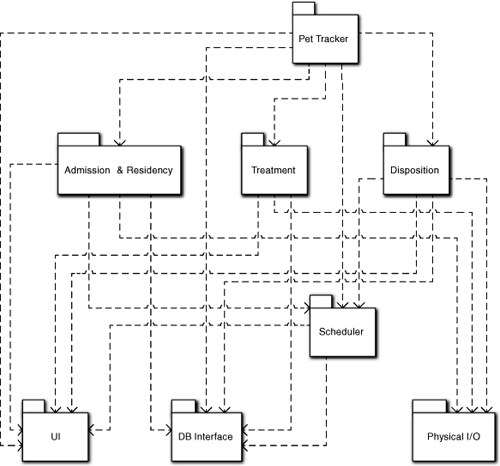
Basically, this is just a handshaking protocol between the application and the staff or the Scheduler subsystem. Since Disposition is already dealing with coordination of the activities, it seems like it could handle that protocol as part of the coordination it is already doing. So it seems pretty safe to drop Remains Disposal as an important subject matter. Note that we can be pretty confident about this because we have already abstracted the fundamentals of what the application is doing in terms of sending and receiving messages (along with some scheduling responsibilities). The result of this preliminary partitioning are the subsystems in Figure 6-5.
Figure 6-5. Preliminary Subsystem Component diagram for a Pet Tracker application in a Pet Care Center
That is probably it for identifying the subsystems in an initial Component diagram. At this point, it would be a good idea to go through a checklist of the criteria from the previous chapters. We won’t do that in detail here, but we will point out how these subsystems capture the key ideas of cohesive problem space subject matter, level of abstraction, and client/service relationships.
Cohesive. The subsystems are readily identifiable as having different responsibilities. While we have combined some subject matters, the resulting subject matter is still distinct from other subject matters and readily identifiable by domain experts. In addition, the subject matters are narrowly focused. We had little difficulty in recognizing inconsistencies and allocating responsibilities.
Based on problem space. This is pretty clear for all but UI, DB Interface, and Physical I/O. For these three they are problem spaces, just different ones from the customer’s. One of the main reasons for encapsulating them was that they are unique paradigms distinct from the customer’s problem space (e.g., Window/Control, relational data model, hardware read/write, and network protocols). The other service subsystems were taken directly from entities in the requirements. Three were explicitly defined as stages. Scheduler isn’t explicit in the requirements, but it is doubtful that any domain expert is going to have a problem with it being an implicit need. Pet Tracker represents the purpose of the software in the problem space, but it is troublesome that it doesn’t seem to have a lot to do.
Level of abstraction. We defined Pet Tracker as providing the overall control at an abstract level. The three subsystems in the middle of the diagram are all at roughly the same level of abstraction because they represent stages of the same process. They are less abstract than Pet Tracker because they address individual processes. Scheduler clearly provides services for the subsystems above it. Since it is a quite orthogonal subject matter, it may not technically be at a lower level of abstraction, but it is certainly at a lower level of semantic detail that would apply outside the context of pets and pet care centers. The three subsystems at the bottom of the diagram are at a lower level of abstraction because they represent detailed models of implementation paradigms in the computing space that support software applications.
Client/service relationships. We haven’t talked about them yet, but implicitly we have identified them to some extent. We thought of UI, DB Interface, and Physical I/O as low-level services to the rest of the application. We described Pet Tracker as the coordinator of the stages in the process. The middle subsystems are those stages that Pet Tracker coordinates. Peripherally, we thought about the kinds of messages that these systems would exchange with external systems. To transmit those messages we need the low-level services of UI, DB Interface, and Physical I/O.
Before we can get a handle on the dependencies between these subsystems, we need to step back and get a grip on what the application is really about and what we expect to abstract in the subsystems. At this point it is often a good idea to take an initial pass at documenting the subsystems. This doesn’t have to be very formal—a few bullet items may do—and doesn’t require rigorous scrubbing. The purpose is to get everyone thinking along the same lines for what each subsystem is. The dependencies tend to fall out automatically as we define the subsystems.
We already noted that this application is about tracking a pet through a general process and associating costs with various activities in that process. It is worthwhile to think about how that tracking is done. A prerequisite for computing a line item cost is that some activity is completed, so the completion of an activity can be regarded as an event that triggers a cost computation. There are many mechanisms for announcing an event, such as the user completes an admission form and clicks a Submit button; an orderly swipes a barcode reader when a pet is fed; the system clock is polled to detect the end of a calendar day; and so on.
Various subsystems respond to those events. So far we have identified two sorts of responses. One will be nothing more than computing a cost and storing it in the DB. To compute the cost a subsystem needs relevant data, which is supplied either in the message data or is recovered from the database. Many of the triggering events will be generated by the staff through the UI as they announce completion of some activity like a treatment. Others will be generated by the Scheduler.
Hmmm. Storing a computed cost in the DB. How does it get to the Center’s core accounting systems? We could post directly to the core accounting systems as costs are computed. But there are practical reasons why that might not be a good idea here. Typically you don’t want to be posting tiny transactions individually to the enterprise DB when you could batch them. Also, immediate posting to an external system makes it more difficult to recover if somebody made a mistake (e.g., scanning the wrong barcode). Time doesn’t seem critical here, except having a bill ready when a pet leaves, so maybe batching up costs in the local DB is a good idea. But when do they go to the external systems, and who sends them? Sounds like another job for the Scheduler to trigger updating other systems periodically. And this gives the Pet Tracker subsystem something to do. But we digress. . . .
The second type of response is what the staff actually does, such as feeding the pets at the scheduled time. Since those are human activities, the software is not concerned with them. However, the software does have to tell the staff what to do when it is time to do it, since most of the staff are probably making minimum wage and not necessarily self-starters. Essentially these sorts of responses mean the subsystem needs to provide an appropriate notification to the staff through the UI. To do that, the subsystem will probably need to obtain other information from the DB, such as the diet for a particular pet, for that notification. The events that trigger these sorts of responses will very likely be generated by the Scheduler subsystem.
In fact, there is a pattern that becomes evident for all the stage subsystems.
- Receive an event from the Scheduler and decode it.
- Obtain data from the DB, if necessary.
- Send a message to the UI to notify the staff with any data from (2).
- Receive an event from the UI when the staff completes the task and decode it.
- Inform the Scheduler that the task is completed.
- Compute a cost and post it to the DB.
Perhaps more important, these activities are very linear (i.e., they don’t depend on other activities) and they only depend on the event identifier. So we have highly structured and very similar code for our activities. Moreover, at this point it has probably occurred to you that the subsystems representing the stages of the caregiving process don’t do a whole lot. We can readily envision some infrastructure, such as lookup tables and whatnot, but essentially each event has a well-defined set of simple behaviors that are triggered by the event identifier.
The real intelligence in this processing lies in Scheduler as it decides when to generate particular events. In effect, we have defined all the important sequencing of activities in the application solution in terms of schedules. But even Scheduler isn’t that complicated. It generates an event in one of two situations: to announce the next thing to do (e.g., move the pet to rehab) when it receives an event announcing completion of some activity (e.g., a treatment procedure is done); and to announce that the right elapsed time has passed in the schedule (e.g., it is feeding time).
Uh, oh. Where does Scheduler get stuff like the stage sequencing or feeding schedules? To answer that we need to look at what sorts of information it needs to do its job. Basically it needs the following sorts of “schedule” definitions.
Fixed periodic schedules. These are needed for things like feeding cycles and rehab time. Somebody has to tell Scheduler what the events are and the elapsed time between them. Does Scheduler need to know about what to feed the pets? No, that’s a job for someone else, like the individual stages that respond with the right activity for Pet type. (In practice we will probably store diets in the DB for classes of pets and treatments.)
Stage transitions. Essentially the stage sequencing needs to be “hard-wired” into Scheduler. That’s acceptable because it is an invariant to the way the Pet Care Center is run. (In practice that is likely to be trivial—just a lookup table that maps announcement events, based on event identifier, into the events to generate for the transition.) If we are clever about this when implementing the Scheduler, we can describe almost any “hard” sequence in the problem space this way as long as other subsystems tell Scheduler when they are done with individual activities. Note that we can map things like complex disposal sequences into stage transitions in the same way; the scale and scope are just smaller.
OK, so who provides this information? That’s partially a design issue. For example, recall the discussion of invariants and parametric polymorphism in Chapter 5. The stage transitions are just a mapping among event identifiers from Scheduler’s perspective. Since event and stage identifiers are just data, the mapping can be defined in external configuration data. Then sequencing is not even “hard-wired” in Scheduler; it is “hard-wired” in the configuration data, which can be changed without touching the application.
While stage transitions are likely to be invariant over the life of the application, other sequences might be somewhat more volatile. Therefore, we would probably like a user-friendly tool to modify the configuration data. That is a data entry problem much like entering pet information during registration, so it shouldn’t be difficult to handle it the same way. But because that is much broader than individual pet admission, we would probably let Pet Tracker manage that sort of system-level data entry.20
What about periodic schedules? Superficially, those seem to be dependent on individual pets. But are they really? A pet’s diet is likely to depend on the type of pet; if people don’t get a lot of choice about meals in a hospital, why would pets be any different? It could also depend upon the type of treatment. Either way, though, the diet is likely to be predefined prior to the pet entering the Pet Care Center based on combinations of pet type and treatment. That’s a job for the database; define the combinations once. Obviously, the same thing applies to the feeding schedule.
Again, all we need is a data entry facility for entering diet and schedule based on pet types and treatments. Managing that in a user-friendly way would also be a Pet Tracker responsibility. If this is an upscale Pet Care Center we might support special dietary rules for individual pets, in which case that data entry would be part of the admissions data. Obviously these same observations apply for any periodic schedule.
We can now take a stab at the dependencies on the low-level subsystems. This is summarized in Table 6-1.
Table 6-1. Dependencies for Pet Care Center
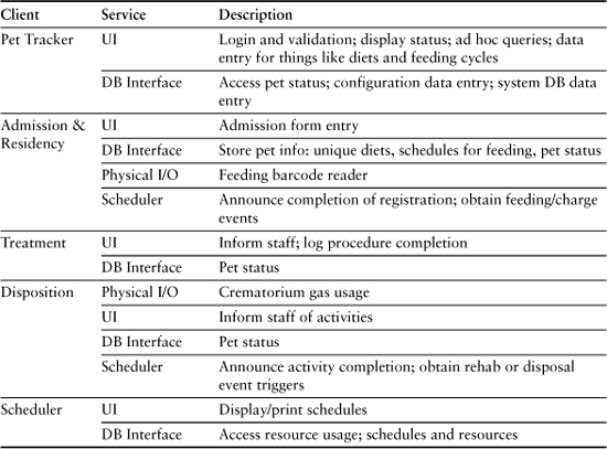
As a practical matter, all the subsystems except UI will probably be clients of Physical I/O for barcode reading. The phrase “pet status” is a catch-all for any pertinent information about the pet, including charges made.
Note that our view of subsystem responsibilities has been significantly refined, especially since thinking about the sorts of events and responses we have, and the role of Scheduler in the overall solution. This has led to a rather simple event-based model of how things work, where the notion of a “schedule” drives almost all of the large-scale processing. This in turn has allowed us to anticipate parametric polymorphism in the solution so that the “schedules” are defined in terms of data and are stored externally.
If you try to envision the code needed to implement the subsystems, you will probably conclude that it will be a lot simpler overall than you originally anticipated. Basically it will be an exercise in accessing lookup tables.21 The use of invariants and parametric polymorphism is the immediate cause of that. However, they are enabled by the insights we had around Scheduler, the notion of schedule, and the use of events to announce that the state of the solution has changed. Perhaps most important of all, our abstract view of the way things work and how that maps into announcements of activities done by the staff interacting with the notion of schedule has greatly simplified our big picture view of what is happening.
The dependencies in Table 6-1 yielded the Component diagram in Figure 6-5. Coming up with such models is easy for experienced modelers but not necessarily so for novices. So it is worth spending a bit of time describing how the model elements can be traced back directly to First Principles of OOA/D in general and MBD in particular.
Regardless of the level of abstraction, all communications are in terms of announcements. One subsystem announces some new condition in its processing. Another subsystem responds to that announcement by doing something.
First notice that we sneaked in the notion of events even though there wasn’t a state machine in sight yet. That’s because events are pure announcement messages that have no expectation of a particular response. As discussed previously on several occasions, that communication model effectively eliminates implementation dependencies. But it goes a lot further than that in this design.
To analyze the dependencies, we needed to think about communications at an abstract level. Using the asynchronous event model enabled us to think about sequences of activities in terms of connecting conditions that prevail in the application solution as it executes. That was crucial to the Scheduler perspective of, “Tell me what you did and I will let someone who cares know what to do next,” enabling us to isolate all of the invariant, systemic sequencing in Scheduler for stage transitions. That is, Scheduler knows who cares about the condition, rather than the subsystem that raised the condition, because that is a different set of business rules.
It was only a short step from there to realize that the same basic mechanism can be used for more volatile sequences than stage transitions. In turn, that leads to the idea that we can use the schedule metaphor for the mechanism (i.e., the stage transition sequence can be represented as a schedule). This leap of faith is greatly facilitated, in turn, by the fact that we already identified a Scheduler concept in the problem space and have done some thinking about what the notion of schedule actually meant.
Of course, it didn’t hurt that we had already thought about what the notion of activity meant and had already expressed it in terms of a sequence of generic steps. Bracketing those activities between a trigger event and an I’m Done announcement event becomes natural once we are preconditioned to thinking in terms of event-driven processing. That, in turn, provides a pretty easy mapping into the daisy-chaining implicit in the schedule metaphor. Ain’t it great when a plan comes together?
Now let’s look at the sorts of descriptions we might provide for the Pet Care Center. The intent here is to demonstrate the kinds of things we need to describe. The specific descriptions will differ depending on the actual requirements, and the view is biased by the author’s personal preconceptions about what those might be.
Pet Tracker
This subsystem provides overall control and coordination of the progress of pets through their processing at the Pet Care Center. The primary mission is three-fold. Pet Tracker provides an entry point into the application when pets are admitted to the Center. Pet Tracker provides an entry point into the application for ad hoc queries on pet status for staff and other interested application users. Finally, Pet Tracker provides high-level facilities for data entry for configuration data and systemic database information that is independent of particular pets.
Pet Tracker collects cost transactions from the database on a periodic basis (or when a pet leaves the Center) and forwards them to the Center core accounting systems. Pet Tracker also provides ad hoc reports on past and current resident pets.22
Scheduler
This subsystem is the core of the application because all activity sequences are viewed in terms of a schedule metaphor. It has responsibility for generating schedules for individual pets based upon data in the database and information gleaned during pet admission. In creating schedules it provides resource leveling to avoid bottlenecks. It also has responsibility for updating affected schedules for resource utilization when a scheduling conflict arises (e.g., due to a pet going over its schedule when using limited resources).
The Scheduler also monitors the schedules of pets currently being processed and generates events to notify clients about scheduled activities. In doing so, it can incorporate lead times predefined in the database for certain activities to enable staff members time for preparations. The Scheduler manages timers to detect when activities are overdue.
The Scheduler provides events for specific sequences of activities, such as transitioning between processing stages. This is essentially a re-dispatch of activity completion events to the subsystem that needs to respond based upon the Center’s rules and policies, which are defined in external configuration data.
The Scheduler provides an interface to support predefined queries on individual pet schedules and reporting on pet schedules.
Admission & Residency
This subsystem handles the responsibilities for admitting a pet to the Center and processing it as it awaits treatment and during rehab. Admission is contingent on whether suitable accommodations and other facilities for the pet are available. To admit a pet, the subsystem accepts data on the pet from the UI. It then invokes the services of Scheduler to create a schedule for the pet. That is sent to the UI and, if approved, the Scheduler is notified to store the schedule, and the pet data is also stored.
The responsibilities associated with pet residency are basically assigning an available location for the pet based upon pet characteristics (size, disposition, etc.) and ensuring the pet is fed. The parameters for this assignment are pet data and configuration information in the database. Thereafter the subsystem responds to events from the Scheduler that announce necessary periodic processing, such as feeding and grooming. The subsystem then employs the UI subsystem to provide instructions for the staff. When the staff completes the tasks the subsystem is notified through the UI and barcode reader, and costs are computed. If a task is not performed within a predefined delay for the pet, an appropriate alarm message is sent to the UI to notify the staff.
This subsystem generates transactions to the database as costs are incurred for room and board. The charges are based on data for the pet and its type stored in the database.
Treatment
This subsystem handles the preparation and treatment of a pet. Based on data from the database, an event is sent to the UI containing any staff instructions for the preparation and treatment of the pet. The instructions are predefined based upon pet type/illness and are accessed from the database. The subsystem issues the instructions to the staff through the UI when a pet transitions into or out of the stage.
The staff informs the subsystem, who informs Scheduler, about any changes in the availability of specialized resources within the stage. Charges are accrued when treatment is completed.
All treatments are viewed as one or more individual medical procedures (x-ray, colonoscopy, mastectomy, etc.). When multiple procedures are required, the subsystem coordinates the sequence with the Scheduler.
Disposition
This subsystem is responsible for post-treatment care (rest, rehabilitation, etc.) until the pet is released from the Center. This subsystem is also responsible for processing a deceased pet. That processing may include storage, cremation, burial, and funeral services. The subsystem provides messages in the UI to Center staff members to initiate various activities in the disposition. These messages are triggered by events from the Scheduler subsystem.
The subsystem is responsible for knowing what pets are currently in the stage and their status.
Periodic charges for storage are accrued based on periodic events from the Scheduler. Charges for crematorium fuel are based on events from the Physical I/O subsystem that indicate the fuel consumption. Charges for disposal processing are accrued when the staff indicates that disposal is completed. All charges are computed from parametric data associated with pet type in the database.
Physical I/O
This subsystem provides an interface to the crematorium hardware. It identifies when the hardware is turned on and off. It also monitors fuel flow rate from sensors. The subsystem notifies Disposition when the system is turned on and off. When the cremation is completed it notifies Disposition of the average fuel flow rate.
The subsystem also manages data retrieval from various barcode readers in the Center that identify particular pets. The subsystem dispatches an event to the appropriate subsystem for the barcode reader identity.
Database
This subsystem provides an interface to an RDB database. The database contains data about pets, their schedules, various parameters based on pet type (medication, facilities required, and the like), and current charges. The data is highly specialized to the application. The database also contains configuration information (e.g., stage transitions) and systemic information (diets based on pet type/treatment, disposal options, etc.).
This database is separate from the Pet Care Center’s core accounting systems. The only synchronization is periodic posting of costs to the core accounting systems.
UI
This subsystem provides communications between the other subsystems and the end user (usually a staff member). It must handle a variety of communication paradigms for form-driven data entry, ad hoc queries, predefined reports, and special notifications. The UI will be GUI-based on terminals at various locations in the Pet Care Center.
Caveat. The example should not be taken literally because we were very sloppy about requirements due to space limitations, and everyone will have some preconceived notions about what they may have been. So it is quite possible other designs would work well for different preconceived notions. The important points of this example are (a) to demonstrate the level of documentation one needs, and (b) the thought processes, particularly abstracting essential elements of the processing and developing design metaphors used to arrive at this design.
Processes
Generally, it is a good idea to have your customer(s) present during the initial cut at identifying subsystems. The customers don’t have to know any fancy notation, and you are talking about their problem space so there is no learning curve for them. Make sure the whole team is there and emphasize that they should listen carefully to whatever the customers say. One of the many possible processes is
- Blitz. This is a basic technique whereby everyone blurts out candidate names for subsystems. Each is accompanied by a sentence or two describing it. No suggestions are rejected at this time, even if the person suggesting it wants to recant. No candidate is criticized. The only goal is to provide a stream-of-consciousness list of possible subsystems. Each candidate’s name and description are written on a yellow sticky note and placed on a white board for later consideration. People will usually run out of bright ideas within about five minutes.
- Preliminary scrub. Each candidate is considered one at a time and scrubbed in a cursory fashion for a 1- to 2-sentence description that everyone can agree with. The idea is to eliminate those that are obviously not going to be subsystems. The most common reason for rejection is that it is too detailed (i.e., it is more likely to be an object within a subsystem). Another common reason is that another candidate conveys the intent better. Whatever the reasons, rejection requires two conditions: everyone agrees, and the decision is obvious. Don’t spend a lot of time on this; it is just a preliminary screening.
- Organize. This is a group effort where everyone mills around the white board and arranges the yellow sticky notes with the candidate names. High-level candidates are placed toward the top and service candidates that support higher-level candidates are placed toward the bottom. Candidates that people feel may be the same or very similar are placed adjacent to each other. Don’t worry about specific dependencies. There may be some disagreement. Let people articulate why they feel their way is best and seek consensus. When in doubt, the customer’s view should always carry the day. Though this is the first real opportunity to clarify the overall semantics, don’t let it go more than half an hour or so.
- Eliminate duplication. You now have a vague hierarchy of level of abstraction, some notion of service relationships, and have talked about at least some of the subsystems in more detail. Turn the discussion to eliminating candidates that can be included in other candidates. Focus on semantics that seems to have a high degree of overlap. If successful, combine the yellow sticky notes with the final subsystem on top. Don’t overdo it; just merge the obvious candidates where there is consensus. When in doubt, don’t merge. When there is disagreement let people talk it out, but don’t let this go beyond fifteen minutes or so.
- Semantic analysis. This is the crucial step where the customer’s view is the most important. Ask the customers what they think each candidate subsystem is about. The developers should push back for clarification. In the end, everyone should be clear about the issues and questions earlier in this chapter—those issues and questions should act as a mental checklist against the description. If other candidates were coalesced into the subsystem, check that their semantics has been properly incorporated. The discussion may remove candidates, merge candidates, or even add new subsystems. The customer is the driver here, and the developers would be well advised to take notes because the subsystem descriptions need to line up with the customer’s view.
- Client/service relationships. Here we identify the responsibilities of the subsystems and what sorts of services they provide. Use a dry marker to identify the relationships. Here the developers are likely to drive because they probably are more used to the notion of delegation. The goal is to allocate requirements in a broad-brush manner and get the level of abstraction right. The process is iterative with the previous step in the sense that allocating responsibilities also refines the semantic definition.
- Model. The developers go away and build a Component diagram to designate the subsystems. Have someone with a good memory write up the subsystem and relationship descriptions as tags in the model. (It is usually a good idea to designate this person before the blitz so that they can take notes on discussions to refresh their memory later.) Subsystem descriptions are usually a couple of paragraphs; dependency descriptions are usually a couple of sentences.
- Review. Review the model and descriptions with the team and customer. This is the final scrubbing and usually requires a dedicated but highly focused meeting. At this point, you want consensus at a rather pedantic level because you are dealing with natural language descriptions, so be prepared for some debates.
- Allocate detailed requirements and define bridges. These are really separate activities from defining the Component diagram. For large applications, allocating the requirements can be a systems engineering task. Requirements are allocated as soon as the Component diagram is available, but defining bridges can be deferred because that will often be a matter of negotiation between the teams implementing participating subsystems in an original development.
There are lots of variations on this process. Choose whatever seems to work best in your development culture. Just remember that the key goals are consensus and communication.
Legacy Replacement: A Practical Example
There is an interesting process that is worth mentioning here because it provides a concrete example of the power of disciplined application partitioning. Software shops are almost always saddled with vast quantities of legacy code. Quite often it is poorly documented, difficult to maintain, and employs obsolete technologies so there is a strong desire to replace it.
There are basically three strategies for replacing legacy code:
Rewrite the entire application. Essentially, we create a brand new application and replace the old application with it once it is done. This is fine for small applications but is rarely feasible for larger applications because the entire development staff can’t disappear for a few years to create the new application.
Purchase a replacement. This is just a trade-off between development effort and money. In practice, though, this can also be a major headache because the new system must be properly specified and managed for outsourcing. For OTS purchase we need substantial evaluation, and we may be seriously screwed if it doesn’t work for all local contexts.
Piecemeal replacement. Here we replace modules individually in the old system over time in a prioritized manner. Traditionally, this has been a disaster. One problem is that it is very difficult to estimate the effort in excising old code to replace it with new code, so there is high schedule risk. The main problem, though, is that the standard techniques for identifying modules to replace are either on existing modules’ boundaries or based on minimum cut set.23 Either way, we are building the new application based upon the structure of the old application. But the most likely reason for needing to replace the old application is that it was unmaintainable because of lousy structure. So we just repeat the sins of the past and end up with a new system that is just as bad as the old.
The approach described next assumes piecemeal replacement, but it employs a rather novel way of identifying modules to replace. Instead of identifying modules in the old system somehow, we identify the subsystems we would want to have in the new application. We then apply the notion of two-way interfaces to drive the way we actually deal with the legacy application. Thus the Bridge model just described enables a technique to systematically isolate the new module in the legacy application that breaks up the development into phases that are much more manageable.
There are seven phases, or steps, in this approach:
- Partition the ideal new application. This is essentially the first phase of an original development using the techniques of this chapter. This focuses on the application structure we want at the end of the replacement.
- Select a subsystem and develop it using the same requirements as the legacy application. Again, this is standard initial development, including providing use cases for the subsystem. Fully test the subsystem, which you can do because of the nature of the interfaces.
- Define an interface for the subsystem from (2) using the Bridge model. This would be the ideal interface we would use in the new application.
- Identify the legacy code that resolves the same requirements as the new subsystem from (2). This is a routine, albeit tedious, job for reverse engineering tools and code inspections.
- Insert the interface from (3) into the legacy code to isolate the code in (4) from the rest of the legacy application. This is the step with the highest risk, and it will be the trickiest because the legacy code will probably not be structured in a convenient manner. Consequently, we will probably have to perform some surgery on the legacy code just to access the interface. Use the implementation of the output interface to talk to the legacy code outside the code being replaced. The input interface implementation will be the one originally used to test the new subsystem in step (2). Note that the working legacy code that actually resolves the requirements remains in place.
- Run the regression test suite on the legacy application with the interface in place. Since the code actually resolving the requirements (i.e., the code inside the interface) is the original legacy code, we are only testing whether it has been properly isolated. Because step (5) is difficult, there will be problems, but they will be well focused on the interface.
- Once the interface works properly, excise the relevant legacy code from (4) and plug in the new subsystem. The implementation of the input interface is modified to talk to the new subsystem. Since that subsystem has already been fully tested in (2) and uses the interface already in place from step (5), this should Just Work. But you probably want to run the regression suite anyway.
- If there are unimplemented subsystems remaining, go back to step (2).
There are several unique things about this approach. When we are done, we have exactly the new application that we want because each subsystem was created exactly as it would have been in an original development. This ensures that we do not repeat the mistakes of the past. Except for steps (4) and (5), this is normal development that the shop should be able to undertake without any special risk.
Steps (4) and (5) make the project much more manageable because they separate the concerns of isolating the replaced code from developing it. Though step (4) is nontrivial, tools from reverse engineering are especially suited to that task. The hardest part will be ensuring we have correct requirements, but we need those for step (2) anyway. We just have to find where those requirements are resolved in the legacy code.
Most of the project unpredictability and risk will be connected with the surgery on the legacy code needed to insert the new interface to isolate the code to be replaced. But inserting the new interface between the code to be replaced and the rest of the legacy application is a very narrowly defined task, and it is greatly facilitated by using a two-way interface so that glue code for syntactic mismatches can be isolated easily. The only big problem will be converting the surrounding legacy code to invoke the new interface. While tedious and error prone, it is deterministic because the resolution of requirements on each side is the same, so the underlying semantics of the functionality accessed must be the same.
Steps (4) and (5) are also “front loaded” in the sense that they get easier as the overall project progresses. That’s because as more subsystems are replaced there will be more interactions with the interfaces of previously replaced subsystems. This means less surgery on the legacy code given that the previously replaced subsystems already provide exactly the interface we need. So, as we approach the end of the project the development effort and risk should approach that of the shop’s normal original development.
The real key, though, is that steps (4) and (5) are manageable because their scope is very narrowly defined, making them easier to estimate, plan, and execute. It also makes risk much easier to evaluate when rummaging through the legacy code. But all that is only possible if a disciplined approach to application partitioning, “firewall” interfaces, and the Bridge model are used.
This approach is also versatile from a project management viewpoint. If the shop decides to replace more than one subsystem at a time, that can be done by largely independent teams since the only opportunities for toe-stepping are in steps (4) and (5). (The elapsed time for steps (6) through (8) is probably measured in hours.) The bulk of the work for each team should be in steps (2) and (3), so synchronization problems can be minimized.
What about requirements that change during the piecemeal replacement? The only situation that matters is when a change applies to both the legacy code and the subsystem currently under development, and customers can’t wait until the new subsystem is in place. Then both the old and new code will have to be modified. But, assuming there is a reasonable change management process already in place, that just becomes a communication problem for the requirements.