14
Priority Arbiters
14.1 INTRODUCTION
In this chapter we present arbiters, originally presented in [87], which use priorities to generate grants. Traditional applications of arbiters with simple priority disciplines such as linear priorities and a priority ring are well known. Here, a more advanced formulation of a priority discipline is given, which is understood as grant calculation based on the current state of the request vector.
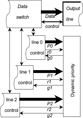
As an example of a practical application for such priority arbitration we recommend the reader to consider a fast network priority switch, shown in Figure 14.1. It has three input channels requesting access to a single output port. Every request is accompanied with a priority value transmitted through a dedicated priority bus. Priority values (attributes of requests) are generated dynamically. A dynamic priority arbiter takes a ‘snapshot’ of the request bus and calculates grant as a function of the request states (active or inactive) and the state of those priority busses which are accompanied with an active request. The priority discipline of an arbiter is formulated as a combinational function defined on the current state of request inputs, which is less restrictive than conventional, ‘topological’, mappings, such as that used in a daisy-chain arbiter.
Figure 14.1 Network priority switch. Reproduced from Figure 1, “Priority Arbiters”, by A Bystrov, D.J. Kinniment, and A. Yakovlev which appeared in ASYNC'00, pp. 128–137. IEEE CS Press, April 2000 © 2002 IEEE.
14.2 PRIORITY DISCIPLINE
All arbiters exhibit nondeterministic behaviour. The purpose of any asynchronous arbiter is to convert a stream of concurrent requests into a sequence of grants. Concurrency implies causal independence, which means that events on any two request inputs may occur in one order, in the opposite order or simultaneously. If two requests arrive with a significant separation in time while the arbiter is not busy with processing any other requests, then it is indeed impossible to reverse the order of grants by assigning different priorities to them. This creates confusion in understanding the concept of priority, which just does not work in the described scenario. All arbiters, with or without priority mechanisms, will behave similarly in this case.
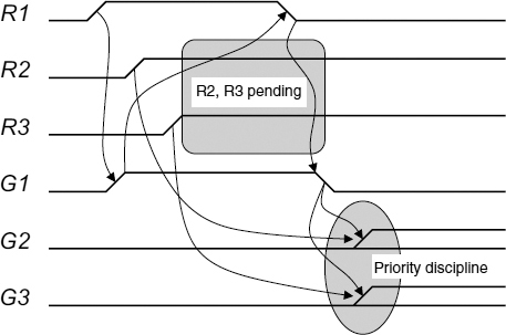
However, arbiters differ in handling pending requests. Complex multi-way arbiters usually perform arbitration of pending requests concurrently with the execution of the critical section in the process which is currently granted. The arbitration results are stored in the internal memory and are used to compute a grant after the currently processed request is reset. Grant computation is illustrated in Figure 14.2. At first the three-way arbiter is idle, no requests R1 … R3 are present and all grant outputs G1 … G3 are in the passive state. Then the first request R1+ arrives. The first grant G1+ is generated immediately after R1+. There is no decision-making involved as R2 and R3 are still passive. Then two other requests arrive while G1 is still high. Propagation of these requests is blocked by G1, the effect known as request pending. Only after the first channel has finished and G1 switched to low, the other grants can be issued. The requests R2 and R3 are ‘equal’ at this stage, as both of them are active. The choice of which request propagates first can be either random or based on a rule of choice, otherwise known as a priority discipline.
Figure 14.2 Priority discipline.
The method of grant computation can be used for classification of complex arbiters. If such a computation takes into account the history of request processing (service history), then the arbiter is said to exhibit sequential behaviour or sequential priority discipline. Token ring, mesh and tree arbiters fall in this class. If the computation is entirely based on the current state of the request vector, then the arbiter has a combinational priority discipline. Such arbiters are referred to as priority arbiters (PA).
The following dimensions of the priority discipline taxonomy can be identified:
- memory (combinational–sequential behaviour);
- primary data (void–scalar requests–vector requests–request order);
- implementation (direct mapping–logic function).
These dimensions can be combined to describe a particular arbiter. For example, the tri-flop MUTEX, as in Figure 3.18, generates outputs according to the gate thresholds if two requests are pending. As no information is provided with the inputs for the conflict resolution, then the primary data type is ‘void’. Its priority function is combinational and the implementation of the priority function does not belong to the logic domain (thresholds are analog values), which is typical for simple arbiters. Another example: the busy ring arbiter in Figure 13.8 belongs to the sequential type, its primary data is of scalar type and the priority discipline is implemented by the direct mapping of the model into the ring circuit structure. In the following sections we will describe several arbiters, which illustrate the above taxonomy.
14.3 DAISY-CHAIN ARBITER
The direct mapping implementation type of the priority discipline taxonomy is illustrated in the example of a daisy-chain arbiter with linear priorities (combinational priority function) and scalar requests.
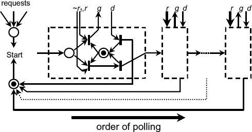
The two-phase STG in Figure 14.3 shows that the priorities are defined by the order of request polling. Each stage either has a request outstanding at the time of polling if r is true, or not, if ~r is true. The order of polling, and hence the priority of each request cannot be changed without changing the topological structure of the system.
Figure 14.3 Daisy-chain arbiter model. Reproduced from Figure 2, “Priority Arbiters”, by A Bystrov, D.J. Kinniment, and A. Yakovlev which appeared in ASYNC'00, pp. 128–137. IEEE CS Press, April 2000 © 2002 IEEE.
14.4 ORDERED ARBITER
The following design is an example of implementation of the request order type of the priority discipline taxonomy.
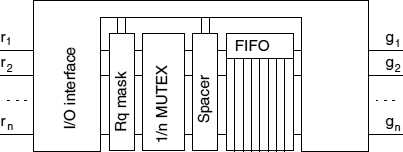
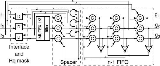
The ordered arbiter (OA), [104] uses the structure shown in Figure 14.4. It uses a FIFO to store grants in the order of request arrival and a request mask to minimize the amount of time when a request that is being granted is staying high, thus blocking the arbiter from its main function. This also maximizes the time when there are no requests pending on MUTEX inputs, thus improving its practical fairness and reducing metastability rate. The latency of such an arbiter in a busy system depends on the speed of FIFO, which can be made fast.
A three-way OA is shown in Figure 14.5. Interface and masking functions are performed by D-elements [102]. A request (r1 for example) propagates to the n-input MUTEX input and further into the first channel of FIFO after arbitration. The left column of C-elements is a spacer, so the FIFO write acknowledgement is indicated at the second column as 0 on the output of the left NOR gate. This value is applied to the C-elements of the spacer, preparing them to accept an all-zero separation word. Only then a high level is set at the output of the upper AND gate and applied to the D-element concluding the second phase of the four-phase handshake protocol. Then the D-element resets the MUTEX input to 0 (releasing MUTEX for the next arbitration), which propagates to the spacer and through the upper AND gate back to the D-element. At this point the value is written into FIFO and a separator word is formed. Then the D-element generates acknowledgement at its left output allowing the value to be shifted into the last FIFO stage. The critical section for the first client begins when g1 is set high (it can be delayed by other values in FIFO). When the client drops its request, the value 0 is generated at the left output of the D-element. This value is applied to the C-element allowing a separator word into the rightmost stage of FIFO (reset g1).
Figure 14.4 Ordered FIFO arbiter.
Figure 14.5 Ordered three-way arbiter circuit.
The time of the MUTEX being blocked is now bounded by a fixed delay τ = 2τC + τNOR + τD, which is small, whereas in an arbiter without a FIFO this delay is determined by the critical section of a client, whose bound is unknown.
One can see that this arbiter implements the simplest priority discipline based on the temporal order of requests. It can be modified to implement a different discipline, for example a LIFO, a FIFO with ‘overtaking’ or a disciple based on a combinational function using the global FIFO state as its primary inputs.
14.5 CANONICAL STRUCTURE OF PRIORITY ARBITERS
In the arbiter structure described below the function of registering the requests is completely separated from the combinational circuit implementing the priority function. Thus, a canonical structure is created which implements the combinational type of priority discipline taxonomy.
In order to be considered for the next grant, one or several requests must arrive before the moment of the request vector registration. This happens either if several requests arrive simultaneously (a low probability event) or if these arrive or stay pending during the critical section in one of the clients (a likely event in a busy system). The priority function can be changed by modifying the priority combinational circuit without altering the arbiter structure. Further, this can be done at initialization time by setting up additional inputs of the priority circuit, thus making the arbiter programmable. Such an arbiter can implement any priority function as opposed to an arbiter with a topologically fixed priority discipline, which is defined by the order of request polling.
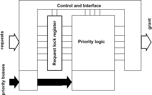
Based on this concept, we construct a static priority arbiter (SPA), using single wires as request inputs, and a dynamic priority arbiter (DPA), whose request inputs are accompanied with buses carrying priority data. The DPA and SPA implement the scalar and vector primary data types of the priority discipline taxonomy correspondingly. In Figure 14.6 both SPA and DPA structures are shown.
Figure 14.6 Static and dynamic priority arbiters. Reproduced from Figure 3, “Priority Arbiters”, by A Bystrov, D.J. Kinniment, and A. Yakovlev which appeared in ASYNC'00, pp. 128–137. IEEE CS Press, April 2000 © 2002 IEEE.
SPA examples include an arbiter whose request lines form several groups, and the priority function always gives a grant to a member of the group with the greatest number of requests. Another example is context dependent arbitration, which gives a higher (or lower) priority to a request that belongs to the group of active requests forming a particular pattern.
A DPA uses dedicated priority buses to receive priority information from clients. The most obvious application of DPA is to detect a request with the highest priority value on the priority bus.
14.6 STATIC PRIORITY ARBITER
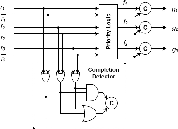
The structure of an SPA originates from the idea described in [104]. It operates in two stages. At the first stage it locks the request vector in a register comprising two-way arbiters (MUTEX elements). At the second stage it computes a grant using a combinational priority module. The separation of arbitration and grant computation functions allows the circuit to achieve truly combinational behaviour. Interface and control logic provides the correct functionality of the device under arbitrary gate delays. A single bit of the lock register is shown in Figure 14.7. It is similar to the request polling block of the token ring arbiter (see Section 13.3). The output of this circuit forms a dual-rail code, in which code words are separated by the all-zero spacer word. This facilitates the design of the priority module as a dual-rail circuit. Note, that for a speed-independent realization the AND gate in Figure 14.8 must be replaced by a C-element, or other appropriate means must be implemented to indicate the reset phase of the signals.
Figure 14.7 Lock register bit. Reproduced from Figure 5, “Priority Arbiters”, by A Bystrov, D.J. Kinniment, and A. Yakovlev which appeared in ASYNC'00, pp. 128–137. IEEE CS Press, April 2000 © 2002 IEEE.
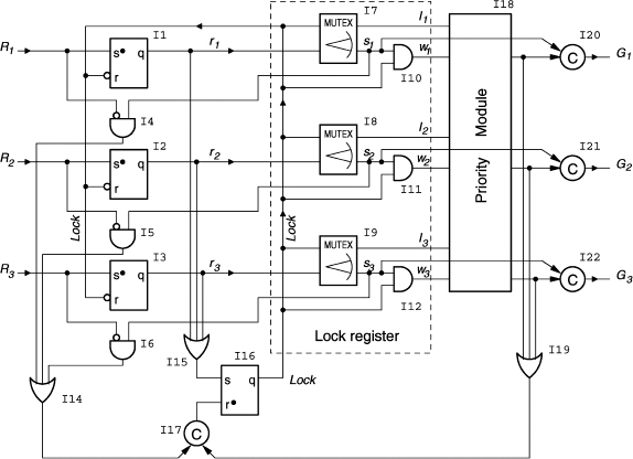
An example of a three-way SPA is shown in Figure 14.7. Let us examine its operation.
The input requests R1…R3 propagate through the set-dominant latches I1…I3, defined by the function ![]() , to the MUTEX elements I7…I9. After at least one of these reaches a MUTEX, a high signal level is formed at the output of the reset-dominant latch I16, defined by
, to the MUTEX elements I7…I9. After at least one of these reaches a MUTEX, a high signal level is formed at the output of the reset-dominant latch I16, defined by ![]()
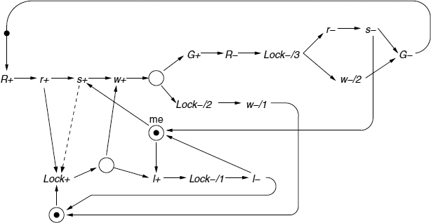
![]() . This signal (Lock) is applied to the upper inputs of MUTEX elements, thus locking the request vector. After the input vector is locked, a dual-rail signal is formed at the inputs of the priority module. The priority module is implemented as dual-rail logic to guarantee that the output signal is generated after the process in the MUTEX elements is settled. The priority module determines which request should be granted and raises the signal at the appropriate output. This signal becomes locked in the output buffer comprising C-elements (I20…I22). After using the resource, the client resets its request. This is detected by I4…I6 and causes switching of I17 and I16, resulting in the resetting of the Lock signal. This resets the input latch, the MUTEX in the channel where the request has been dropped and all input signals of the priority module. Then the priority module outputs and the grant signal are reset. Then low levels are formed at the outputs of I14 and I19, which switches the C-element I17, unblocks I16 and enables processing of the next request. Correct operation of the lock register is crucial for the priority arbiter. An STG in Figure 14.9 shows how the polling cell is made insensitive to the gate delays. This STG describes the behaviour of a single channel, which explains why the indices after R, r, s, l, w and G signal identifiers corresponding to the request channels are not shown.
. This signal (Lock) is applied to the upper inputs of MUTEX elements, thus locking the request vector. After the input vector is locked, a dual-rail signal is formed at the inputs of the priority module. The priority module is implemented as dual-rail logic to guarantee that the output signal is generated after the process in the MUTEX elements is settled. The priority module determines which request should be granted and raises the signal at the appropriate output. This signal becomes locked in the output buffer comprising C-elements (I20…I22). After using the resource, the client resets its request. This is detected by I4…I6 and causes switching of I17 and I16, resulting in the resetting of the Lock signal. This resets the input latch, the MUTEX in the channel where the request has been dropped and all input signals of the priority module. Then the priority module outputs and the grant signal are reset. Then low levels are formed at the outputs of I14 and I19, which switches the C-element I17, unblocks I16 and enables processing of the next request. Correct operation of the lock register is crucial for the priority arbiter. An STG in Figure 14.9 shows how the polling cell is made insensitive to the gate delays. This STG describes the behaviour of a single channel, which explains why the indices after R, r, s, l, w and G signal identifiers corresponding to the request channels are not shown.
Figure 14.8 Three-way SPA. Reproduced from Figure 8, “Priority Arbiters”, by A Bystrov, D.J. Kinniment, and A. Yakovlev which appeared in ASYNC'00, pp. 128–137. IEEE CS Press, April 2000 © 2002 IEEE.
During its operation, the arbiter produces the following traces corresponding to the STG in Figure 14.9. If, at the moment of the Lock setting, the request R is not present, then the trace (Lock+, l+, Lock−/1, l−) is produced, which means that the polling cell has registered a ‘lose’ situation and the output grant has not been issued. If, at the moment of the Lock arrival, the request R is present, then two situations may take place. The first is described by the trace (R+, r+, s+, Lock+, loop:{w+, priority-resolution, Lock−/2, w−/1, Lock+}), which covers the scenario when the request is locked (s+), but the grant G is not issued. This happens if the priority module decides to satisfy a higher priority request in another channel that is not shown. The trace part labeled as ‘loop’ is executed repeatedly until the request R is satisfied. The second situation, in which the priority module satisfies the request R, is described by the trace (R+, r+, s+, Lock+, w+, priority-resolution, G+, R−, Lock−/3, r−, s−, G−). These traces clearly show that a dual-rail code is formed by the polling cell at its outputs w, and l, every time after a Lock+ event. The code words are separated by all zero words (w=0 and l=0), which facilitates the use of a dual-rail priority module.
Figure 14.9 STG of the request lock register. Reproduced from Figure 7, “Priority Arbiters”, by A Bystrov, D.J. Kinniment, and A. Yakovlev which appeared in ASYNC'00, pp. 128–137. IEEE CS Press, April 2000 © 2002 IEEE.
The STG in Figure 14.9 indicates a potential problem in the realization of the request lock register. A scenario is possible in which the request R+ arrives, propagates to the MUTEX input causing r+ and activates s+ which, in this example, is considered to be extremely slow. At the same time r+ triggers Lock+ (dashed arrow) and subsequently l+ (both are fast). This creates a situation when a single request causes an all-lost vector being locked. The latter leads to a deadlock in the system as such a vector produces no priority module output, the C-element I17 (Figure 14.8) never switches to 1 and the Lock signal never resets. However in the practical realization of a two-way MUTEX based upon a cross-coupled latch this scenario is not possible due to the physics of the s+ transition. Once enabled, the voltage of an internal signal (which is the source of s ) begins to change, which results in s+ rather than l+ even if Lock+ is very fast (1 ps in 0.6 μ technology). This very reasonable, in our opinion, timing assumption can be avoided (at the expense of the speed reduction) if the inputs of I15 Figure 14.8 are connected to the MUTEX outputs s1 … s3. This will correspond to the dashed arc in Figure 14.9.
In the arbiter circuit shown in Figure 14.8, the only gate output which is not properly acknowledged is that of the OR gate I15. It can either be considered as part of a complex gate inside the I16 latch, or its delay must be bounded by a reasonable value. Both timing assumptions on the speed of the MUTEXes I7 … I9 and the OR gate I15 can be removed if an additional priority module output is added which represents a ‘nil grant’. This output would go high when an ‘all-lost’ request vector is locked (the priority module input labelled as ‘not possible’ in the truth tables below). The ‘nil grant’ can be used to reset the lock latch I16 (an additional dominant reset input is needed) thus restarting the process of request locking and grant computation.
Figure 14.10 Priority module. Reproduced from Figure 8, “Priority Arbiters”, by A Bystrov, D.J. Kinniment, and A. Yakovlev which appeared in ASYNC'00, pp. 128–137. IEEE CS Press, April 2000 © 2002 IEEE.
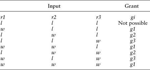
A possible dual-rail realization of the priority module is shown in Figure 14.10. The module produces 1-hot output after the dual-rail input is settled. The output becomes reset to an all-zero input word (separator). The hazard-free priority logic (PL) can be implemented as sum-of-products circuit without inverters. The truth table of this PL shown in Table 14.1 which implements a linear priority system.
Table 14.1 Linear priority function.
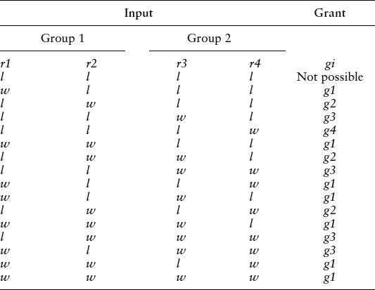
Table 14.2 Priority function supporting groups.
Symbol w in Table 14.1 means ‘win’ and signifies the request locked in the MUTEX register. Symbol l means ‘lose’ and indicates the request which is considered to be absent at the moment of arbitration.
A more complex example of the priority function is shown in Table 14.2. It handles requests that form two groups group1 = {r1; r2} and group2 = {r3; r4}. The higher priority is always given to a group with the largest number of active requests. If the number of requests is equal, then group1 wins. Within a group a request with the lower number has greater priority. This priority function can also be implemented as a sum-of-products hazard-free circuit.
14.7 DYNAMIC PRIORITY ARBITER
A dynamic priority arbiter (DPA) considered in this section performs comparison of the priorities supplied with each request and grants the one with the highest value. Note that the proposed structure may implement an arbitrary priority function, which is ‘encoded’ into the priority module. The structure of a DPA is very similar to the structure of an SPA as shown in Figure 14.6. The difference is that DPA uses additional data (priority values) produced by clients and passed into the DPA through dedicated priority busses. The value on a priority bus is valid only when the corresponding request is present. This creates a problem with speed-independent realization of the priority module as a delayed transition on the priority bus may be interpreted as an incorrect value. Another problem is to design a comparator for k n-bit priority buses which take into account only the values accompanied by a request. Disregarding the priority bus state is a nontrivial task in a speed-independent design, as special means are required to prevent hazards. In both the speed-independent and the bundled-data approaches a special signalling is needed to distinguish the data which have not arrived yet due to the data path delay from the data that will not arrive because the corresponding request is not set. The first problem is solved by using a dual-rail, or a 1-hot code, on the priority buses of the quasi-speed-independent arbiter realization. This is not needed for the bundled-data realization. The second problem is solved by introducing two signals v (‘valid’) and i (‘invalid’) which accompany every priority bus. These signals are generated by the lock register (similarly to w and l signals in the SPA) and propagated through the tree comparator distinguishing the priority value which has not reached the node yet from the absent request.
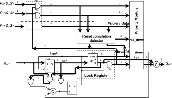
A ‘practically acceptable’ (see previous discussion about some minor delay assumptions) speed-independent DPA realization with 8 requests and 4 request priority values is shown in Figure 14.11. Priority buses carry a dual-rail code, though a design with 1-hot code has also been considered. The lines of the dual-rail priority buses ![]() are encoded as follows:
are encoded as follows: ![]() is the lower bit,
is the lower bit, ![]() is the higher bit,
is the higher bit, ![]() and
and ![]() are complementary bits defined as
are complementary bits defined as ![]() and
and ![]() . Gate arrays in this Figure are labelled as x4 or x8 depending on the number of array elements. If a bus is connected to such an array, then every bus line is assumed to be connected to the gate with the index number corresponding to the index number of the line. The lower part of the DPA schematic is similar to SPA. The upper part, comprising priority buses, AND gate arrays and a reset completion detector is new.
. Gate arrays in this Figure are labelled as x4 or x8 depending on the number of array elements. If a bus is connected to such an array, then every bus line is assumed to be connected to the gate with the index number corresponding to the index number of the line. The lower part of the DPA schematic is similar to SPA. The upper part, comprising priority buses, AND gate arrays and a reset completion detector is new.
Figure 14.11 Dynamic priority arbiter. Reproduced from Figure 9, “Priority Arbiters”, by A Bystrov, D.J. Kinniment, and A. Yakovlev which appeared in ASYNC'00, pp. 128–137. IEEE CS Press, April 2000 © 2002 IEEE.
Several aspects enhancing functionality and improving performance were considered in the design of this arbiter. Arbitration and grant computation are separated, which permits realization of an arbitrary priority discipline. The control flow and the priority data flow are maximally decoupled in the priority module. This permits control signals to run forward without waiting for the slow data if the data are not needed to compute the result. For example, if a single request arrives, then the output of the priority module and the grant are generated almost immediately. Only the done signal waits for the completion of data manipulation, which happens concurrently with a critical section in the client process. Handshake phases in the control and data flow are also decoupled. C-elements are replaced by AND gates where possible and a reset phase of their inputs is indicated by additional ‘reset-done’ detectors.
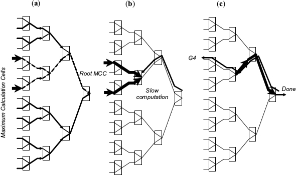
The operation of the control part of the DPA in Figure 14.11 is similar to the SPA. The AND gates on the priority buses are only needed in the speed-independent realization to provide an all-zero separator word for the dual-rail priority module. The separator word (a.k.a. spacer) is indicated by the reset completion detector, which also checks valid-invalid signals for every channel. This detector comprises eight OR gates (one per channel). The inputs of every gate are connected to the lines of a priority bus and to the corresponding valid–invalid signals. Its output goes high as soon as the set phase in the channel begins (the completion of the set phase is indicated inside the priority module). The output goes low only after all inputs are reset establishing the separator word. The outputs of the reset completion detector are connected to the inputs of the reset completion system of the priority module. The priority module uses a tree structure as shown in Figure 14.12 to find the maximal priority value. Every node of the tree is a maximum calculation cell (MCC) which passes on the priority of the selected input, with the exception of the root node (RMCC) which only indicates completion.
Figure 14.12 Accelerated grant generation: (a) fast control propagation; (b) grant propagation during data comparison; (c) early grant output. Reproduced from Figure 11, “Priority Arbiters”, by A Bystrov, D.J. Kinniment, and A. Yakovlev which appeared in ASYNC'00, pp. 128–137. IEEE CS Press, April 2000 © 2002 IEEE.
Every cell has three modes of operation. If it gets ‘invalid’ signals in both channels, then the output ‘invalid’ signal is issued. All input priority data are disregarded and the output priority bus is set to the all-zero spacer word. If only one channel is ‘valid’, then its priority data are transferred to the output bus and the internal comparator is not invoked. If both channels are ‘valid’, then a comparator is used to compare the priority values and the greatest is propagated to the output. In the last two cases the output ‘valid’ signal is generated. The control ‘valid’ signal is permitted to propagate through the tree structure without waiting for the corresponding data. As a result these signals reach the root node very quickly and may even cause the RMCC to generate a primary grant. This happens if the RMCC receives a ‘valid’ signal in one channel and ‘invalid’ in the other. Further, such an accelerated grant may start propagating backwards if the nodes it propagates through do not need data to make a decision. Synchronization with datapath takes place only if the priority value is needed at the given MCC to decide to which MCC port the grant should be forwarded. This acceleration technique is illustrated in Figure 14.12. The nodes of the tree-type maximum calculation priority module are depicted as rectangles. Thick lines show propagation of the priority data. Thin dotted lines depict active ‘valid’ signals and continuous lines depict active ‘invalid’ signals. Arrows show the direction of signal propagation at the given stage. After ‘valid’ and ‘invalid’ control signals are produced by a request lock register, they begin to propagate through the maximum calculation priority module as shown in Figure 14.12(a). Their propagation is faster than the propagation of the priority data. A primary grant in Figure 14.12(b) is generated by the root node without waiting for data, because having one channel ‘valid’ and another ‘invalid’ is sufficient to decide which to grant. Then the primary grant begins reverse propagation to the nearest node which has both channels ‘valid’. Only a node performing data comparison can delay grant propagation. After finishing the computation, the node permits grant propagation and at the same time transfers the maximum priority value to the output priority bus, as shown in Figure 14.12(c). This Figure illustrates that a grant can be released before priority data reaches the root node. This acceleration technique is similar to that used in a low-latency tree arbiter [82]. The difference is that in the described system slow events are associated with dataflow.
To minimize latency the dataflow and the control part (‘valid’–‘invalid’ signals) are maximally decoupled. Synchronization is performed only when the data are needed to make decision. This results in better performance due to more concurrency. The accelerated propagation of control and grant signals does not indicate the set phase on the priority bus. Without this, one cannot guarantee a proper indication of the next phase, which is a reset. This problem is solved by using dual-rail (or 1-hot) circuits as comparators incorporated in MCC. As a result, a value on the priority bus at the root node becomes a code word (dual-rail or 1-hot) after the set phase on all ‘valid’ buses is completed. A completion detector in the root node generates a ‘data done’ signal, which is used to generate the output done. Additional signals ‘reset done’ indicate the reset phase on ‘valid’–‘invalid’ lines and priority buses and allow replacement of C-elements by the faster AND gates in the node circuits. This also accelerates the resetting of the priority module because the control signals causing the reset are propagated without any synchronization at this stage (the cause is separated from the indication). The described delay-independent DPA with dual-rail priority busses has been implemented using an AMS 0.6 μ toolkit and Cadence CAD tools. After the design is initialized by applying the Reset signal, the request R0 is set. The arbiter replies with the grant signal G0 almost immediately (4.94 ns). It does not wait for the priority data P0<0:3> to be set, as it is not required to generate the grant. The acceleration technique used in the priority module ‘almost’ disregards priority data when the output can be computed without it. An accelerated generation of the primary grant g0, can be done in 2.74 ns after V and I signals are set. The completion signal done is produced much later, when the propagation of data is finished. When many requests are pending and data comparison is performed in every level of the priority module the latency is increased to 7.63 ns.
Further speed improvements can be achieved by applying reasonable timing assumptions as shown in [87].
Synchronization and Arbitration in Digital Systems D. Kinniment
© 2007 John Wiley & Sons, Ltd

