
A microcontroller-controlled LED inspired by various LED Throwies, blinking LEDs, and similar Instructables By Alexander Weber
Inspired by many LED Throwies and other LED projects on Instructables, I wanted to do my version of an LED controlled by a microcontroller.
The idea is to make the LED blinking sequence reprogrammable with light and shadow, e.g., you could use your flashlight. You can see a video that demonstrates how to reprogram it here: http://9600baud.blip.tv/file/198088.
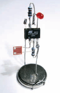
Figure A: The completed programmable LED
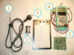
Figure B: 1. Soldering iron 2. Solder 3. Solderless breadboard 4. Multimeter 5. AVR programmer
1. How it works
An LED is used as a visible output. For input, I used an LDR (Light Dependent Resistor). The resistance of the LDR changes as it receives more or less light. The resistor is then used as analog input to the microprocessor’s ADC (Analog to Digital Converter).
When programmed with the software that I introduce later, the controller has two modes of operation: one for recording a sequence, the other for playing back the recorded sequence.
Once the controller notices two changes of brightness within half of a second, (dark-brightdark or bright-dark-bright), it switches to recording mode. In recording mode, the input of the LDR is measured multiple times a second and stored on the chip. If the memory is exhausted, the controller switches back to playback mode and starts to play the recorded sequence.
As the memory of this tiny controller is very limited, 64 bytes (yes, bytes!), the controller is able to record 400 bits. That is enough space for 10 seconds with 40 samples per second.
2. Tools and materials
Tools (Figure B)
![]() Soldering iron
Soldering iron
![]() Solder
Solder
![]() Breadboard
Breadboard
![]() AVR programmer
AVR programmer
![]() 5V power supply
5V power supply
![]() Multimeter
Multimeter
Materials (Figure C)
![]() 1K resistor (2)
1K resistor (2)
![]() LDR (Light Dependent Resistor) such as the M9960 (1)
LDR (Light Dependent Resistor) such as the M9960 (1)
![]() Low-current LED, 1.7V, 2mA (1)
Low-current LED, 1.7V, 2mA (1)
![]() Atmel ATtiny13V, 1KB flash RAM, 64 Bytes RAM, 64 Bytes EEPROM, [email protected] (1)
Atmel ATtiny13V, 1KB flash RAM, 64 Bytes RAM, 64 Bytes EEPROM, [email protected] (1)
![]() CR2032 battery, 3V, 220mAh (1)
CR2032 battery, 3V, 220mAh (1)
![]() Some hookup wire
Some hookup wire
Software
![]() Eclipse (optional)
Eclipse (optional)
![]() CDT plugin (optional)
CDT plugin (optional)
![]() GCC-AVR
GCC-AVR
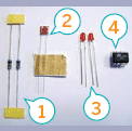
Figure C: 1. Two 1K resistors 2. Light Dependent Resistor 3. Two LEDs 4. Atmel ATtiny13V
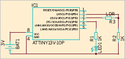
Figure D: Schematic
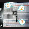
Figure E: 1. Wire to positive voltage 2. IC socket 3. Wire to ground
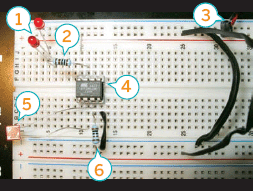
Figure F: 1. Low current LEDs 2. Resistor 1K 3. Power supply 5V 4. ATtiny13V 5. LDR 6. Resistor 1K
Costs overall should be below $5 without tools.
I used the ATtiny13V because this version of this controller family is able to run at 1.8V. That makes it possible to run the circuit with a very small battery. To have it run for a very long time, I decided to use a low current LED that reaches full brightness at 2mA.
3. Schematic
The schematic for this circuit is shown in Figure D.
Note: The AVR’s reset input is not connected. This is not the best practice. It would have been better to use a 10K pull-up resistor. But it works fine for me without and it saves a resistor.
To keep the circuit as simple as possible, I used the AVR’s internal oscillator. That means we avoid having to include a crystal and two small capacitors. The internal oscillator lets the controller run at 1.2MHz which is more than enough speed for our purpose.
If you decide to use another power supply than 5V or to use some other kind of LED, you have to calculate the value for the resistor R1. The formula is:
R = (Power supply V - LED V) / 0.002A = 1650Ω (Power supply = 5V, LED V = 1.7V).
Using two low current LEDs instead of one, the formula looks like this:
R = (Power supply V - 2 * LED V) / 0.002A =
800Ω
The value of the resistor R2 depends on the LDR you choose. 1KΩ works for me. You may want to use a potentiometer to find the best value. The circuit should be able to detect light changes in normal daylight. To save power, PB3 is only set to high when a measurement is made.
4. Assemble on a prototype board
You should first set up the circuit on a breadboard and test it out. That way, you can assemble all parts without having to solder anything. Figures E and F show how to put it together on a breadboard.
5. Program the circuit
The controller can be programmed in different languages. Popular programming languages include Assembler, BASIC, and C. I used C as it matches my needs the best. I was used to C ten years ago and was able to revive some of the knowledge (well, only some…).
To write your program, I recommend Eclipse with the CDT plugin, shown in Figure G. Get eclipse from www.eclipse.org and the plugin from www.eclipse.org/cdt. However, you can use whatever source code editor you are comfortable with.
For compiling C language to AVR microcontrollers you will need a cross compiler. Lucky as we are, there is a port of the famous GCC (GNU Compiler Collection). Windows users can download WinAVR from http://winavr.sourceforge.net. If you are on Linux, you should install the avr-gcc, avrbinutils, and avr-libc packages (these packages are available for many Linux distributions). On Mac OS X, first install MacPorts (www.macports.org), then use MacPorts to install avr-gcc, avr-binutils, and avr-libc.
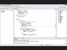
Figure G: Eclipse with the CDT plugin
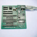
Figure H: AVR ISP programmer
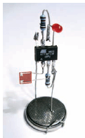
Figure I: The assembled project
For more information on the GNU AVR tool chain, see www.avrfreaks.net/wiki/index.php/Documentation:AVR_GCC.
After you compile the source code, you have to transfer the resulting hex file to the controller. That can be done by connecting your PC to the circuit using an ISP (In-System Programmer) or by using a dedicated programmer that you can drop the chip into. I used a dedicated programmer so I wouldn’t have to wire up the header pins needed to connect the circuit to the programmer. The drawback is that you have to swap the controller between the circuit and the programmer every time you want to update your software. My programmer, shown in Figure H, comes from www.myavr.de and uses USB to connect to my notebook. There are many others around and you can even build one yourself. For example, Adafruit Industries (www.adafruit.com) sells the USBtinyISP AVR programmer kit.
User Notes
Guilherme Souza says: If you make a lot of those, would they interact?
Alex replies: Yes, they would. Take a look at my other instructable for an example: www.instructables.com/id/Synchronizing-Fireflies
For the transfer itself I used AVRDUDE, which is part of the WinAVR distribution (you can install the AVRDUDE under Linux or MacPorts). Here’s an example of how you might invoke AVRDUDE:
avrdude -F -p t13 -c avr910 -P com4 -U flash:w:flickled.hex:i
Check the documentation for your AVR programmer and for AVRDUDE to determine the correct commands.
Note: You can download the source code, main.c, from this Instructable’s web page (www.instructables.com/id/Programmable-LED). The compiled hex file, flickled.hex is also available there.
6. Soldering
After you get the circuit working on the breadboard, you can solder it.
Warning: Do not solder directly to the battery. You should construct a battery holder out of wire and use the weight of the circuit and some creative bending to ensure contact.
You can do this on a PCB (printed circuit board), on a prototype board, or even without a board. I decided to do it without as the circuit consists only of a few components. Figure I shows the completed project. If you are not familiar with soldering I recommend that you search online for soldering tutorials and videos first.
My soldering skills are a bit rusty but I think you get the idea.
I hope you enjoyed it.
Alex Weber lives in Hamburg, Germany, and develops software by day and tinkers with electronics by night. Visit him at http://tinkerlog.com.