

3-Axis CNC Milling Machine
This DIY computer-controlled milling machine puts the power of computer controlled machining at your disposal By Tom McWire
Here’s how to make a computer-controlled milling machine. This puts the power of computercontrolled machining into the hands of the average human. Small enough to set on the desk but scalable to any size. As inexpensive as possible without sacrificing accuracy (too much). Almost all the parts can be purchased in local retail stores. And above all, it’s CHEAP, so you can be up and running for well under $200. With it, you can do 2-dimensional engraving and PC board etching, and 3D milling and modeling in foam, wood, plastic, and other soft materials.
Note: You should also check out the YouTube movie that shows how to build this Instructable: www.youtube.com/watch?v=6drMZqmyXQc.
Note: Be sure to check out my “Easy-to-Build CNC Mill Stepper Motor and Driver Circuits” Instructable for details on how to make this machine go: www.instructables.com/id/EJ3KFVBF5R8QRL3.
1. The frame
The frame needs to be two things:
1) A flat base that you can mount everything on horizontally
2) A goose neck of some kind to hold the Z axis (the part with the motor tool that goes up and down) firmly in place.
For my frame, I used 1" pipe just for fun, but as it turned out it was pretty handy too. When I needed to make adjustments I could just tap it with a hammer. As you can see in Figure B, the post that holds the Z axis doesn’t have to be in the center. It just needs to be firm and the water pipe does a good job of that. Later, after you are sure all the pipe joints are in the right place, you can add a drop of thread sealer to the joints and it will be a good solid structure.
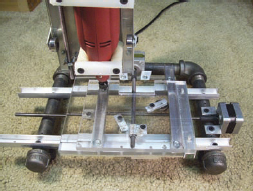
Figure A: The completed machine

Figure B: The frame

Figure C: X-stage rails
2. The x-stage rails and motor
It’s time to add the rails for the x-axis stage. These rails are 3/4” U-channel aluminum that you can get from the hardware store. Put a washer under each end to space the rail off the pipe just a bit. Don’t worry about the rails being perfectly parallel. You’ll see why later.
Next, mount the stepper motor with a bracket like you see in Figures C and D. Connect a length of 1/4” by 20" threaded rod to the motor shaft with a short piece of rubber hose (1/4” inch fuel line). Now you’re ready to set the movable part of the x-axis (the stage).
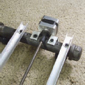
Figure D: Closeup of the rails

Figure E: Plexiglas mounted to a U-channel

Figure F: Bearings mounted to a piece of aluminum

Figure G: Another piece of aluminum wrapped around a coupling nut
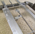
Figure H: Plexiglas, bearings, and coupling nut in place
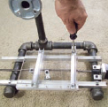
Figure I: Making the y-stage

Figure J: Assemble the Plexiglas, bearing, and coupling nut
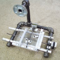
Figure K: The y-stage
3. X-it stage right
Take a piece of plastic (I used Plexiglas, shown in Figure E) or metal, something strong and flat and mount a piece of the U-channel to it.
Now comes the tricky part. The round object shown in Figure F is a bearing. You can get them out of motors or buy them at a hardware store. Mount it to a short piece of aluminum as shown.
Next, take a 1/4” coupling nut (a long nut) and wrap it with aluminum as shown in Figure G. The bearing will hold the x-stage to the x-rail, and the coupling nut will allow the motor to run the stage back and forth (Figure H). It wouldn’t hurt to grease the skids and the nut a little too.
Note: You can see a video on making the bearing fixture at www.youtube.com/watch?v=Y6vDllrRSDw.
4. The y-stage
The y-stage is just like the x-stage but turned 90 degrees. Mount two rails and a motor on the x-stage as shown in Figure I and then take another piece of flat material and a U-channel and make the moving y-stage. Make the little bearing assembly and a coupling nut for it too (Figure J). When you’re done it should look like Figure K.
5. Zee z-axis
Again, we are going to reproduce the x- and y-stage to create the z-axis stage. But first, take a flat piece of material; I used a piece of white Plexiglas. Mount some rails and a motor to it (Figure L). Then make a moving stage piece with a U-channel and a roller bearing. We’ll do something a little different with the nut (Figures M-N). The four posts you see on the stage will hold the motor tool. Since this stage is going to move up and down the weight of the motor tool will make it want to come off of the rails so lets add a few more roller bearings to each side to keep it together (Figures O-P).
6. Get it together
Now we slap the motor tool into the z-stage (Figure Q). Then it’s time to mount the stage to the frame as shown in Figures R and S. And there you have it. This is the mechanical structure. From here we will need to hook up the stepper motors to a controller and get some software running on the computer (see my “Easy to Build CNC Mill Stepper Motor and Driver Circuits” Instructable for details on how to make this machine go: www.instructables.com/id/EJ3KFVBF5R8QRL3).
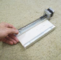
Figure L: Making the z-stage

Figure M: Adding the posts

Figure N: Another view of the posts
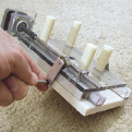
Figure O: Attaching roller bearings
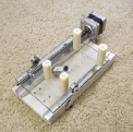
Figure P: The z-stage

Figure Q: Attaching the motor tool to the z-stage
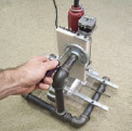
Figure R: Mounting the tool to the frame

Figure S: The completed mechanical structure

Figure T: Milling a PC board
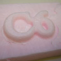
Figure U: Carving a 3D object out of foam
7. What does it do?
If you were interested in this project it’s likely you have already seen what can be done with an 3-axis (XYZ) computer-controlled milling machine. What is surprising is what kind of accuracy you can get out of this thing after you tinker with it a little bit. Make sure all the rails are held firm and straight. Tighten the roller bearings so the stage doesn’t shift.
I use it to make PC boards (see Figure T). It’s also good for engraving name tags and signs. And it’s pretty exciting to see it carve a 3D object out of a block of foam (see Figure U) or plastic.
Note: There’s a lot to learn about the software. Some venders offer package deals of motors, drivers, and software. That makes it easier but you pay for it. I have been using KCAM from www.kellyware.com. You can run the demo for 30 days or buy it for $100. I think it works pretty good for the price. Look there, and you will get some idea of what it takes to run the motors from a computer.
8. Engraving
I put the machine back together after making the Instructable and I did some engraving and made a PC board.
Cutting plastic is no problem but when I tried a PC board, the bit went a little too deep on the left side of the board and took out all the finer traces. This is when you start tweaking it. Just take some aluminum foil and put it under the rail of the y-axis. As the stage travels left to right, the height of the bit should stay the same.
Notice in Figure T I’m just holding the material down with masking tape. What I like about this Instruct able is that it’s easy to fix these kinds of problems because it’s all made from simple elements.
Tom McWire is an engineer, inventor, and artist who loves to work with machines and inspire people to have fun with technology. See more of him at www.tommcguireart.com.