
Wireless Home Router with Analog Utilization Meter
Using an old analog gauge to display network information in a more human readable form
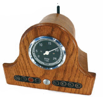
Figure A: The completed router
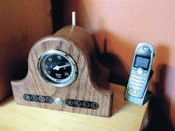
Figure B: The router in action
I grew up in and around boats making wiring looms and control panels, and have a collection of gauges and dials that would normally be connected to small marine diesel engines.
Note: This Instructable was among many that were featured in The New York Times article “In a Highly Complex World, Innovation from the Top Down,” by G. Pascal Zachary, published July 29, 2007. See www.instructables.com/forum/TW6BU3YF4R3E4Y9 for more details.
Today I work as an interaction designer creating interfaces that simplify complex data. As such, I like re-using the old analog gauges to display network information in a more human readable form… tying my past to the present to some degree.
I used a 3" rev counter—a simple clean design—that came off one of the boats my dad owned when I was a kid. I wired it into a wireless router I had lying around at work.
The rev counter is a rough approximation of the traffic between my home network and the Internet.
1. How it works—an overview
There are many ways to find out how much bandwidth is being used. This being the first pass at visualizing the usage, I opted to simply use the uplink LED as an indication of the amount of traffic passing between my home and the Internet.
This has some serious limitations. I do not know whether the hardware (Broadcom chipset) or firmware (DD-WRT) contains the sampling algorithm that drives the LED (it’s probably the chipset).
Here’s the first issue: an LED must be on for around 30ms for the human eye to register it properly. Networking packets are much much shorter than this. So the router must do a little math and translate real network traffic into slower LED blinking. So there is a sampling loss, and the LED is a rough approximation of the actual traffic.
I must boost the 3.3v that drives the LED up to 14v required for the rev counter (most automotive dials and meters like this are linear 0-12v or 14v). For this I used a basic op-amp circuit (Figure C shows a rough sketch of it). Without some swanky digital-toanalog conversion I again lose a lot of resolution.
The result is not a very good representation of the traffic bandwidth being used, but the further I got into the project, the more it became an interesting object of art and less a solution to the original problem.

Figure C: A sketch of the circuitry for this project
Note: I’ve been working with the guys from DDWRT (http://dd-wrt.com/dd-wrtv2/index.php). If your router supports it, I highly recommend you upgrade your current software to this feature rich open source firmware.
2. Front panel
I desoldered the LEDs from the router’s PCB and routed them out to the front with a ribbon cable and header connector.
Then I designed an overlay in Omnigraffle on a Mac, printed it to an overhead projector transparency with a laser printer (you can get transparencies for ink jet printers as well). I also chiseled out a channel for the overlay so it had a nice inset look.
I fell in love with a power switch from a piece of development hardware at work, unfortunately it was a momentary switch so I spent quite a lot of time retrofitting a NO (normally open) microswitch with a blue LED glued to the tip.
I routed the edge of the large front panel section (see Figures D and E). Figure F shows the rev counter attached to the front panel. You can see the bezel in Figures G and H.

Figure D: 1. A fish tank pump that blows away the dust as you cut

Figure E: 1. Rev counter from a Lister Perkins 30 HP marine diesel engine 2. A damn good looking front power switch 3. Inset for the front decals
3. Op-amp circuit
There are two stages between the LED on the main router board and the rev counter:
A. Isolate the op-amp circuit from the router board. This is done with a buffer in the form of a 74HC04, a hex inverter with gates that will not draw any current from the router and will output a signal based on the inverse of its input. This guy comes with 6 gates, so if you want to get the same output signal as the input signal you tie the gates back to back.
Note: I had an intermediary stage that was designed to smooth the square wave signal driving the LED to a nice analog rising/falling charge to the rev counter. However, the mechanics of the counter provided the smoothing I wanted. So, in some of the diagrams you’ll see an RC Low pass filter.

Figure F: The back of the panel face with the meter and indicator LEDs attached
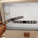
Figure G: Front decal design
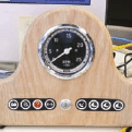
Figure H: Paper prototype of the front decals

Figure I: The op-amp circuit for converting the network activity LED into an analog signal

Figure J: 1. I’m very fortunate to have access to a lab equipped with every imaginable tool you could possibly need for designing a project like this 2. Linksys router board. Although I ended up using a different one from Buffalo, I used the Linksys router to get a flashing LED for testing the circuit 3. Solderless breadboard

Figure K: 1. Trimpot for tuning the gain on the amp 2. Input pins 3. Op-amp 4. Hex inverter/buffer 5. Output 6. Twelve volts in; for testing purposes I had to mess around with the Vcc for the hex inverter. I ended up with its rail being around four volts 7. Twelve volts in
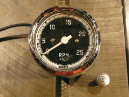
Figure L: The rev counter and button
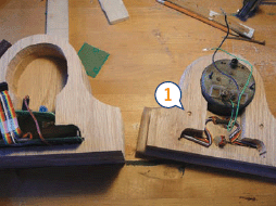
Figure M: 1. I drilled right through this section and in about a 1/4” to the back of the front panel, then set in some dowels. I then glued this section to the rest on the left hand side in this picture. This gave me two nubs that aligned when putting the case together.

Figure N: Drilling with a Forstener Bit
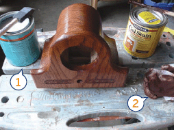
Figure O: 1. I sealed the wood with a semi-gloss finish 2. I used this to rub the stain in and wipe off the excess
B. The op-amp. I chose a very old chip, the LM 741, that worked but came with a lot of limitations that drastically affected the design. The rev counter never goes to zero, and the range seems to hover around the center of the dial. Limitations of the opamp. It’s a lesson learned, and in future, I’m going to improve this circuit to have a wider range of output.
Figures I, J, and K show the design of the circuit progressing from paper, to solderless breadboard, onto a prototyping board.
4. Parts & tools
Parts list
![]() Rev counter (Figure L): It’s a VDO meter that still had some fishing boat gunk on it. Testing showed its characteristics were that it liked to be fed a linear input of 0-12v.
Rev counter (Figure L): It’s a VDO meter that still had some fishing boat gunk on it. Testing showed its characteristics were that it liked to be fed a linear input of 0-12v.
![]() Router: The smallest PCB form factor in the market that I found was from Buffalo
Router: The smallest PCB form factor in the market that I found was from Buffalo
![]() Software: I installed the DD-WRT open source router firmware (www.dd-wrt.com/dd-wrtv2/index.php). This isn’t strictly necessary but I can’t prop this software enough.
Software: I installed the DD-WRT open source router firmware (www.dd-wrt.com/dd-wrtv2/index.php). This isn’t strictly necessary but I can’t prop this software enough.
![]() Wood: Oak plank from local hardware supply
Wood: Oak plank from local hardware supply
![]() Solderless breadboard for testing
Solderless breadboard for testing
![]() Protoboard/perfboard for the final op-amp circuit
Protoboard/perfboard for the final op-amp circuit
![]() Op-amp: LM 741
Op-amp: LM 741
![]() Buffer: 74HC04 hex inverter
Buffer: 74HC04 hex inverter
![]() Decal: transparent stock for laser/inkjet
Decal: transparent stock for laser/inkjet
Tools
![]() Electronics: Soldering iron, multimeter (if you have an oscilloscope, use it for fault testing)
Electronics: Soldering iron, multimeter (if you have an oscilloscope, use it for fault testing)
![]() Carpentry: scroll saw, table saw, carving chisel, mortising tools, glue, and dowels
Carpentry: scroll saw, table saw, carving chisel, mortising tools, glue, and dowels
![]() Decal: any drawing application such as Omni-Graffle, Adobe Illustrator, or Microsoft Paint
Decal: any drawing application such as Omni-Graffle, Adobe Illustrator, or Microsoft Paint
![]() Most of your digits still attached
Most of your digits still attached
5. The case
This is a very organic way to make a case, the right way would be to use some cheap chipboard or pine and veneer it with a nicer wood. In solidarity with the unskilled, I layer-caked the case up from individual sections cut from a plank.
I milled out the areas needed for the rev counter, router PCB board, op-amp protoboard, and added a channel for the aerial coax to the rear.
I marked each section from a template, cut with the scroll saw, glued, and sanded. Then I finished it with a dark stain and semi gloss.
Figures M, N, and O show various steps in assembly. The following video shows more detail: video.google.com/videoplay?docid=3821193407635705452.
User Notes
Pauric, author of this Instructable, in reply to a question from Instructables member Mourtegoul as to whether the op-amp could be replaced by some components tied to the square wave output that drives the activity LED: Very true, there is any number of solutions to the problem. Some suggested a microcontroller. The op-amp works, and I will look at a simple transistor. The thing to think about is smoothing; with a flat out square wave driving the meter you will notice every little blip, I wanted some form of cumulative gain. Even with the op-amp giving me the desired output, it still swings a lot.
Pauric O’Callaghan says: “Design is the art of deleting the non-essential. Making and hacking skills allow us to re-design products to meet our needs and desires while removing unwanted or superfluous functionality.”