
Turn off a TV in style By Jacob McKenzie
This TV-B-Gone uses a 9V battery to send its signal through a matrix of 20 infrared (IR) LEDS. This extends the working range of the device to about 90 feet (line of sight). Using this in a regular-sized room, you are pretty much guaranteed to zap the TV no matter where you point it.

Figure A: The Ultra TV-B-Gone.
1. Get the stuff
You won’t need much to build this; here is a list of the materials shown in Figure B.
![]() TV-B-Gone (keychain version)
TV-B-Gone (keychain version)
![]() one 2N3904 Transistor (if you have any transistors around, experiment with what you have—it will probably work)
one 2N3904 Transistor (if you have any transistors around, experiment with what you have—it will probably work)
![]() one 9V battery
one 9V battery
![]() one 9V battery holder
one 9V battery holder
![]() 20 IR LEDs
20 IR LEDs
You’ll need these tools as well:
![]() Soldering iron
Soldering iron
![]() Some electronics solder Desoldering pump
Some electronics solder Desoldering pump
![]() Hobby knife
Hobby knife
![]() Pliers
Pliers
![]() Wire cutters and strippers
Wire cutters and strippers
If you don’t have the TV-B-Gone, you can get one at the Maker Shed: www.makershed.com.
2. Modify the TV-B-Gone
Take apart the TV-B-Gone and examine the board. Notice that it uses two sets of batteries. The two 3V batteries (Figure C) on top drive the LEDs and the bottom 3V battery (Figure D) powers everything else. To save a little space you need to move the 3V battery to the top holder and use the 9V battery in place of the 6V supply.
To get rid of the lower battery holder you have to use a sharp cutting tool to break the connection on the right side of the top battery holder, as shown in Figure E. Next, solder a wire on the left side from the big pad through the hole that is right next to it (Figure F). Now you can remove the lower battery holder and move the bigger 3V battery to the top holder.
3. Add wires
Remove the IR LED that is on the TV-B-Gone and replace it with a pair of wires. Then solder wires for ground and +9V in the two places shown in Figures H and I.
4. Make the LED array
Start with two LEDs and decide which direction you will stitch. Bend the inside lead towards the second LED and solder it (Figures J and K). Repeat until you have a string of four LEDs (Figures L and M). Then repeat the entire process five times.
Now bend the leads of one set to the side and attach another set between the two bent leads (Figure N). Repeat this until you have filled out the entire grid (Figures O and P).
NOTE: Always check the polarity of the LEDs you are soldering. This configuration creates five parallel blocks of four LEDs in series.
5. Complete the circuit
If you are looking at the flat side of a 2N3904 with the pins down, the pins are called Emitter, Base, and Collector from left to right. Attach the Collector and the LED connection from the TV-B-Gone PCB to the negative side of the LED array (see Figure Q).
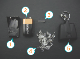
Figure B: 1. 9 volt battery box 2. 9 volt battery 3. 2N3904 Transistor 4. 20 IR LEDs 5. TV-B-Gone

Figure C: 1. The 6 volt power source

Figure D: 1. The 3 volt power source
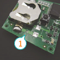
Figure E: 1. Cut the solder trace here. Be sure to completely break the connection.
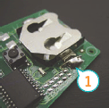
Figure F: 1. Solder a wire from this side to the other side of the board
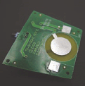
Figure G: After removing the bottom battery holder
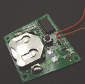
Figure H: Replace the existing infrared LED with a pair of wires

Figure I: 1. Positive 9 volts 2. LED negative 3. LED positive 4. Ground

Figure J: 1. Solder here; note that all LEDs must be oriented in the same direction
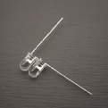
Figure K: A pair of connected LEDs
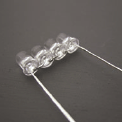
Figure L: Four in a row

Figure M: Note that they are all oriented the same way

Figure N: Eight-up

Figure O: Viewing the array from the top
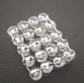
Figure P: Viewing the array from the bottom
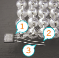
Figure Q: 1. Collector, 2. Base, 3. Emitter

Figure R: Connecting the Base and Emitter
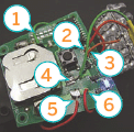
Figure S: 1. To battery negative 2. To transistor base 3. To LED array negative 4. To Transistor emitter 5. To LED array positive 6. To battery positive
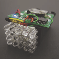
Figure T: The completed TV-B-Gone

Figure U: Completed TV-B-Gone showing 9 volt battery pack

Figure V: Completed TV-B-Gone showing 3 volt battery pack
Now, connect the Base to the LED+ wire. Then connect the emitter to ground on the circuit board as shown in Figure R.
Wire the positive side of the LED array to the 9V supply. Finally, connect the ground and 9V wires from the PCB to the 9V battery clip. Figure S shows the connections.
You’re done! To keep it all together, attach the LED array and PCB to the battery box (use doublestick tape or whatever you have handy).
Jacob McKenzie is a mechanical engineering student at UC Berkeley and former MAKE magazine intern. He thinks bicycles and Lagrangian mechanics are both awesome.
User Notes
Mitch Altman, creator of the TV-B-Gone, says: R2, R7, and R8 are pull-up resistors that are used for some versions of TV-B-Gone, but not others. Most versions of TV-B-Gone use microcontrollers that have its firmware (i.e., the controlling software) manufactured into the chip (these are called Masked-ROM chips)—these also have built-in pull-up resistors in the chip. Some versions of TV-B-Gone use a One-Time-Programmable (OTP) microcontroller (the firmware is programmed into the chip after the chip is manufactured), and since these OTP chips do not have built-in pullup resistors, they need to be added externally. One pull-up (R2) is for the switch. One pull-up (R7) is for jumper R5, and the other (R8) is for jumper R6. The R6 jumper isn’t used for anything, but the R5 jumper tells the TV-B-Gone whether to use its North American or European database. If R5 is 15KΩ or less, the TV-B-Gone uses its European database, otherwise it uses its North American database.
The first versions of TV-B-Gone did not have a visible indicator light. As Jake said, the TV-B-Gone works fine without it. If you have one of these old TV-B-Gone remotes and would like a visible indicator, then you can add Q2 (2N3904), R3 (1K), R4 (any value from 270 through 1k), and D2 (any visible LED).