
A simple robot that uses a switch as a sensor and stands on only two wheels By Mohammad Yousefi
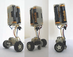
Figures A-C: Three views of our ingenious Balancing Robot. Note the use of a button cell battery and momentary switch as the balance sensor.
This is a simple robot that uses a basic switch as a sensor and stands on two wheels by means of an inverted pendulum mechanism. When the robot is going to fall, the motor turns on and moves the bot in the direction of the fall. The robot’s motor generates restoring torque, and when the restoring torque is equal to the falling torque, the robot becomes balanced.
1. You will need the following parts and tools
![]() A small electric motor
A small electric motor
![]() An axle
An axle
![]() Wheels (2)
Wheels (2)
![]() AA battery holders (2) and batteries (4)
AA battery holders (2) and batteries (4)
![]() A button cell battery (can be a dead one)
A button cell battery (can be a dead one)
![]() A SPDT (single pole double throw) switch with a metal lever (aka a momentary switch)
A SPDT (single pole double throw) switch with a metal lever (aka a momentary switch)
![]() A toggle switch for the on/off power switch
A toggle switch for the on/off power switch
![]() Some plastic strips to make robot body parts
Some plastic strips to make robot body parts
![]() Some gears (or a motor with a gearbox)
Some gears (or a motor with a gearbox)
![]() A small nail/brad (used as an attachment pin)
A small nail/brad (used as an attachment pin)
![]() Hook-up wire
Hook-up wire
![]() Soldering iron and solder
Soldering iron and solder
![]() Glue/epoxy
Glue/epoxy
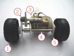
Figure D: The robot’s drive train—1. Wheels 2. Gear train 3. Small DC motor 4. Axle 5. Plastic axle brackets glued to motor
2. Motor, gears, shaft, and wheels
In this step, you must make a drive system to move your robot. You can make it easily by adding some gears to a small DC motor, then connect it to an axle and two wheels (Figure D). You could also use a readymade motor with gearbox. For my gear train, I used a 12.16 gear ratio (32*38:10*10).
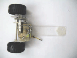
Figure E: Attaching the robot’s “neck” to the drive train with glue and wire
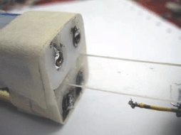
Figure F: Attaching the two AA battery holders, with tape and glue, to either side of the plastic “neck”
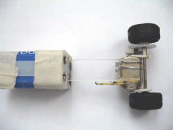
Figure G: The basic bot assembly. The tape is used only to hold parts in place while glue is drying.
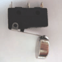
Figure H: The momentary switch with button cell soldered to lever to use as touch-trigger
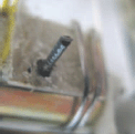
Figure I: Heated nail pressed into plastic to make mounting-pin for sensor switch
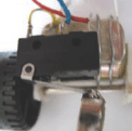
Figure J: Sensor switch installed
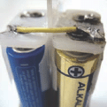
Figure K: Wiring the battery packs together (positive to negative)
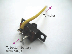
Figure L: Power switch wiring
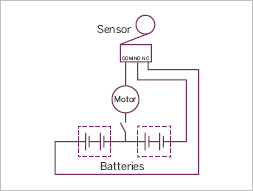
Figure M: Balancing Robot Circuit Diagram
3. Attach the robot’s neck and head
Use glue to attach a strip of plastic (approx. 2-3/4” long) to the motor. Then put some glue on one side of the battery holders and attach them so that they are flush with the top of the plastic material. The battery holders act as a “head” for the robot.
4. Making the sensor
Solder a button cell battery to the SPDT momentary switch. This is the kind of switch you can scavenge from an old computer mouse (Figure H). The battery is only used as a weight/trigger, so it can be a dead one. Heat the nail head over a flame until it’s hot and press it into the plastic sheet glued to the motor in a position so that, when the robot stands vertically, the button cell will touch the ground (when the sensor switch assembly is attached to this nail pin you’ve made). Cut any excess length on the nail/pin (Figure I). Then attach the sensor switch to the pin with glue (Figure J).
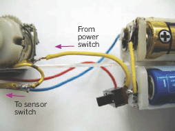
Figure N: Wiring arrangement (one side)
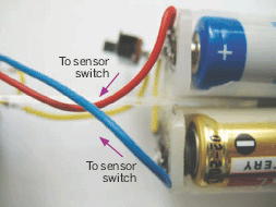
Figure O: Wiring arrangement (other side)
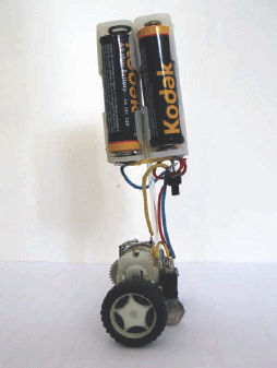
Figure P: Another view of the finished bot
5. Connecting the switch
Solder a wire from the positive pole of one of the battery holders to the negative pole of the other holder and attach the toggle switch to it (Figure K). Next, attach the other side of the switch to the motor (Figure L).
6. Wiring
Now it’s time to solder up the robot’s circuit wires. Note that you must solder the wires in such a way that the robot moves toward the direction where it naturally wants to fall. The photos of the wiring may be a bit confusing, but if you follow the circuit diagram, you should be okay.
7. Testing
The robot is now completed and it’s time to test it. Put four batteries into the holders and turn on the switch. Adjust the position of the sensor switch so that the robot balances better. If the robot operates in reverse (moves away from the direction it wants to fall), swap the wires on the sensor or on the battery holders to reverse the rotation of the motor.
Note: A video of this robot in action is available on the project page for this Instructable.
Mohammad Yousefi was born in Shahroud, Iran, and is studying mechanical engineering. He likes making things and is interested in robotics, computer programming, electronics, mechanical design, and aeronautics.