

Safety with style By Leah Buechley
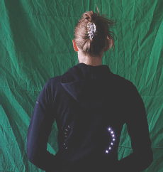
Figure A: The Turn Signal Biking Jacket
This tutorial will show you how to build a jacket with turn signals that will let people know where you’re headed when you’re on your bike. We’ll use conductive thread and sewable electronics so your jacket will be soft, wearable, and washable when you’re done. Enjoy!
A version of this tutorial is also on my website at www.makezine.com/go/turnsignaljacket.
1. Supplies
Get the following (Figure B) from SparkFun Electronics (www.sparkfun.com):
![]() LilyPad Arduino main board, part number DEV-08465
LilyPad Arduino main board, part number DEV-08465
![]() LilyPad USB Link, part number DEV-08604
LilyPad USB Link, part number DEV-08604
![]() Mini USB cable, part number CAB-00598
Mini USB cable, part number CAB-00598
![]() LilyPad power supply, part number DEV-08466
LilyPad power supply, part number DEV-08466
![]() 16 LilyPad LEDs, part number DEV-08735
16 LilyPad LEDs, part number DEV-08735
![]() 2 LilyPad switches, part number DEV-08776
2 LilyPad switches, part number DEV-08776
![]() A spool of 4-ply conductive thread, part number DEV-08549
A spool of 4-ply conductive thread, part number DEV-08549
![]() A digital multimeter with a beeping continuity tester. I use RadioShack’s 42-Range Digital Multimeter with Electric Field Detection (catalog number 22-811).
A digital multimeter with a beeping continuity tester. I use RadioShack’s 42-Range Digital Multimeter with Electric Field Detection (catalog number 22-811).
![]() A garment or a piece of fabric to work on
A garment or a piece of fabric to work on
![]() A needle or two, a fabric marker or piece of chalk, puffy fabric paint, a bottle of fabric glue, and a ruler (available at your local fabric shop or Jo-Ann Stores: www.joann.com)
A needle or two, a fabric marker or piece of chalk, puffy fabric paint, a bottle of fabric glue, and a ruler (available at your local fabric shop or Jo-Ann Stores: www.joann.com)
![]() A pair of scissors
A pair of scissors
![]() Double-sided tape (optional)
Double-sided tape (optional)
![]() A sewing machine (optional)
A sewing machine (optional)
Note: Disclosure: I designed the LilyPad, so I’ll make some $ if you buy one.
2. Design
Plan the aesthetic and electrical layout of your piece: Decide where each component is going to go and figure out how you will sew them together with as few thread crossings as possible. Make a sketch of your design that you can refer to as you work. Figure C shows the sketch for my jacket. Stitching for power (+) is shown in red, ground (-) in black, LEDs in green, and switch inputs in purple.
Important note about the power supply: As you design, plan to keep your power supply and LilyPad main board close to each other. If they are too far apart, you are likely to have problems with your LilyPad resetting or just not working at all.
Why? Conductive thread has non-trivial resistance. (The 4-ply silver-coated thread from SparkFun has about 14Ω/foot.) Depending on what modules you’re using in your construction, your LilyPad can draw up to 50 milliamps (mA) of current, or .05 amps. Ohm’s Law says that the voltage drop across a conductive material—the amount of voltage that you lose as electricity moves through the material—is equal to the resistance of the conductive material times the amount of current that is flowing through it.
For example, if your LilyPad is a foot away from the power supply, the total resistance of the conductive material that attaches your LilyPad to your power supply is about 28Ω. (14Ω in the conductive thread that leads from the power supply’s negative terminal to the LilyPad’s negative petal and 14Ω in the conductive thread that ties the positive terminals together.) So we can expect a drop of 1.4 volts (28Ω * .05 amps). This means that while 5 volts is coming out of the power supply, the LilyPad will only be getting 3.6 volts (5 volts – 1.4 volts). Once the voltage at the LilyPad drops below about 3.3 volts, it will reset. The resistance of the traces from + on the power supply to + on the LilyPad and - on the power supply to - on the LilyPad should be at most 10Ω. Plan the distance accordingly.
If all of this was confusing, don’t worry! Just keep the LilyPad and power supply close to each other in your design.
Transfer the sketch to your garment: Use chalk or some other non-permanent marker to transfer your design to the garment (Figure D). If you want, use a ruler to make sure everything is straight and symmetrical.
Use double-sided tape to temporarily attach LilyPad pieces to your garment. This will give you a good sense of what your final piece will look like. It will also keep everything in place and, as long as the tape sticks, make your sewing easier.
3. Sew your power supply and LilyPad to your jacket
Trim the leads off the back of the power supply: Get out your LilyPad power supply piece and trim the metal parts that are sticking out the back of it. Small clippers like the ones shown in the photo work well, but you can also use scissors (Figure F).
Stabilize your battery on the fabric: Generally, you want to do everything you can to keep the power supply from moving around on the fabric. I recommend gluing or sewing the battery down before starting on the rest of the project. You may also want to glue or sew something underneath the power supply to help prevent it from pulling on the fabric and bouncing around as you move.

Figure B: 1. Conductive thread and needle 2. Chalk for drawing on fabric 3. LilyPad LEDs 4. LilyPad Arduino main board, power supply, and USB link 5. Mini USB cable 6. Fabric glue 7. Switches
If you are working on a thin or stretch piece of fabric—first of all, reconsider this choice! It’s much easier to work on a heavy piece of non-stretchy fabric. If you are determined to forge ahead with a delicate fabric, choose the location for your power supply wisely. It’s the heaviest electronic module, so put it somewhere where it will not distort the fabric too badly. Definitely glue or sew something underneath the power supply.
Sew the power supply’s positive (+) petal to your garment: If you are new to sewing, check out the “How to Sew” Instructable (www.instructables.com/id/How-to-Sew.) before you start for info on how to thread a needle, tie knots, and make stitches. Cut a 3-4 foot length of conductive thread. Thread your needle, pulling enough of the thread through the needle that it will not fall out easily. Tie a knot at the end of the longer length of thread. Do not cut the thread too close to the knot or it will quickly unravel (Figure G).

Figure C: Here’s the design for what you’ll be sewing
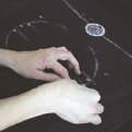
Figure D: Chalk it out

Figure E: Sewing with conductive thread

Figure F: 1. Trim the battery posts off the power supply

Figure G: 1. Sewing on the positive (+) petal of the power supply
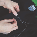
Figure H: Sewing connections
Coming from the back of the fabric to the front, poke the needle into the fabric right next to the + petal on the power supply and then, from the front of the fabric, pull it through. The knot at the end of the thread will keep the thread from pulling out of the fabric. Make a stitch going into the hole in the + petal on the power supply. Do this several more times, looping around from the back of the fabric to the front, going through the + petal each time.
Pay special attention to this stitching. It is the most important connection that you’ll sew in your project. You want to make sure you get excellent contact between the petals on the power supply and your conductive thread. Go through the hole several times (at least 5) with your stitching. Keep sewing until you can’t get your needle through anymore. Do not cut your thread, just proceed to the next step.
Sew from the battery to the LilyPad: Once you’ve sewn the + petal of the battery down, make small neat stitches to the + petal of your LilyPad. I used a jacket with a fleece lining and stitched only through the inner fleece lining so that no stitches were visible on the outside of the jacket.
Sew the + petal of your LilyPad down, finishing the connection: When you reach the LilyPad, sew the + petal down to the fabric with the conductive thread. Just like you were with the battery petal, you want to be extra careful to get a robust connection here. This stitching is making the electrical connection between your power supply and LilyPad.
When you are done with this attachment, sew away from the LilyPad about an inch along your stitching, tie a knot, and cut your thread about an inch away from the knot so that your knot won’t come untied.
Connect the negative (-) petals: Sew the - petal from your battery to the LilyPad’s - petal.
Put fabric glue on each of your knots to keep them from unraveling: Once the glue dries, trim the thread close to each knot (Figure L).
4. Test your stitching
Measure the resistance of your stitching: Get out your multimeter and put it on the resistance measuring setting. Measure from power supply + to LilyPad + and power supply - to LilyPad -. If the resistance of either of these traces is greater than 10Ω, reinforce your stitching with more conductive thread. If you’re not sure how to measure resistance, check out this tutorial: http://tinyurl.com/46eooy (Figure M).
Put a AAA battery into the power supply and flip the power supply switch to the on position. The red light on the power supply should turn on. If it doesn’t and you’re sure you flipped the switch, quickly remove the battery and check for a short between your + and - stitches. (Most likely there is a piece of thread that’s touching both the - and + stitching somewhere.) You can test for a short between + and - by using the continuity tester on your multimeter. See the tutorial at http://tinyurl.com/4l8fvq for information on how to use the continuity tester.
Also check the resistance between the + and - stitching. If the resistance is less than 10KΩ or so, you’ve got a mini-short (probably a fine conductive thread hair that is touching both + and -) that you need to find and correct.
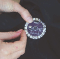
Figure I: Connecting the petals

Figure J: Notice how dense my stitching is here. This is what your stitches should look like.
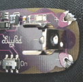
Figure K: Connecting the power supply

Figure L: A glued and trimmed knot. Knots without glue will come unraveled quickly.
If the power supply does turn on, look at your LilyPad. It should blink quickly each time you press its switch. Once these connections are working, turn off the power supply and remove the battery.
Insulate your power and ground stitching: So, your jacket is now full of uninsulated conductive stitches. This is fine when a body is inside of it. A body will prevent sewn traces from contacting each other. But when the jacket is off of a person and you bend or fold it, traces will touch each other and short out. To fix this problem, cover your traces with puffy fabric paint (or another insulator like a satin stitch in regular thread).
Note: you don’t want to cover traces until you’re sure that everything works! So, use good judgment deciding when to coat traces.
5. Sew on your turn signal LEDs
Sew in your left and right signals: Using the same techniques you used to sew the power supply to the LilyPad, attach all of the + petals of the lights for the left turn signal together and to a petal on the LilyPad (petal 9 for me) and all of the + petals for the right signal together and to another LilyPad petal (11 for me). Attach all of the - petals of the lights together and then to either the - petal on the LilyPad or another LilyPad petal (petal 10 for me). Refer back to my design sketches if any of this is confusing (Figures N-Q).
Seal each of your knots with fabric glue to keep them from unraveling. Be careful to avoid shorts; don’t let one sewn trace touch another. In this case, the - traces for the LEDs are all connected, but you want to make sure that the + traces for the left and right signals do not touch the - trace or each other. Here’s my test program:
Test your turn signals: Load a program onto your LilyPad that blinks each turn signal to make sure all of your sewing is correct.
Note: If you don’t know how to program the LilyPad, work through a few of these introductory tutorials before proceeding: www.makezine.com/go/lilypadhome.
Here’s my test program:
// The LED on the LilyPad
int ledPin = 13;
// My left turn signal is
// attached to petal 9
int leftSignal = 9;
// My right turn signal is
// attached to petal 11
int rightSignal = 11;
// the - sides of my signals
// are attached to petal 10
int signalLow = 10;
void setup()
{
// set ledPin to output
pinMode(ledPin, OUTPUT);
// set leftSignal petal to output
pinMode(leftSignal, OUTPUT);
// set rightSignal petal to output
pinMode(rightSignal, OUTPUT);
// set signalLow petal to output
pinMode(signalLow, OUTPUT);
// set signalLow petal to LOW (-)
digitalWrite(signalLow, LOW);
}
void loop() // run over and over
{
delay(1000); // wait 1 sec
// turn the left signal off
digitalWrite(leftSignal, LOW);
delay(1000); // wait 1 sec
// turn the right signal on
digitalWrite(rightSignal, HIGH);
delay(1000); // wait 1 sec
// turn the right signal off
digitalWrite(rightSignal, LOW);
delay(1000); // wait 1 sec
}

Figure M: Measuring resistance

Figure N: Sewing on an LED
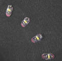
Figure O: Stitching in process, outside view—3 positive petals are sewn together.

Figure P: 1. Negative (-) traces for turn signal LEDs attached to petal 10 2. Positive (+) traces for right turn signal LEDs attached to petal 11
If your layout is the same as mine, you can copy and paste this program into your Arduino window.
If your turn signals don’t work, use your multimeter (and the instructions from the last step) to test for shorts or bad connections and make sure that your program matches your physical layout.
Insulate your turn signal stitches: Cover your traces with puffy fabric paint. Remember, don’t cover your traces until you’re sure everything works!
6. Sew in your control switches
Place your switches: Find a spot for your switches where they’ll be easy to press when you’re riding your bike. I mounted mine on the underside of my wrists. I found a good spot by trying out different places. Check out the photos to see what I mean (Figures R-S).
Once you’ve found a good position, push the legs of the switch through the fabric and bend them over on the inside of the fabric.
Sew in your switches: Sew your switches into the garment. Sew one leg to the switch input petal on the LilyPad and another leg, one that is diagonally across from the first, to ground or another LilyPad petal. I used petal 6 for the switch input on the left side and petal 12 for switch input on the right side. I used - for the - connection on the left side, but petal 4 for the - connection on the right side. Refer back to my design drawing if any of this is confusing (Figures T-X).
When you’re done sewing, go back and reinforce the switch connections with glue. You don’t want your switches to fall out of their stitching.
7. Sew in your indicator LEDs
Sew a single LED onto the sleeve of each arm: These will give you essential feedback about which turn signal is on. They’ll flash to tell you what the back of your jacket is doing, so make sure they’re in a visible spot. Sew the + petals of each LED to a Lily-Pad petal and the - petals of each LED to the - side of the switch (the - trace you sewed in the last step). I used petal 5 for the LED + on the left side and petal 3 for the LED + on the right side. Again, refer back to my design drawings if any of this is confusing.
As always, remember to glue and trim knots and be careful not to create any shorts. Once you sew both wrist LEDs, you’re done with the sewing phase of the project! Now, on to programming…
8. Program your jacket
Decide on the behavior you want: I wanted the left switch to turn on the left turn signal for 15 seconds or so, and the right switch to do the same thing for the right signal. Pressing a switch when the corresponding turn signal is on should turn the signal off. Pressing both switches at the same time should put the jacket into nighttime flashing mode. The wrist-mounted LEDs should provide feedback about the current state of the jacket. Here’s the code I wrote to get that behavior: www.makezine.com/go/lilypadcode.
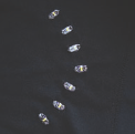
Figure Q: My finished right turn signal. Notice how my stitching doesn’t come through to the outside of the garment.

Figure R: One of the push buttons in action

Figure S: The push button in place

Figure T: Sewing the push button

Figure U: 1. and 2. Stitches from power supply to LilyPad 3. First trace from left switch 4. Left turn signal stitches
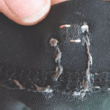
Figure V: The push button sewn in place

Figure W: An indicator LED

Figure X: The circuit from behind
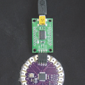
Figure Y: Connecting the USB programmer

Figure Z: The completed jacket
Program your jacket: To program your garment, copy and paste my code into an Arduino window and load it onto the LilyPad. You may have to make some small adjustments first depending on where you attached lights and switches. Play with delays to customize your blinking patterns. Follow my LilyPad introduction instructions at www.makezine.com/go/lilypadhome if you need more information on how to program the LilyPad or how to make sense of my code.
Plug your battery back in and see if it works and… go biking! Take it out for a spin and make sure it all works OK.
Insulate the rest of your traces: Cover the rest of your traces with puffy fabric paint. Again, don’t coat anything until you’re sure it works.
Note: About washing—your creation is washable. Remove the battery and wash the garment by hand with a gentle detergent.
Note: Silver coated threads will corrode over time and their resistance will gradually increase with washing and wear. To limit the effects of corrosion, insulate and protect your traces with puffy fabric paint or some other insulator. You can also revive exposed corroded traces with silver polish. Try this on a non-visible area first to see what it does to your fabric!
Leah Buechley is an assistant professor of media arts and sciences at the Massachusetts Institute of Technology’s Media Lab where she directs the High-Low Tech research michaelsaurus, aka Mike Warren, stays mostly hidden these days caring for his unicorn and eating dragon wings, emerging to see if any spaceships have come close enough to take him away from this planet and into the stars. Until then he creates small wonders, biding his time until he unleashes his next heinous experiment on the world.