
Turn your fridge into a canvas for LED art
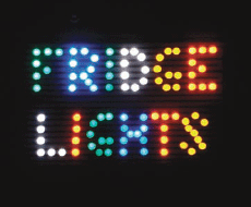
Figure A: Magnetic refrigerator lights in action
With these LED fridge lights, passersby can place the magnetic LEDs any way they wish to create illuminated pictures and messages. It’s great for high traffic kitchens and fun for kids and adults alike.
1. What you need
Most of the materials can be found at local hardware and electronics parts stores or online.
Parts:
![]() Super Shield conductive nickel paint (see Figure B). This can be found at electronics parts stores. It’s usually used to add RF shielding to plastic cases. We will be using it because it’s electrically conductive.
Super Shield conductive nickel paint (see Figure B). This can be found at electronics parts stores. It’s usually used to add RF shielding to plastic cases. We will be using it because it’s electrically conductive.
![]() 1/4” copper tape used for circuit board repair (optional). If conductive paint can’t be found, this may be a possible substitute. It may be a good idea to get some anyway as a way to repair any future scratches or chips in the conductive paint.
1/4” copper tape used for circuit board repair (optional). If conductive paint can’t be found, this may be a possible substitute. It may be a good idea to get some anyway as a way to repair any future scratches or chips in the conductive paint.
![]() Spray Paint. I used Krylon Fusion For Plastic because it sticks to almost anything, doesn’t require a primer, and has a nice finish.
Spray Paint. I used Krylon Fusion For Plastic because it sticks to almost anything, doesn’t require a primer, and has a nice finish.
![]() 10mm LEDs in quantities and colors of your choice. I used 20 LEDs of each—red, green, blue, yellow, and white. These can be bought online from vendors such as www.futurlec.com, www.digikey.com, www.jameco.com, and many others.
10mm LEDs in quantities and colors of your choice. I used 20 LEDs of each—red, green, blue, yellow, and white. These can be bought online from vendors such as www.futurlec.com, www.digikey.com, www.jameco.com, and many others.
![]() 330Ω surface-mount resistors. Get one for each 2.4 volt LED (Typically red, orange, yellow and sometimes green LEDs are 2.4 volts). The 3.6 volt LEDs (typically blue, white, UV, and true green) do not require resistors.
330Ω surface-mount resistors. Get one for each 2.4 volt LED (Typically red, orange, yellow and sometimes green LEDs are 2.4 volts). The 3.6 volt LEDs (typically blue, white, UV, and true green) do not require resistors.
![]() One 4.5 volt, 500 mA AC power supply. By using AC, the polarity of the LEDs won’t matter. They will light up whichever way they are placed onto the grid. This also reduces power consumption because the LEDs will run at a 50 percent duty cycle.
One 4.5 volt, 500 mA AC power supply. By using AC, the polarity of the LEDs won’t matter. They will light up whichever way they are placed onto the grid. This also reduces power consumption because the LEDs will run at a 50 percent duty cycle.
![]() 1/8” diameter x 1/16” NdFeB Nickel plated disc magnets. Get two for each LED. These can be found online from vendors such as http://kjmagnetics.com and http://magnet4less.com.
1/8” diameter x 1/16” NdFeB Nickel plated disc magnets. Get two for each LED. These can be found online from vendors such as http://kjmagnetics.com and http://magnet4less.com.
![]() 1/4” diameter x 1/16” NdFeB Nickel plated disc magnets. I used six—two for attaching the power source to the fridge, and four more for making magnetic jumper wires to bridge the gap between the door and the side of the fridge.
1/4” diameter x 1/16” NdFeB Nickel plated disc magnets. I used six—two for attaching the power source to the fridge, and four more for making magnetic jumper wires to bridge the gap between the door and the side of the fridge.
![]() 5-minute epoxy. Get the kind that you mix from clear and yellow tubes.
5-minute epoxy. Get the kind that you mix from clear and yellow tubes.
![]() Masking tape
Masking tape
![]() 1/4” Quilter’s tape (see Figure C). This is just masking tape but 1/4” wide, the thinnest tape I could find. You can find this in craft stores. Ideally, you want tape that is just slightly wider than the diameter of the magnets used on the LEDs.
1/4” Quilter’s tape (see Figure C). This is just masking tape but 1/4” wide, the thinnest tape I could find. You can find this in craft stores. Ideally, you want tape that is just slightly wider than the diameter of the magnets used on the LEDs.
![]() Solder
Solder
Equipment:
![]() Needle-nose pliers
Needle-nose pliers
![]() Small wire cutters or fingernail clippers
Small wire cutters or fingernail clippers
![]() Soldering iron or gun
Soldering iron or gun
![]() Wire-wrapping tool or other tool with a flat round 1/8” diameter tip. It’s really the 1/8” diameter we’re going to use as a tool, so you could use a grinded down dollar store screwdriver if that’s what’s available.
Wire-wrapping tool or other tool with a flat round 1/8” diameter tip. It’s really the 1/8” diameter we’re going to use as a tool, so you could use a grinded down dollar store screwdriver if that’s what’s available.
![]() X-Acto knife
X-Acto knife
![]() Wooden toothpick
Wooden toothpick
![]() Putty/Clay/Plasticene/Play-Doh; this is for holding LEDs in place while you work on them.
Putty/Clay/Plasticene/Play-Doh; this is for holding LEDs in place while you work on them.
2. Paint the fridge
Wash the surface of the fridge first. Once dry, use masking tape to mark off the borders of the grid (display area) and the power traces going to it (see Figure D). Get some newspaper and with more masking tape, cover up all the areas you do not want to get paint on (Figure E).
Apply one even coat of the base paint. I used this base coat to cover any existing scratches on the surface of the fridge and also to help ensure that the conductive paint will not peel off.
Once the base coat is dry to the touch, start applying the 1/4” Quilter’s tape to form two separate traces that will power the grid, and then apply all the traces in the grid itself. I used a marker to mark out the vertical spacing between the horizontal lines, then followed the dots as I placed the tape by hand.
Note: Just try to get the spacing right at first and not worry about the edges yet. I marked out dots to keep spacing at 10mm intervals.
The grid should basically look like two interlocked combs, as shown in Figure F. One power line will go to the left side and make “teeth” going back to the right, and the other power line will start at the right side, making teeth go to the left. Neither of the two power lines should ever touch at any point. The grid is basically an open circuit and closed only when the magnetic LEDs will be placed upon it—one magnet of the LED touching one power line and the other magnet touching the other.
As soon as the masking tape is applied, start painting with the conductive paint (see Figure G). This stuff requires caution—you want to make sure that the area is well ventilated. Open all windows and doors, and turn on the vent over the stove.
Keep applying more layers until the can is nearly empty. You may want to save a little bit just in case you ever need to touch up the conductive traces. If you are painting a larger surface area, you may consider using more than one can.
3. Remove the masking tape
Once the paint is dry to the touch, start removing the newspapers and masking tape, starting from the outside and working your way inside to the finer traces (see Figure H, I, and J).

Figure B: Krylon Fusion paint and conductive paint
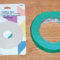
Figure C: Quilter’s tape and masking tape

Figure D: 1. The target area for the LED grid 2. The power line to the grid

Figure E: Add one line of thin masking tape to split the power into two lines
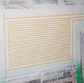
Figure F: The white is where the conductive traces will be and the masking tape is where it won’t be conductive. Make sure the top trace is separate from the bottom trace.

Figure G: Our first coat of conductive paint. Keep adding more coats until the can is empty, or nearly empty if you want to keep a bit “just in case.”
Be very careful pulling up the masking tape because the conductive paint is so thick that it may pull off along with the tape. I used an X-Acto knife to score the edges in the corners of the fine traces to prevent the paint from being lifted off. Should any conductive traces start lifting, you may be able to press them back down if the paint is still not completely dry. After it is dry, you may try using Krazy Glue to glue down any lifted corners.
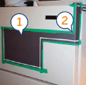
Figure H: 1. Try to have thick and even coverage with the conductive paint 2. Peel off the masking tape going from outside-in

Figure I: The thin masking tape gets tricky to remove, so be careful
4. Hook up the power
I used a 4.5 volt / 500 mA AC power adapter with magnets attached (see Figure K) to both wires to power the grid. The wires are glued to the magnets and the tops (not bottoms) of the magnets are covered in hot glue to prevent the two magnets from shorting the circuit should they touch each other. The magnets can be oriented so that the bottoms are magnetically opposed—which should prevent them from attaching to each other if they get pulled from the fridge.
There is a gap in the circuit between the door and the side panel of the fridge. To complete the circuit, I used two small jumper wires with magnets attached to both ends (see Figure L). Make sure to leave enough slack in the wires to cover the gap even when the fridge door is opened all the way.
Now the grid has power. Since the LEDs are not constructed yet, you may test the circuit by placing some magnets onto the traces of the grid and lying some LEDs over the magnets (see Figure M). The pins/wires on LEDs are attracted to the magnets, so no special effort is required for this test.
I measure 15Ω of resistance on each trace going from the back of the fridge to the grid, and about 15Ω more from the side of the grid to the center. When I place a jumper wire in the center of the grid, I measure about 60Ω between both power terminals at the back of the fridge—a full circuit between the power supply, crossing any given point of the grid and back to the power supply, is about 60Ω.
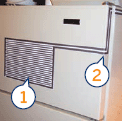
Figure J: 1. Our finished display/LED power grid 2. If you want to hide the power source, you may paint over this part again, just make sure to leave contact points for the power wires and the jump between the door and the side.
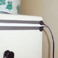
Figure K: The power supply connected to the grid with magnets
I found that the paint’s conductivity increased as the paint dried, so don’t be too worried if you get readings higher than that at first. If they’re much higher or much lower, you may opt to use a different voltage power supply to compensate or use copper tape to reduce resistance in the traces.
5. Assemble the 3.6 volt LEDs (blue, white, and green)
Bend the pins on the LEDs to lie flat, then use the wire-wrapping tool (or similarly tipped tool) as a shape to bend the wires around so that they encircle the tool. Try to make it so the outside of the circle shapes reaches the outside edges of the bottom of the LED and both circles are on opposite sides of the LED. Figure N shows LEDs in various stages of assembly.
Once the wires are bent, use nail clippers or small wire cutters to cut off excess wire. You only need one looping of the wire to form a circle with each LED pin. Next, use needle-nose pliers to adjust the loop so that the inside of the circle is just a little bit smaller than the diameter of the magnets. This will add a bit of spring to the wires so that they clamp over the magnets when you push them in. (Don’t add the magnets just yet.)
Before attaching the magnets to the LEDs I used modeling clay to hold the LEDs upside-down (see Figure O). Get your magnets ready. Mix up a small batch of epoxy. Apply a small bit of epoxy into the center of each circle of wire. Apply just enough for the magnets to hold without having the epoxy over-flow over the bottom of the LED.

Figure L: These magnets/wires jump the gap between the door and the side panel

Figure M: 1. A test to work out that 2.4 volt LEDs could coexist with 3.6 volt LEDs on the same grid 2. I didn’t have the final LEDs at this point, so I just placed magnets and ordinary 5mm LEDs on the grid to test

Figure N: 1. Bend the pins into loops 2. Cut off excess wire and adjust the size of the loops 3. Finished LED. (Also pictured: Leatherman, wire-wrapping tool, magnets)
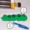
Figure O: 1. Some LEDs after the magnets have been epoxied into the bent wires 2. A pen cap is perfect for pushing magnets into their slots
Now place magnets onto one side of each LED. They will most likely just jump onto the top edge of the circle of wire as the wires will attract the magnets. Once one row is placed, use the cap from a cheap pen to push the magnets into the center of the circle and press down on them until they “click” into place. If they don’t “click,” or are too hard to push into the circle, you may need to adjust the diameter of the looped wire on your next batch of LEDs.
Add magnets to the second row of pins in the same way. If any epoxy gets onto the pen cap, just wipe it clean with a tissue. This will prevent covering the tops of the magnets with epoxy.
For the next minute or two, use the pen cap to level off the tops of the magnets. Then let them sit for 20 minutes or so as shown in Figure P. Do not move the magnets now because it will potentially break its contact with the looped wire.
After 20 minutes, use a toothpick to carefully scrape any epoxy that may have covered the top surface of the magnets. Don’t try placing the magnets onto your fridge until several hours have passed as the metal surface of the fridge will pull at the magnets and break the contact with the LED wires.
You can test your LEDs before the epoxy has completely hardened with a 3V battery attached to small wires—simply touch the wires to the magnets to see the LEDs light up. Try both ways because LEDs will only light up if power is hooked up in the correct polarity.
6. Assemble magnets to the 2.4 volt LEDs (red and yellow)
The 2.4 volt LEDs start similar to the 3.6 volt LEDs, but the wires are bent in a different way to allow for a resistor to be added to the bottom of the LED.
Bend the longer wire of the LED to lie flat and point straight out. Next bend the shorter wire to lie flat around 40 degrees below the first wire. Bend the first wire to come back towards the LED. Make the bend overhang the edge of the LED a bit to make it easier to cut later. Next, use the wire-wrapping tool to curl the bent back wire into a circle. Do the same with the next wire. Try to keep the loops evenly apart, with the edges of the circles going right up to the edges of the LED. Figure Q shows the steps.
Use nail clippers or a wire cutter to cut off excess wire. You only need the wire to make one loop around. Use needle-nose pliers to tighten the inside diameter of the circles to be just slightly smaller than the diameter of the magnets so that the wires will clamp around the magnets when they are pushed into place later.
Place the LEDs in the modeling clay and use epoxy to attach the magnets just like with the 3.6 volt LEDs (see Figure R).
When it comes to testing the LEDs to check that they light up, add an extra resistor to the battery because 2.4 volt LEDs will burn out without a current limiting resistor (see Figure S).
Let the epoxy harden for about two hours, but do not place these LEDs onto your fridge because without the resistor (next step), they will burn out.
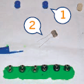
Figure P: 1. Finished LEDs waiting for epoxy to harden completely 2. Small batteries with wires for testing assembled LEDs
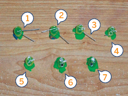
Figure Q: 1. Bend wires flat—long wire straight out, short wire at an angle 2. Bend the long wire back 3. Twist the long wire into a loop 4. Twist the short wire into a loop 5. Clip off excess wire 6. Attach magnets inside wire loops with epoxy 7. After epoxy hardens, clip off bent wire (from 2.) and solder in the resistor

Figure R: The first row of magnets about to go in (epoxy has already been applied, magnets are stacked in the lower left)
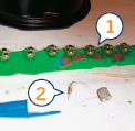
Figure S: 1. Partially assembled 2.4 volt LEDs; the resistors get added after the epoxy hardens. I added a resistor to the batteries once I started assembling the 2.4 volt LEDs.

Figure T: 1. I used the nail clippers to cut the loopedback wire so I could add the resistors 2. 330Ω surface-mount resistors 3. Double sided tape on the tip of the blade makes it easy to pick up and position the resistors
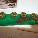
Figure U: Just before soldering. The resistors are in place, clamped under the LED wires.
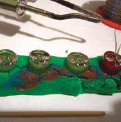
Figure V: After soldering
7. Add resistors to the 2.4 volt LEDs (red and yellow)
Once the epoxy on the 2.4 volt LEDs has hardened, use nail clippers or small wire cutters to cut the overhanging wire loop off the LEDs (see Figure T). Don’t add too much stress to the wires as this might pull off the newly epoxied wire loop and magnet. If this happens you can use Krazy Glue to reattach it.
Cut and bend the wires to make room for a surface mount resistor. The resistor should rest about halfway between the edge of the magnets and the edge of the LED itself. Use an X-Acto blade or toothpick to bend the wires down a bit so that they will clamp down on the resistor once it is wedged underneath them.
Attach a small piece of double-sided tape to the end of your blade. This will make it easy to pick up and position the tiny resistors. Figure U shows the LEDs with the resistors in place.
Note: You can use a toothpick to position the resistors, bend the LED pins into place, and also occasionally to displace accidental solder bridges between the two pins.
Now it’s time to solder in the resistors. This takes a delicate touch. Make sure to clean the soldering iron’s tip often and lightly touch the points you want to solder with both solder and pre-heated soldering iron. If the solder doesn’t “take” the first time, wait until the wires cool and try again. Make sure not to touch the magnets with the soldering iron. The magnets will break down if exposed to excessive heat. If you accidentally solder a bridge over both wires, use the toothpick to push apart the solder as you reheat it.
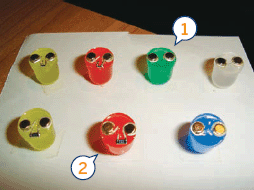
Figure W: 1. I used even smaller surface mount resistors at first before moving onto the larger ones below 2. Examples of the finished LEDs: 2.4 volt LEDs have resistors, and 3.6 volt LEDs don’t.
For those who are unsure of their soldering ability, it might be possible to omit the soldering step altogether, if you make sure the wires firmly clamp down on the resistors. Test the LEDs to make sure they’re working and then put a dab of epoxy over the resistor to keep it from moving out of its current (working) position. After the epoxy hardens a bit, be sure to test the LEDs.
Repeat steps 5, 6, and 7 until all the LEDs are assembled. Figure V shows some assembled 2.4 volt LEDs.
8. The finished project
Figure W shows a variety of assembled LEDs. Gather all the LEDs and place them on the fridge. Now it’s time to start making pictures on your fridge as shown in Figure X.
When not used in the grid, the magnetic LEDs can also be used as regular refrigerator magnets—although they won’t light up unless they’re placed in the grid.
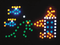
Figure X: An action scene with the magnetic lights
User Notes
John, author of this Instructable, in reply to a question from bitchmobile, Instructables member: 900 [LEDs are] quite a bit more than this project will easily handle. You will have to use copper tape leading up to the grid instead of conductive paint to better handle the current and also stop the dimming that would happen if that many LEDs were put on the grid.
The change to copper tape leading to the grid would reduce the resistance of the electric circuit, so the power supply would also have to change to 3.5 VAC to keep the LEDs from burning out.
Because the LEDs are lighting on AC and not at their full brightness, they won’t actually consume anywhere near 20mA each, but that will still require a hefty power supply… 5 Amps?
John Kowalski is a software engineer who has a passion for electronics, art, photography, and anything retro. Oh, and MacGyver is his hero.