
Blinkybug, Maker Faire Version
Create fuzzy little bugs that blink all day long By Ken Murphy
Blinkybugs (www.blinkybug.com) are small, electro-mechanical insects that respond to stimulus such as movement, vibration, and air currents by blinking their LED eyes. They’re incredibly simple, yet have a certain lifelike quality.
I’d been making variations of these for a while now, and showing others how to make them at museums, fairs, workshops, etc. It wasn’t rocket science, but there was some tricky soldering involved, and they usually took a person at least an hour to put together for the first time. I wanted to come up with a solder-free version for the workshop I was organizing for the Maker Faire (www.makerfaire.com). So after a bit of experimenting, I came up with this simpler, solder-free design shown in Figure A.
Note: Blinkybug Kits, which include all the parts to make four bugs, are now available through MAKE magazine’s Maker Shed at www.makershed.com/ProductDetails.asp?ProductCode=MKKM1
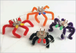
Figure A: The Blinkybug
1. Tools and parts
Tools you will need: (Figure B)
![]() Glue gun + glue sticks
Glue gun + glue sticks
![]() Rotary tool w/metal cutting blade (a hacksaw or similar may work)
Rotary tool w/metal cutting blade (a hacksaw or similar may work)
![]() Safety goggles
Safety goggles
![]() Metal file
Metal file
![]() Measuring tape or yardstick
Measuring tape or yardstick
![]() Wire cutters
Wire cutters
![]() Needle-nose pliers (2 pairs would be nice)
Needle-nose pliers (2 pairs would be nice)
![]() Permanent marker
Permanent marker
![]() Scotch tape
Scotch tape
![]() Scissors
Scissors
Parts: (Figure C)
![]() .009" guitar string
.009" guitar string
![]() Coin-cell battery (3V CR2032)
Coin-cell battery (3V CR2032)
![]() 5mm LEDs (2 per bug)
5mm LEDs (2 per bug)
![]() Pipe cleaners (aka “chenille sticks”)… assorted colors
Pipe cleaners (aka “chenille sticks”)… assorted colors
![]() Thin copper tubing: 1/16 x .014
Thin copper tubing: 1/16 x .014
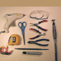
Figure B: The tools
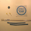
Figure C: The parts
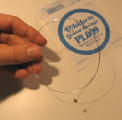
Figure D: Prepare the guitar string
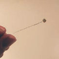
Figure E: Trim this end of the string
I obtained the copper tubing at a hardware store, and it should also be available in hobby shops. 1/16 is the outer diameter in inches, and .014 is the wall thickness. Its inner diameter happens to be about .035", which is important because the guitar string (which is .009") needs to fit through.
LEDs can be found anywhere on the Webernet, and are actually fairly cheap at RadioShack if (and only if) you buy the variety pack. You can obtain the coin-cell batteries at your local drug store, and they are also available widely online, such as at DigiKey. You should be able to get “singles” of the guitar strings at any music shop. The pipe cleaners can be found at tobacco shops and arts & crafts suppliers.
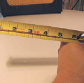
Figure F: Measure the tube
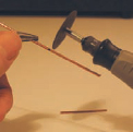
Figure G: Cut the tube
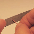
Figure H: File the ends
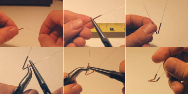
Figure I: Make the antenna guide
2. Preparing the guitar string
The guitar strings I use (D’Addario, shown in Figure D) are 39" long, so you can cut them into three 13" pieces (one bug requires a single 13" length). First, trim the end with the ball and the little extra twisted bit (Figure E), then measure and cut. Put these aside for now.
3. Prepare the copper tubing
The copper tubing is cut into 1-1/2” lengths (1 piece per bug). This will act as the guide for the guitar string/antenna, so the guitar wire must fit through the tube after the pieces are cut. This turns out to be tricky as it’s very easy to block the tube opening when cutting. I find that my Dremel tool does OK most of the time, but on many pieces I end up bunging the thing up. Wire clippers definitely do NOT work, as they unfailingly crimp the ends closed.
Measure and mark the copper tubing at 1-1/2” inch intervals as shown in Figure F. Now carefully cut the copper tubing with your rotary tool (Figure G)… of course while wearing eye protection as little copper bits will be flying every which way! Set it at a high speed, and let the tool do the work… don’t force the tubing against the cutter.
I tried this with a hacksaw with little luck… maybe you’ll do better! For the Faire and kits, I’m getting them pre-cut at the factory to bypass this trouble.
Finally, clean up the cut ends with a metal file (Figure H).
4. Antenna guide
This piece will serve as a stable base that holds the guitar string antennae in their proper position.
Grab a single length of guitar string and a single piece of the cut tubing. Thread the string through the tubing, and pull the tube to the middle-position of the cut guitar string (centered at 6-1/2").
Now, holding things in place so the tube doesn’t slide around, grab the tubing near its center and bend it in half, forming a “V” shape. The angle should be fairly small, around 45 degrees or less. At this point, the guitar string should not be in danger of slipping out of position.
Next, the top third of each arm of the “V” should be bent. If the V is laid flat, the bend should go “upward” about 45 degrees. Figure I shows how to do all this. Two pairs of pliers come in particularly handy here.
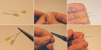
Figure J: Prepare the eyes, part one. The longer LED lead is positive (+, the anode).
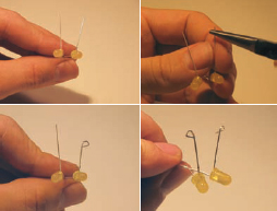
Figure K: Prepare the eyes, part deux
5. Prepare the “eyes,” part one
Grab a couple LEDs of the same color (or not). Take a look and see that one of the wire leads is longer than the other. This is the anode, or the positive (+) side of the LED, and the shorter is the cathode, or negative (-). This is important, as LEDs only work in one direction! If you’re not sure that the wires have never been cut (maybe they were salvaged from another project), then look closely at the LED from below. There will be a flat portion of the round plastic package. The lead nearest this flat bit is the cathode.
Bend the anode at the base of the LED so that it is 90 degrees from the cathode. Repeat for the other LED.
Next, cross the ends of each cathode, grabbing the ends with pliers. Twist it like a twist-tie, giving it three or four turns. The LEDs should remain pointing in more or less the same direction, and the anodes should remain roughly parallel. The two LEDs should now be firmly twisted together. If it seems to have a bit of wiggle, give the twisted part a squeeze with the pliers. Mash it good. Figure J shows all the steps.
6. Prepare the eyes, part deux
Next, create a small loop on the end of each anode. Grab the tip of one anode with the end of the needle-nosed pliers, and give it a turn, rotating it outward until a small loop is formed. Leave a small gap in the loop for now, as the guitar string will need to sneak through.
Repeat the same for the other anode, twisting it in the opposite direction. See Figure K for the details.
7. Assemble antenna, eyes, and body
For this step you will need the eye assembly, the battery, and the antenna assembly. Note that the battery has a “+” side (it’s marked).
Grab a piece of scotch tape, about 2" long. Hold the lower part of the “V” of the antenna assembly against the “+” side of the battery. Lay the tape across the lower part of the “V,” so that equal lengths of tape are extending in either direction. Press the tape firmly on the “+” side so it holds the “V” in place.
Next, hold the twisted leads of the LED assembly along the “bottom” of the battery (opposite from where the antennae are attached). The LEDs should point in the same direction as the arms of the “V,” and the looped anodes should extend “upward” (that is, in the direction of the “+” side of the battery). Tightly wrap the tape around the entire battery, so that everything is held firmly in place.
(Figuring out how to fasten this together without soldering was key in simplifying the process… I definitely took some inspiration from the “LED Throwies” Instructable at (www.instructables.com/id/LED-Throwies) and on page 108 in this book.
At this point, the LEDs may light up if the guitar string makes contact with the LED anodes. For now, gently bend the anodes out of the way. Figure L shows the steps.
8. Give it legs
The pipe cleaner “legs” are going to be attached to the bottom of the battery (where the LEDs are attached) with hot glue. Plug in your glue gun and let it warm up.
Grab some pipe cleaners and cut them into roughly 3" pieces, and arrange them as shown in the second panel of Figure M.
Have the assembled bug body on hand, and drop a blob of glue onto the center point of the legs. As Figure M shows, I’m pretty sloppy, as hot glue is fairly forgiving. But you might want to be careful to not let too much get onto your work surface.
Quickly stick the bug, bottom-first, onto the glue-blob as shown. Give it a minute or so to cool and gently pick it up from the work surface. (Hopefully it won’t be stuck!)
At this point, it’s a good idea to apply a little bit of extra glue to the underside of the legs to make sure they’re solidly attached.
Give the glue a few minutes to cool down and set. Now bend the legs into a buglike pose!
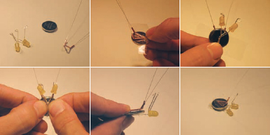
Figure L: Assemble the antenna, eyes, and body
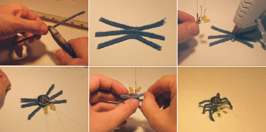
Figure M: Give it some legs
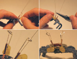
Figure N: Lining everything up; when at rest, the antenna must pass through the loops without touching
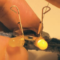
Figure O: When the antenna contacts the loop, the LED turns on
9. Line things up
Almost done: the next step is to get the antenna (guitar string) to pass through the anode loops. The antenna guide (copper tubes) need to be pointing the antennae in roughly the correct direction.
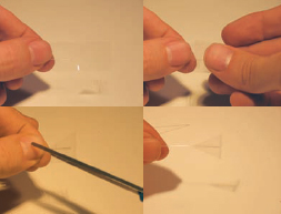
Figure P: Making the antenna flap; even a tiny little flap greatly increases the Blinkybug’s sensitivity to air currents
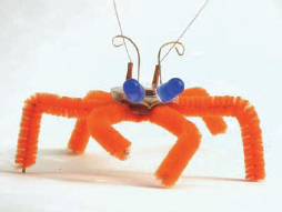
Figure Q: A finished Blinkybug
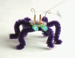
Figure R: Blinkybug with eyes “blinking”
The objective is to get the guitar string to pass through the anode loops so that when the bug is perfectly still, the antennae don’t touch the sides of the loop. However, with any movement or vibration, the antennae will make contact with the loops, close the circuit, and momentarily light up the LEDs.
Using a pair of pliers (or two), try to get everything aligned as described. It helps to grab the entire “loop” and rake it back a bit, so that the guitar wire is perpendicular to the loop. If you left a gap in the loop, you should be able to easily pass the guitar wire in. If not, you may have to pull the loop open a bit with the needle-nosed pliers. Gently squeeze the loop closed once it’s in.
You will also want to get the eyes in a position that you like. This all requires a certain amount of futzing until things get lined up. Figure N shows how to futz things into place, and Figure O shows one of the eyes lit up.
As a final step, you might want to attach little scotch-tape flaps on the end of the wire, which makes them more sensitive to wind, and less likely to poke you in the eye. Figure P shows how to do this.
You now have a working Blinkybug as shown in Figures Q-R. The eyes should be “off” when the bug is sitting undisturbed, but should blink rhythmically when you pick it up, move it, or it catches a breeze. If the eyes seem stuck on, you will need to adjust the position of the loops. If the bug does not seem sensitive enough, you might want to try to make the loops a bit smaller.
Enjoy your bug!
Ken Murphy grew up in Massachusetts but has since migrated to San Francisco, where he works on websites for a public broadcasting company. He divides his free time between running off to the mountains, and toiling in his workshop creating strange objects that blink and bleep. He’s scored music for movies, done a bit of writing, and most recently has been attempting to turn his living room into a camera obscura.