
Simulate the behavior of fireflies with a microcontroller and some surface-mount LEDs By Xander Hudson
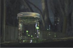
Figure A: The jar of fireflies
This project uses green surface-mount LEDs along with an AVR ATtiny45 microcontroller to simulate the behavior of fireflies in a jar.
1. About this project
The inspiration for this project comes from having never lived in an area where fireflies were common and being deeply fascinated whenever I encountered them in my travels.
The flash patterns have been digitized from firefly behavioral research data found online and were modeled in Mathematica so that variations of speed and intensity could be generated. The final output was transformed by a lightness (www.poynton.com/notes/colour_and_gamma/GammaFAQ.html#lightness) function and written into header files as 8-bit PWM (pulse-width modulated) data.
The software is written in avr-gcc C (GNU C for the Atmel AVR chip) and source code is provided along with a pre-compiled .hex file for convenience. You can download both here: www.makezine.com/go/fireflysrc.
The code has been significantly optimized for efficiency and to minimize power consumption. Crude runtime estimates predict a 600mAh 3V CR2450 battery should last between 4 to 10 months, depending on the song pattern used. The source comes with two patterns, song1 and song2, with song2 as default. Song2’s estimated runtime is 2 months, song1’s is 5 months.
This project involves a fair amount of surfacemount level soldering. However, the circuit design is trivial and the fact that we’re able to use an off-theshelf SMD prototyping board rather than having a custom PCB made greatly saves on cost.
It would be very simple to create a non-surfacemount version using the PDIP version of the ATtiny45 and through-hole LEDs.
The cost of the electronic components comes in at around $10-$15 (after shipping) and assembly time is on the order of two hours.
2. Parts
In this section I list the parts I used in the construction of this project. In many cases, the exact part is not required and a substitute will suffice. For instance, it isn’t required that you use a CR2450 battery to power the circuit, any 3V power supply will suffice and CR2450s just happened to be the cheapest battery that I found that fit the size and capacity requirements I was looking for. Figure B shows many of these parts.
![]() One AVR ATtiny45V microcontroller, 8-pin SOIC package, DigiKey part number ATTINY45V-10SUND (see note A)
One AVR ATtiny45V microcontroller, 8-pin SOIC package, DigiKey part number ATTINY45V-10SUND (see note A)
![]() One Surfboard 9081 SMD prototyping board (www.capitaladvanced.com/9081.htm), DigiKey 9081CA-ND
One Surfboard 9081 SMD prototyping board (www.capitaladvanced.com/9081.htm), DigiKey 9081CA-ND
![]() Green LEDs (6), DigiKey 160-1446-1-ND (see note B)
Green LEDs (6), DigiKey 160-1446-1-ND (see note B)
![]() One 22.0K 1206 resistor (see note C)
One 22.0K 1206 resistor (see note C)
![]() 100Ω 1206 resistors (2) (see note B)
100Ω 1206 resistors (2) (see note B)
![]() One CR2450 battery holder, DigiKey Part# BH2430T-C-ND
One CR2450 battery holder, DigiKey Part# BH2430T-C-ND
![]() One CR2450 battery (any 3V power supply will do) One spool of #38 Magnet wire from http://ngineering.com, part number N5038
One CR2450 battery (any 3V power supply will do) One spool of #38 Magnet wire from http://ngineering.com, part number N5038
![]() Six inches or so of bare thin wire. I used stripped wirewrapping wire but about anything will do.
Six inches or so of bare thin wire. I used stripped wirewrapping wire but about anything will do.
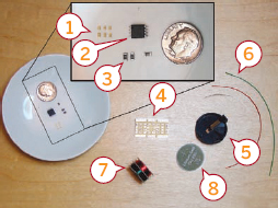
Figure B: 1. Green LEDs (0603 package) 2. Atmel AVR ATtiny45V microcontroller 3. Resistors in 1206 package (2x100Ω, 1x22.0kΩ) 4. Surfboard 9081 SMD prototyping board 5. CR2450 battery holder 6. Bare wire for jumpering pads on SMD board, red and green wires for attaching battery holder 7. #38 Magnet wire 8. CR2450 3V battery
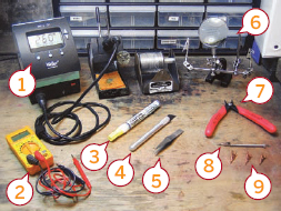
Figure C: 1. Weller soldering station 2. Multimeter for testing the board 3. Water-soluble flux pen 4. X-Acto knife 5. Tweezers 6. Two Helping Hands with magnifier 7. Flush-cut shears 8. “Clip-on-a-stick” 9. Micro clips
Notes:
![]() A. The difference between an ATtiny45V and an ATtiny45 is that the ATtiny45V is spec'd to run on voltages between 1.8V–5.5V while the ATtiny45 wants 2.7V–5.5V. For this project, the only implication is that the ATtiny45V can possibly run for just a little bit longer as the battery dies. In reality this probably isn’t the case and the ATtiny45 can be considered interchangeable with the ATtiny45V (guess which one I happened to have on-hand when I started?). Use whatever one you can get your hands on. Also, the ATtiny85 will work just fine too, just for a little bit more money.
A. The difference between an ATtiny45V and an ATtiny45 is that the ATtiny45V is spec'd to run on voltages between 1.8V–5.5V while the ATtiny45 wants 2.7V–5.5V. For this project, the only implication is that the ATtiny45V can possibly run for just a little bit longer as the battery dies. In reality this probably isn’t the case and the ATtiny45 can be considered interchangeable with the ATtiny45V (guess which one I happened to have on-hand when I started?). Use whatever one you can get your hands on. Also, the ATtiny85 will work just fine too, just for a little bit more money.
![]() B. Substituting a different model of LED with different current-draw characteristics will have implications on what resistor you use. See the Circuit Schematic appendix on the Instructables site (www.instructables.com/id/Jar-of-Fireflies) for more information and be sure to check the spec sheet for your LEDs.
B. Substituting a different model of LED with different current-draw characteristics will have implications on what resistor you use. See the Circuit Schematic appendix on the Instructables site (www.instructables.com/id/Jar-of-Fireflies) for more information and be sure to check the spec sheet for your LEDs.
![]() C. This is only a pull-up resistor, so the specific value is not important. It just needs to be big enough without being too big. See the Circuit Schematic appendix online for more information.
C. This is only a pull-up resistor, so the specific value is not important. It just needs to be big enough without being too big. See the Circuit Schematic appendix online for more information.
3. Tools
These are the tools I used—some are in Figure C
![]() RadioShack #270-373 1-1/8” Micro Smooth Clips (4)
RadioShack #270-373 1-1/8” Micro Smooth Clips (4)
![]() One “clip-on-a-stick”—one of the Micro Smooth Clips mounted on a nail or other sort of stick for manipulating and twisting thin wires
One “clip-on-a-stick”—one of the Micro Smooth Clips mounted on a nail or other sort of stick for manipulating and twisting thin wires
![]() One temperature-regulated soldering iron with a fine tip (I use the Weller WD1001 digital soldering station with 65 watt iron and 0.010" x 0.291"L micro tip). On a budget, however, a 15-watt Radio Shack style soldering iron should be fine. 260˚C is a good temperature to solder LEDs without damaging them.
One temperature-regulated soldering iron with a fine tip (I use the Weller WD1001 digital soldering station with 65 watt iron and 0.010" x 0.291"L micro tip). On a budget, however, a 15-watt Radio Shack style soldering iron should be fine. 260˚C is a good temperature to solder LEDs without damaging them.
![]() One set of helping hands; the third hand was cannibalized from another set
One set of helping hands; the third hand was cannibalized from another set
![]() One multimeter (for circuit testing)
One multimeter (for circuit testing)
![]() One set of Xcelite 170M flush cut wire shears, DigiKey part number 170M-ND
One set of Xcelite 170M flush cut wire shears, DigiKey part number 170M-ND
![]() Some flux. I like the Kester water-soluble flux pen, DigiKey part KE1808-ND. It works like a magic marker and rinses off with warm water.
Some flux. I like the Kester water-soluble flux pen, DigiKey part KE1808-ND. It works like a magic marker and rinses off with warm water.
![]() Some solder (the thinner the better)
Some solder (the thinner the better)
![]() Light tweezers with a fine sharp point (Gingher model G-7600, 3-1/2")
Light tweezers with a fine sharp point (Gingher model G-7600, 3-1/2")
![]() X-Acto knife or razor blade
X-Acto knife or razor blade
![]() An AVR programmer such as the USBtinyISP programmer from Adafruit Industries (see the “Dance Messenger” or “Programmable LED” Instructables in this book for information on AVR programmers)
An AVR programmer such as the USBtinyISP programmer from Adafruit Industries (see the “Dance Messenger” or “Programmable LED” Instructables in this book for information on AVR programmers)
![]() Pomona 5250 8-SOIC test clip (available from HMC Electronics for around $10)
Pomona 5250 8-SOIC test clip (available from HMC Electronics for around $10)
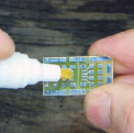
Figure D: Applying the flux
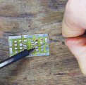
Figure E: Applying solder to the pad
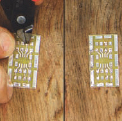
Figure F: Solder the bare wire to a pad, then cut it to length after the solder has cooled
Figure G: Solder the resistor to one pad first, leaving the other pad dry
4. Circuit board assembly—part 1 of 3
Now it’s time to prepare the circuit board and attach the resistors.
Flux the pads (Figure D)
I tend to flux everything, even when using solder that already contains flux. This is especially true when I’m using the water-soluble flux pen since cleanup is so easy and the pen makes it easy to not get flux everywhere. You can scribble over all the pads on the board and once you’re done soldering, simply rinse it off under hot water.
Apply solder to the pads (Figure E)
There are a number of good guides on the Internet with examples of how to solder surface-mount components. In general, you want to start by putting a little bit of solder on one pad as shown.
Solder jumper wire across pads (Figure F)
The consequence of not having a custom PCB made for this project is that we have to add our own bus wires. Note the bus wires on PIN_C, PIN_D, and PIN_E (see Figure H for the pin assignments). These are not strictly necessary but it looks cleaner this way and gives us some elbow room when attaching a clip to the microprocessor for programming.
Solder resistors to the board (Figure G)
Holding the component in a pair of tweezers, heat the solder that you applied to the pad and hold one side of the component in the solder until it flows onto the pin. You want to keep the component flush with the board while you’re doing this. Then, solder the other side. Only add solder to the other pad after the first pad has cooled and is holding the component flush to the board.
5. Circuit board assembly—part 2 of 3
Now it’s time to solder the microcontroller to the board.
Bend the pins on the microcontroller
Another consequence of not having a custom PCB made is that we have to deal with the unusual width of the ATtiny45 chip, which happens to be slightly wider than will comfortably fit on the Surfboard. The simple solution is to bend the pins inwards so that the chip stands on the pads instead of sitting on them (Figure I).
Solder microcontroller to board
Again, there are many SMD soldering guides online but the executive summary is this:
![]() Apply flux to the pins of the chip (I find this makes it much easier to get a good solder joint, especially with the weird surface topology of these bent pins).
Apply flux to the pins of the chip (I find this makes it much easier to get a good solder joint, especially with the weird surface topology of these bent pins).
![]() Hold the chip to the pad and draw solder down from the square pad and onto the first pin of the chip (add more solder if there isn’t enough on the square pad but you’ll typically have enough already).
Hold the chip to the pad and draw solder down from the square pad and onto the first pin of the chip (add more solder if there isn’t enough on the square pad but you’ll typically have enough already).
![]() Make sure that the solder actually flows up and onto the pin. The soldering motion is sort of like “pushing” the solder onto the pin (Figure J).
Make sure that the solder actually flows up and onto the pin. The soldering motion is sort of like “pushing” the solder onto the pin (Figure J).
![]() Once the first pin is soldered, go to the pin on the opposite corner of the chip and solder that down as well. Once those two corners are tacked down, the chip should remain firmly in place and the remaining pins become simple to complete.
Once the first pin is soldered, go to the pin on the opposite corner of the chip and solder that down as well. Once those two corners are tacked down, the chip should remain firmly in place and the remaining pins become simple to complete.
Also, be very careful that you solder the chip to the board in the correct orientation! If you look closely on the chip you’ll see a little round in dentation on the top in one of the corners. That indentation marks pin #1 that I marked as Reset in Figure H. If you solder it down in the wrong orientation, I promise you that it won’t work. :-)
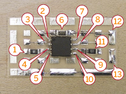
Figure H: 1. 100 Ω resistor 2. Reset 3. PIN_C 4. PIN_A 5. GND 6. 22.0kΩ resistor used as pull-up 7. VCC 8. PIN_D 9. PIN_B 10. PIN_E 11. 100Ω resistor 12. VCC 13. GND (jumper across from here to the chip’s GND)
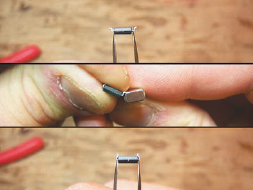
Figure I: Bending the pins to fit the board using a piece of metal (the wirestripper from a wirewrap tool)
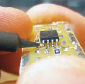
Figure J: Draw the solder from the square pad and push it onto the pin.
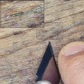
Figure K: Gently scrape away about a millimeter of insulation (don’t damage the wire)
6. Circuit board assembly—part 3 of 3
Now you need to test all the connections.
Since everything is fairly small here, it’s quite easy to make a bad solder joint that looks fine to the eye. That’s why it’s important to test everything. Use a multimeter and test all of the pathways on the board for connectivity. Make sure to test everything; for example, don’t touch the probe to the pad that the pin of the chip looks soldered onto, touch the pin itself. Also test the resistance values of your resistors and make sure they match with their expected values.
A small problem now is easy to correct, but it will become a big headache if you don’t discover it until after all the LED strings have been attached.
7. Making a firefly LED string—part 1 of 4
Now it’s time to prepare the wires.
Ngineering.com has a good writeup (www.ngineering.com/Wire_wiring_tips.htm) of how to work with the magnet wire and covers tinning as well as twisting it which are two key steps of making a firefly LED string. However I’ve never been satisfied with the results of burning away the insulation as they describe in the guide and have instead settled on gently scraping the insulation away with a razor. It’s quite possible that I simply wasn’t doing the tinning steps right (despite many attempts) and your own mileage may vary.
Cut red and green wires to the desired string length. I prefer to use different lengths of wire for each firefly string so that once assembled they don’t all hang at the same “altitude.” Generally I calculated the lengths that I was going to use by figuring out the shortest string (based on measuring the jar I was going to use), the longest string, and dividing the interval between them equally into 6 measurements. The values I ended up with for a standard widemouth jelly jar are: 2-5/8", 3", 3-3/8", 3-3/4", 4-1/8", 4-5/8".
Strip one end of each wire exposing a millimeter or less. Using the razor method, gently scrape the insulation away by softly dragging the blade over the wire (Figure K). Turn the wire and repeat until the insulation has been removed. Using this method I find it hard to only strip a millimeter of wire so I simply trim the length of the exposed wire to one millimeter after I strip it.
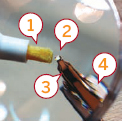
Figure L: 1. Flux pen 2. LED 3. Microclip 4. Helping hands

Figure M: Surface-mount LED polarity
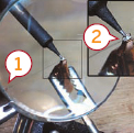
Figure N: 1. The green wire is being held in place by another microclip (out of view) held by one of the helping hands. Don’t try to hold the wire in place with your fingers 2. The LED gently resting on the pad
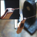
Figure O: The wires, soldered to the LED
8. Making a firefly LED string—part 2 of 4
Next, you need to prepare the LED.
Using a microclip, pick up an LED so that the bottom side is facing out, exposing the pads. Mount the microclip and LED in the helping hands and apply flux to the pads on the LED as shown in Figure L.
9. Making a firefly LED string—part 3 of 4
Here’s where you’ll solder the LED.
Using another microclip, pick up the green wire first and mount it in the helping hands.
Now comes the hardest part of the project, soldering the LED. Manipulate the helping hands so that the exposed part of the green wire is resting gently on the cathode pad of the LED (Figure M shows the orientation; the—side is the cathode). This is the time-consuming part that requires patience and cannot be rushed. Plan your moves in advance and act slowly and with deliberation. This is basically ship-in-a-bottle type delicate work and shouldn’t be underestimated. However you don’t have to be the favorite son of a watchmaker in order to pull this off either, it is within the realm of mortals. I find it considerably easier to manipulate the arms of the helping hands rather than the wire itself or the microclip.
Rest the exposed part of the wire on the cathode pad and arrange your magnifying gear and lighting to make sure you can perfectly see what you’re doing in preparation for soldering.
Using a soldering iron set to around 260˚C, pick up a very small blob of molten solder onto the tip of the iron and, very gently, touch the tip of the iron to the cathode pad on the LED as shown in Figure N. A small amount of solder should instantly run off of the tip and onto the pad (thanks to the flux), securing the wire to the pad in the process. Be careful not to burn the LED by holding the iron to the pad too long (3 seconds max, when done right you need less than 0.10 seconds of tip contact, it’s very fast).
Unfortunately what tends to happen here is that you knock the wire off the pad with the tip of the iron, forcing you to go through setting it all up again. For that reason you have to be very slow and gentle with the iron. I tend to place my elbows on the workbench on either side of the helping hands and hold the iron with both hands in a seppuku (en.wikipedia. org/wiki/Seppuku) type grip, gently bringing the iron down towards the pad. This grip is sometimes the only way I can get enough control. Another tip: don’t drink a pot of coffee before attempting this.
This does get easier with practice.
Very gently tug on the green wire to test that it’s firmly secured. Release the wire (not the LED) from the microclip and, without changing the orientation of the LED, repeat the process with the red wire, only this time soldering it to the anode (+) pad of the LED. Since the red wire will be flying over the cathode (green) pad, it’s important to not have too much exposed red wire, lest it come down in contact with the cathode pad and create a short. Figure O shows an LED with green and red wires attached.
10. Making a firefly LED string—part 4 of 4
Next, twist the wires and test the LED.
Once both wires have been attached to the LED, it’s time to twist the wires. Twisting the wires results in a cleaner look, greatly adds durability to the LED string, and also reduces the number of delicate freeflying wires you have to deal with when working with the board later.
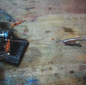
Figure P: Twisting a pair of wires
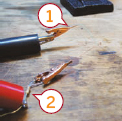
Figure Q: 1. Using microclips to get a more reliable connection to the little wires 2. 100Ω resistor
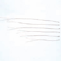
Figure R: An hour or two of your life that you’ll never get back
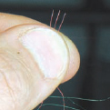
Figure S: Grab three red wires between thumb and forefinger. Clip them together using a microclip and mount the microclip on your helping hands
To twist the wires, begin by mounting a microclip in your helping hands and clip it to the two wires right beneath the LED. Now, using another microclip (I have it mounted on a nail to make this process easier), grab the other end of the string about 1.5" from the end (you’ll leave that length untwisted). Gently twist the microclip while applying just enough tension to keep the wires straight until the wires are sufficiently twisted together. I tend to prefer a somewhat tight twist as this results in a string that’s easier to keep straight (Figure P).
Once the string has been twisted, strip about 2-3mm from the free end of the wires and test by putting 3 volts through a 100Ω resistor and into the ends of the wires. I’ve found it very difficult to make a good connection by pressing probes into the bare ends of the magnet wire so I clip microclips onto the ends and touch those with the probes instead (Figure Q). You don’t have to get a good solid “on” from the LED for the string to pass the test, since even with the clips it’s hard to get a good connection. Even a few flickers are enough to pass. When soldered, the connection will be much better.
Set the LED string aside in a safe place. Repeat this process for each of the six strings. Figure R shows six strings in a variety of lengths.
Note: Figure Q shows a 100Ω resistor being used to protect the delicate LED. LEDs are a hair-trigger when it comes to voltage sensitivity and it’s possible to burn them out by driving them just a few tenths of a volt higher than their rated specification unless you use a resistor to protect them. This is doubly true for SMD LEDs since they’re so small.
11. Attaching LED strings to the board—part 1 of 2
Once you’ve completed all six of the LED strings and the circuit board, it’s time to attach the strings to the board.
Sort the LED strings into two groups of three. For each group, we will twist and solder the three red wires together into one and then solder that to the board.
Grab three of the red wires between your thumb and forefinger as shown in Figure S. After taking special care to ensure that the stripped ends of the three wires all line up, microclip the three wires close together and mount the microclip in the helping hands.
Twist the exposed parts of the wires together as shown in Figure T. This is to prevent them from coming apart while you solder them to the board.
Tin the twisted ends of the wires with solder. Use flux first to ensure a good contact between the wire tips (the last thing you want to do is have to untwist these three wires to get at one that’s not making good contact) (Figure U).
Carefully solder the red-wire bundle to the far side pad of PIN_A (Figure V), so that the resistor separates the bundle and the microcontroller. Repeat the process with red wires from the other three LED strings, soldering the bundle to the far side of the resistor on PIN_B. You should now have both 3-string red wire bundles soldered to the board with the green wires flying free.
12. Attaching LED strings to the board—part 2 of 2
Using a similar process to how you made the red 3-wire bundles, join the green wires together into 2-wire bundles and solder them to PIN_C, PIN_D, and PIN_E (Figure W). By not soldering the bundles to the pad closest to the microcontroller, we give ourselves more elbow room should we need to do any touchup soldering work on the microcontroller or attach a programming clip to the board.
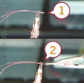
Figure T: 1. Clip right behind the start of the exposed wire 2. Twist to ensure wires don’t come apart
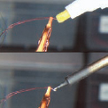
Figure U: Fluxing and soldering
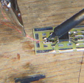
Figure V: Solder the redwire bundle to the pad on the far side of the resistor
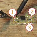
Figure W: 1, 2, and 3: Solder green 2-wire bundles to these pads
Once all the LED strings have been soldered to the board, it’s a good idea to test them as shown in Figure X. With a 3V power source, test the strings by placing a positive voltage on either PIN_A or PIN_B, being careful to place it behind the resistor since 3V will damage these LEDs without it, and moving the negative voltage between PIN_C, PIN_D, and PIN_E. Each combination of pins should result in an LED lighting up when probed.
Note: If your chip happens to be already programmed at this point then simply applying power to the board (VCC and GND) should be enough to test all six LEDs in one go. The provided program cycles through all the LED’s on boot.
13. Preparing and attaching the battery holder
Take the wires that you’re going to use to attach the battery holder with and cut them to length. I tend to use the following lengths:
![]() Red Wire: 2"
Red Wire: 2"
![]() Green Wire: 2-3/8"
Green Wire: 2-3/8"
Strip a little bit off both ends of the wires and solder one end of the wire to the battery holder and the other end to the circuit board, being careful to get the polarities correct as shown in Figures Y and Z.
Also, once you have soldered the wires to the battery holder, you may want to snip the pins on it short so it’s not quite as awkward to attach to the lid of the jar.
14. Final assembly
By this point you’ve completely assembled the circuit board and attached the LED strings and battery holder.
All that’s left is to program the chip and affix the board assembly to the lid of your jar (Figure ZA).
As to how to program the chip, I’m afraid that’s a bit beyond the scope of this document and is heavily dependent on what platform (FreeBSD, Mac OS X, Linux, Windows, etc.) of computer you’re using and what development environment you’re working with. I’ve provided the source code (written for GCC) as well as compiled binaries but figuring out what to do with them is up to you.
Note: The “Dance Messenger” or “Programmable LED” Instructables elsewhere in this book discuss how to program this family of chips, but you will need to use a special clip, described next, to physically connect the chip to the programmer.
Thankfully, there are loads of good resources out there for getting started with AVR programming—here are a couple:
![]() AVRFreaks (www.avrfreaks.net)—This is the ultimate site for AVR. The active forums are indispensable.
AVRFreaks (www.avrfreaks.net)—This is the ultimate site for AVR. The active forums are indispensable.
![]() AVR Wiki (www.avrwiki.com)—I found this site quite helpful when I got started.
AVR Wiki (www.avrwiki.com)—I found this site quite helpful when I got started.
The file firefly.tgz contains the source code and compiled .hex file for this project. You can download this file from www.makezine.com/go/fireflysrc.
This project was built using avr-gcc 4.1.1 (from the FreeBSD ports tree) along with avr-binutils 2.17 and avr-libc-1.4.5. For instructions on setting up avr-gcc on Windows, Mac OS X, and Linux, see the “Dance Messenger” or “Programmable LED” Instructables elsewhere in this book.
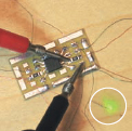
Figure X: Be sure to test from behind the resistor so you don’t damage your LED
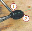
Figure Y: 1. Negative terminal 2. Positive terminal
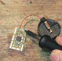
Figure Z: Connecting the positive and negative terminals to the board
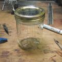
Figure ZA: The assembled jar
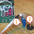
Figure ZB: 1. The Pomona 5250 8-SOIC test clip 2. Make sure the two battery contacts aren’t touching when you program the chip, or it will short out
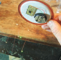
Figure ZC: Inside the lid of the Jar of Fireflies
The Pomona 5250 8-SOIC test clip, shown in Figure ZB, is the only test clip I’ve used which works well with the 8-SOIC AVR processors like the one in this Instructable. Other clips tend to have a problem due to the fact that the AVR chips are a little wider than normal and the other clips weren’t designed for that.
As for attaching the board and battery to the lid, there are probably a million ways to do this but I’m not confident that I’ve found the best one yet. The methods that I’ve tried have been to use either epoxy or hot glue. I’ve already had a few instances of epoxied boards pop off so I wouldn’t recommend using that. Hot glue seems to work ok but I have little faith that after a few hot/cold cycles it’ll fare much better than the epoxy. Figure ZC shows the board attached to the lid.
So, I leave figuring out how to attach the board and battery holder to the lid up to you as well. However I will offer a couple tips:
![]() Be careful when you attach the battery holder that the two pins don’t short out due to the metallic lid. Some lids are insulated, and others aren’t.
Be careful when you attach the battery holder that the two pins don’t short out due to the metallic lid. Some lids are insulated, and others aren’t.
![]() This to That (www.thistothat.com) is a website that offers glue recommendations based on what you’re trying to glue. For glass to metal (the closest approximation I can think of for a silicon circuit board) they recommend “Locktite Impruv” or “J-B Weld.” I haven’t ever used either.
This to That (www.thistothat.com) is a website that offers glue recommendations based on what you’re trying to glue. For glass to metal (the closest approximation I can think of for a silicon circuit board) they recommend “Locktite Impruv” or “J-B Weld.” I haven’t ever used either.
User Notes
In the Comments to this project, Instructables member ccarlson presented a problem he ran into while trying to reprogram a chip that was already in a working circuit. The problem was encountered while using Ladyada’s USBtiny-ISP to program the ATtiny45V for this project. Ladyada herself offered the solution: don’t let the programmer (in this case the USBtinyISP) power the process via USB power, remove the jumper and use a battery to power the circuit instead.
Note: Be sure to check out the web page for this Instructable at www.instructables.com/id/Jar-of-Fireflies for four appendixes, including descriptions of the circuit schematic and possible areas for improvement.
Xander Hudson runs Synoptic Labs in Sacramento, California, and maintains the Synoptic Labs weblog (www.synopticlabs.com).