
CHAPTER 32
Painting in the Viewport Canvas and Rendering Surface Maps
Max is a 3D tool, and creating scenes with Max is quite a bit different from the traditional painting programs. Sometimes when you're working on a scene, especially when applying textures, you'll ache to return to those simple, older painting programs of yesteryear. Happily, Max includes a mode that lets you simply throw paint around just like those old paint programs.
This paint mode is called the Viewport Canvas, and it turns the entire active viewport into a 2D surface; even better, when you are finished painting, your masterpiece is automatically transferred to the current object as a texture map.
If the ability to paint directly in the viewport doesn't interest you, then you'll be happy to know that you can use Max to render out a surface map that you can load into Photoshop or your favorite image-editing package and use as a template for your textures.
Using the Viewport Canvas
The Viewport Canvas lets you easily apply a painted texture to the selected object. It also has a feature that lets you choose the type of brush you paint with. The Canvas also includes a standard paint brush that is configurable and a Clone brush for copying anything viewed in the active viewport, along with several other brushes.
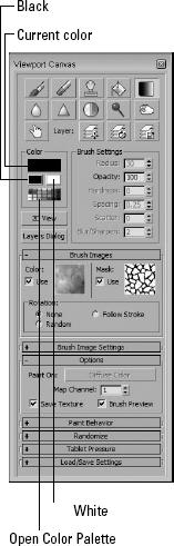
To activate the Viewport Canvas, simply select the Tools ![]() Viewport Canvas menu command, and the Viewport Canvas panel appears, as shown in Figure 32.1.
Viewport Canvas menu command, and the Viewport Canvas panel appears, as shown in Figure 32.1.
The Viewport Canvas palette can be docked to the left or right side of the interface by right-clicking the palette's title bar and selecting the dock location from the pop-up menu.
FIGURE 32.1 The Viewport Canvas panel turns the viewport into a 2D painting canvas.
Setting up an object for painting
The Canvas requires some setup before you can use it. The Viewport Canvas can be used on any object that has mapping coordinates. Mapping coordinates are applied to a primitive object by enabling the Generate Mapping Coordinates option in the Command Panel, or by adding the UVW Mapping or UVW Unwrap modifier to an object.
With an object selected, select one of the brushes in the Canvas palette; if the object has a material with a bitmap applied, you can begin painting right away. If the object doesn't have a material or a texture applied, then the Assign Material dialog box appears, as shown in Figure 32.2.
FIGURE 32.2 The Assign Material dialog box lets you choose the channel to paint on.
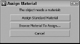
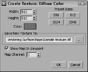
The Assign Standard Material button pops up a list of available channels where the texture may be applied using the Standard material. The Browse Material to Assign button opens the Material/Map Browser, where you can choose the type of material to use. The list of available channels includes Ambient Color, Diffuse Color, Specular Color, Specular Level, Glossiness, Self-Illumination, Opacity, Filter Color, Bump, Reflection, Refraction, and Displacement. After choosing a texture channel, the Create Texture dialog box appears, as shown in Figure 32.3, where you can set the size of the texture map and specify where the texture is saved, or you can select an existing texture. If a new texture is created, you need to specify a path and name for the new texture file. The texture is automatically mapped to the selected channel for the object's material. The Color setting is used for the texture's initial background color.
FIGURE 32.3 The Create Texture dialog box automates the process of applying a material with a texture.
Using the Canvas brushes
After the texture is set up, you can begin painting by clicking the Paint brush icon and dragging in the viewport over the selected object. Using the settings under the brush icons, you can set the Color, Radius, Opacity, Hardness, Spacing, Scatter, and Blur/Sharpen values. The available settings change depending on the brush selected.
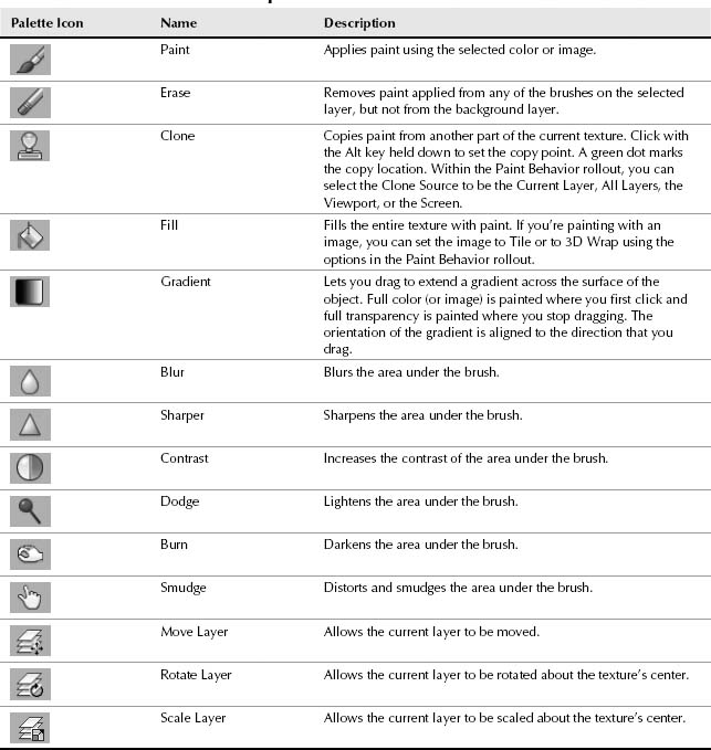
When a brush is selected, it is highlighted in the Viewport Canvas palette and remains active until another brush is selected or until you right-click in the viewport. Table 32.1 lists the available brushes and layer tools.
TABLE 32.1 Viewport Canvas Brush Icons
New Feature
The ability to clone texture from anywhere on the screen in new to 3ds Max 2012.
If the Paint brush is selected, you can immediately switch to the Erase brush by holding down the Shift key. Holding down the Ctrl key lets you click to select a different color from the current texture. Pressing the Spacebar causes a straight line to be drawn from the last painted location to the current cursor location. The Spacebar shortcut also works with the Eraser brush.
With any of the standard brushes, you can hold down the Ctrl+Shift keys to drag and change the brush radius. The Alt+Shift keys change the brush Opacity, and the Ctrl+Alt keys change the brush's Hardness value.
Clicking the Color swatch opens a Color Selector dialog box where you can choose a new color. You also can load a custom color palette using the Open Color Palette button or quickly switch between black and white colors, which is helpful for painting value maps.
At any time while painting, you are free in the viewport to rotate the model around to paint in a different location.
If you don't like the results after the painted texture has been applied to the object, click the Undo/Redo button to remove the last set of changes. Clicking the Undo/Redo button again reapplies the recent changes.
Painting with images
In the Brush Images rollout are two swatches for selecting an image and a mask to paint with. Clicking the swatches opens a palette of presets, as shown in Figure 32.4. Clicking the Browse Custom Maps Directory button opens Windows Explorer to the Viewport Canvas folder where Max is installed. Within this folder are all the custom images and masks that are included in the palette.
FIGURE 32.4 Custom images and masks can be added to the available presets in the Viewport Canvas.
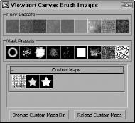
Placing a new image or an image with an alpha channel (for masks) in this folder makes them appear in the presets palette and allows you to select and paint with them. The Reload Custom Maps button reloads any images placed in the folder so they can be seen.
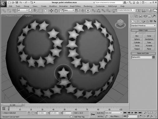
To use an image or a mask, simply enable the Use option next to each. You also have several Rotation options including None, Random, and Follow Stroke. Figure 32.5 shows examples of each painting with stars. The left eye shows the None option, and all stars are oriented exactly the same. The right eye shows the Random option with each star oriented differently; the lower line shows the Follow Stroke option with the stars aligned in the direction of the brush stroke.
FIGURE 32.5 The image rotation options determine how the stars are oriented.
Within the Brush Image Settings rollout are some options for setting how the image is projected onto the object. The options include Hit Normal and From Screen. The Hit Normal option applies the image as if projected down onto the normal of the object. The From Screen option applies the texture as if projected from the screen position onto the object. Other options make the image fit within the brush size and offer tiling options of None, Tile, and Across Screen.
Using paint layers
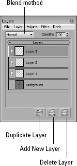
The Viewport Canvas palette lets you paint on layers just like you can in Photoshop. To access the layers, click the Layers Dialog button in the Viewport Canvas dialog box. The Layers palette, shown in Figure 32.6, shows the current layers in a stack. Each layer can be named, and the layers are placed on the object with the top layers appearing on top of the lower layers. You also can select a blend method and an Opacity value. The buttons at the bottom of the Layers palette let you create new layers, duplicate the current layer, or delete a layer. The small light bulb icon to the left of the layer name lets you turn a layer on or off.
When a layer other than the Background layer is selected, you can use the Layer tool icons located at the top of the Viewport Canvas palette. These Layer tools let you move, rotate, and/or scale the current layer.
FIGURE 32.6 The Layers palette lets you work with layers for the current texture.
Caution
Be aware that you cannot erase any paint applied to the Background layer using the Erase tool.
The Layers palette includes some menus that have many of the same commands found in Photoshop. For example, you can use the Layer menu to add layer masks, merge a layer down, flip a layer either horizontally or vertically, or flatten all visible layers.
The Adjust menu includes options for changing the Brightness, Contrast, Hue, Saturation, Levels, or Color Balance. You also have an Auto Levels option. The Filter menu includes filters for blurring, sharpening, finding edges, median, threshold, high pass, and distort.
Within the File menu are options for pasting from the clipboard, loading a bitmap into the current layer, saving the current bitmap (as a flattened file), or saving the image with all layers to a PSD file that can be reopened in Photoshop.
Tip
If you want to maintain the various layers after you're finished painting, be sure to save your texture using an image format that supports layers, such as PSD.
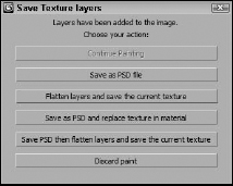
If you've added any layers to your texture and you exit the Canvas, the Save Texture Layers dialog box, shown in Figure 32.7, opens. Using this dialog box, you can choose to continue painting, save the file as a PSD file, which maintains the various layers, flatten all layers and save the texture, save and replace, save, flatten and then save again, or simply discard. If you plan to revisit the layers of your texture, save it as a PSD file, but if you're happy with the results, you can flatten and save the texture.
FIGURE 32.7 The Save Texture Layers dialog box lets you maintain the various texture layers.
Painting in 2D
Painting directly on a 3D object has its advantages, but when painting over a random surface, the results can be irregular. The Viewport Canvas dialog box includes a 2D painting mode that displays the current texture in a rectangular window and lets you paint directly on the texture. This is helpful for textures that need to be projected onto an object such as those with text.
To access the 2D painting mode, simply click the 2D View button under the colors and the current texture is opened in a window, as shown in Figure 32.8. The buttons at the top of this window let you see the UV wireframes, fit the texture in the view, or view the image at its actual size. Any changes made to the texture in 2D painting mode are immediately reflected on the selected object in the viewports.
Clicking the 2D View button again toggles the 2D painting mode off, and the 2D Paint window closes.
Using the paint options
When the Viewport Canvas palette is open, several additional rollouts hold the options that affect the various brushes and texture. Within the Options rollout, you can select which map type and channel to paint on. There is also an option to Save Texture. If this option is disabled, any paint applied to the texture isn't saved. This lets you try a different look without saving it. You can also do this by painting on a new layer that could be deleted. The Brush Preview option shows the outline and size of the brush as you paint.
Within the Paint Behavior rollout are options to have the paint affect any areas of the object within the brush's spherical radius or to apply the paint through the entire object with the Depth option. The Mirroring options let you mirror all paint strokes across the X, Y, or Z axes.
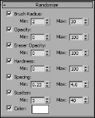
The Randomize rollout, shown in Figure 32.9, lets you set the minimum and maximum values for several different settings including Brush Radius, Opacity, Spacing, Scatter, and Color.
Using the Table Pressure rollout, you can select which attributes are affected by an increase in the tablet pressure. The options include Brush Radius, Opacity, Hardness, and Scatter.
The Load/Save Settings rollout includes buttons for saving and loading the Viewpoint Canvas settings. Settings are saved using a simple text file. There is also a button for saving the current settings as the default.
FIGURE 32.8 2D painting mode lets you paint directly on the texture without any perspective distortion.
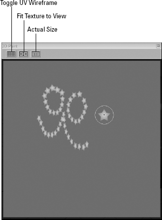
FIGURE 32.9 Using the Randomize rollout, you can add variety to the texture.
Tutorial: Face painting
To show off the Viewport Canvas, we do some face painting on a women's head model. This model was created by Zygote Media and is a good example of a high-res model.
To paint on a character's face using the Viewport Canvas, follow these steps:
- Open the Face painting.max file from the Chap 32 directory on the CD.
This file includes a women's head mesh created by Zygote Media.
- Rotate the head model so the cheek is clearly visible, apply the UVW Map modifier to make sure the object has mapping coordinates with the Planar map, and click the View Align button.
- Open the Viewport Canvas panel with the Tools
 Viewport Canvas menu command.
 - Select the model, and click the Paint Brush icon in the Viewport Canvas panel, then select the Diffuse Color option in the pop-up menu. In the Create Texture dialog box that pops up next, select the 512 × 512 preset and click the file button next to the Save New Texture field to open the file dialog box. Save the file as Face Painting texture.tif, and click the Ok button.
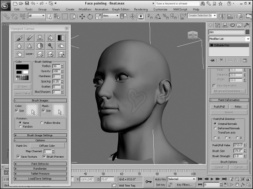
- Set the brush Radius to 32, the blending mode to Normal, and the Opacity to 100, and choose a bright red color. Then click the Brush icon, and draw a heart on the women's cheek. Then click the Paint icon again to apply the texture to the model.
Figure 32.10 shows the resulting applied texture.
FIGURE 32.10 The Viewport Canvas painting mode can be used to apply paint directly to a model.
Using Vertex Colors
Another similar feature to the Viewport Canvas is the Vertex Paint modifier. This modifier lets you apply colors to a model without the weight of a texture. When creating models for games, the size of the texture map can be prohibitive. I mean, what model that weighs in at 16KB or less wants to carry around a 2MB texture map? The solution that much of the gaming world relies on is to apply a single color to a vertex. Having each vertex remember its color (or even several colors) requires very little additional information for the mesh and can create some good shading. Colors are then interpolated across the face of the polygon between two different colors on adjacent vertices.
The results aren't as clean and detailed as texture maps, but for their size, vertex colors are worth the price.
Assigning vertex colors
Vertex colors can be assigned in the Surface Properties rollout for Editable Mesh and Editable Patch objects, and in the Vertex and Polygon Properties rollouts for Editable Poly objects. They also can be assigned in Face, Polygon, and Element subobject modes using a little rollout section called Edit Vertex Colors. Within this section are two color swatches for selecting Color and Illumination values. The Alpha value sets the alpha transparency value for the vertex.
Painting vertices with the Vertex Paint modifier
Another, more interactive way to color vertices is with the Vertex Paint modifier. This modifier lets you paint on an object by specifying a color for each vertex. If adjacent vertices have different colors assigned, a gradient is created across the face. The benefit of this coloring option is that it is very efficient and requires almost no memory.
The Vertex Paint modifier lets you specify a color and paint directly on the surface of an object by painting the vertices. The color is applied with a paintbrush-shaped cursor. The modifier can be applied multiple times to an object, giving you the ability to blend several layers of vertex paints together. You can find this modifier in the Modifiers ![]() Mesh Editing submenu.
Mesh Editing submenu.
Note
After the Vertex Paint modifier has been applied to an object, the Paintbox automatically reappears whenever the object is reselected.
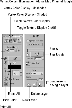
Applying this modifier opens a Vertex Paint dialog box called the Paintbox, shown in Figure 32.11. At the top of the Paintbox are four icons that can be used to show the visible results of the painting in the viewports. The options include Vertex Color Display–Unshaded, Vertex Color Display–Shaded, Disable Vertex Color Display, and Toggle Texture Display On/Off.
The Vertex Color icon flyout lets you work on the Vertex Color, Illumination, Alpha, or any one of the 99 available map channels. The lock icon locks the display to the selected channel, or you could be looking at a different channel from the one you are painting.
The large Paint and Erase buttons let you add or remove vertex colors using the color specified in the color swatch. You also can select colors from objects in the viewports using the eyedropper tool and then set the Opacity.
FIGURE 32.11 The Paintbox palette for the Vertex Paint modifier includes a wealth of features.
The Size value determines the size of the brush used to paint. Max supports pressure-sensitive devices such as a graphics tablet, and you can set the brush options using the Brush Options dialog box. When painting on the surface of an object, a blue normal line appears. This line guides you as you paint so you know you're on the correct surface.
Cross-Reference
The Painter Options dialog box also is used by the Skin modifier and the Paint Deformation tool. It is described in detail in Chapter 13, “Modeling with Polygons.”
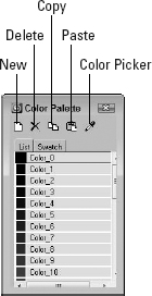
Beneath the Brush Options button is a Palette button that opens the Color Palette interface, shown in Figure 32.12. The Color Palette holds custom colors and lets you copy and paste colors between the different swatches. Collections of colors can be saved by right-clicking the Color Palette and selecting the Save As command. Color palettes are saved as Color Clipboard files with the .ccb extension.
FIGURE 32.12 The Color Palette can display colors as a list or as swatches.
The Paintbox also includes three subobject selection icons. These icons can be used to select certain Vertices, Faces, or Elements to be painted. This limits the painting to the selected subobjects only. You also can select to Ignore Backfacing and use Soft Selection.
The Blur brush button lets you blur colors across polygons using a brush that works just like the Paint and Erase brushes.
The Adjust Color dialog box lets you change all the painted colors applied to an object using HSV or RGB color sliders. The Preview option makes the color adjustment visible in the viewports if selected. Below the Adjust Color icon is the Blur Selected icon that blurs together all the vertex colors based on the designated Amount value.
Colors can be mixed between layers using the various blending modes. Clicking the New Layer button adds a new instance of the Vertex Paint modifier to the Modifier Stack; the Delete Layer button does the opposite. Click the Condense to a Single Layer button to merge all the consecutive Vertex Paint modifiers to a single instance using the selected blending mode.
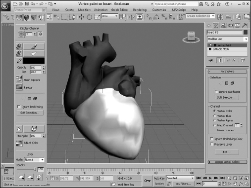
Tutorial: Marking heart tension
As an example of using the Vertex Paint modifier, imagine a doctor who has a 3D model of the human heart. While discussing the results of the latest test with a patient, the doctor can color parts of the heart model to illustrate the various points.
To color on a human heart using the Vertex Paint modifier, follow these steps:
- Open the Vertex paint on the heart.max file from the Chap 32 directory on the CD.
This file includes a heart mesh created by Viewpoint Datalabs.
- Select a portion of the heart model, and choose Modifiers Mesh Editing Vertex Paint to apply the Vertex Paint modifier.
- In the Paintbox that opens, choose the Vertex Color Display–Shaded button at the top of the Vertex Paint dialog box, select the red color, and click the Paint button. Then drag the mouse over the surface of the Perspective view.
Figure 32.13 shows the resulting color.
FIGURE 32.13 The Vertex Paint modifier can apply color to an object by assigning a color to its vertices.
The Assign Vertex Color utility
The Assign Vertex Color utility works a little differently. It converts any existing material colors to vertex colors. To use this utility, select the utility from the Utilities list that opens when you click the More button in the Utility panel, select an object, choose a Channel, choose a Light Model (Lighting + Diffuse, Lighting Only, or Diffuse Only), and click the Assign to Selected button.
Rendering Surface Maps
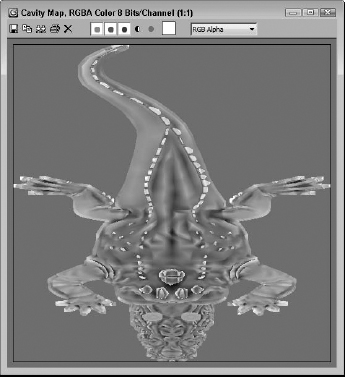
Max can be used to create some useful maps based on the geometry of the object. For example, a Cavity map is generated by looking at the concavity of the model. This appears as a grayscale map where the convex portions are white and the concave portions are black. Such a map can then be reused as a diffuse dirt submaterial map for showing those areas that are tight and indented. These tightly concave areas are the likely areas for non-specular highlights and for dirt to appear on old and weathered models.
Max can use the Render Surface Map feature to render several types of surface maps, including the following:
- Cavity map: The Cavity map creates a grayscale map that highlights convex areas in white and concave areas in black. The Contrast value defines the difference between black and white values.
- Density map: The Density map option creates a map that shows the areas where the vertices are closest together as white and farther apart as black.
- Dust map: The Dust map option creates a grayscale map that identifies the areas that face upward as white and the underneath areas as black, as if the dust were to settle from above and land on all the white areas.
- SubSurface map: The SubSurface map is used to identify those areas of the mesh that are thickest as black and the thinnest areas of the mesh as white. This map type is used to show how likely light would pass through a given area. The Blur value is used to blur those areas between black and white.
- Selection to Bitmap: This map is used to identify a specific subobject selection. Each selected vertex is displayed as a white dot.
- Texture Wrap: The Texture Wrap feature lets you load in a texture that is wrapped about the object in a way to eliminate all seams. This texture could be a simple skin or hide texture. The Tile value is the number of times the texture is repeated end to end to cover the surface.
- Bitmap Select: This feature allows you to select specific subobject selections based on the color of the applied bitmap. For example, if you load a bitmap with white lines running through it, all polygon faces that touch those lines are selected.
To access the Render Surface Map panel, shown in Figure 32.14, select the Rendering ![]() Render Surface Map. This feature works only on Editable Poly objects that have mapping coordinates. If any of these conditions are missing, a warning dialog box appears when you click one of the mapping buttons.
Render Surface Map. This feature works only on Editable Poly objects that have mapping coordinates. If any of these conditions are missing, a warning dialog box appears when you click one of the mapping buttons.
FIGURE 32.14 The Render Surface Map panel can create several different types of maps.
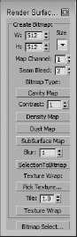
The Width and Height values set the resolution of the rendered bitmap. The Size button has several presets. You also can set the Map Channel and the Seam Bleed values. When you click the map type, the map is generated and displayed in the Rendered Frame Window. Figure 32.15 shows the Cavity map for the crocodile model. The jagged fins are all white because they stick out.
FIGURE 32.15 The Cavity map shows areas that are convex and concave.
Summary
This chapter covered a couple of key features for applying materials. The Viewport Canvas lets you paint directly in the viewport and have the results transferred to the selected object. Surface maps can be rendered to provide a map that gives information about the surface of the object.
In this chapter, you learned about the following:
- Painting on objects with the Viewport Canvas
- Using Vertex Colors to paint models
- Rendering a variety of surface maps
In the next chapter, you learn how the Unwrap UVW modifier can be used to customize the mapping coordinates for an object. You also explore one specific type of mapping a little closer. The Pelt mapping method lets you split and unwrap complicated models by using seams.