
CHAPTER 34
Creating Baked Textures and Normal Maps
3D games pose an interesting dilemma—creating interactive scenes that are displayed in real time with the highest quality graphics. To achieve this, game developers use a number of tricks designed to speed up the rendering time. One of these tricks is pre-rendering textures that include all the lighting information and applying these pre-rendered textures as texture maps. This allows advanced lighting solutions such as global illumination to be included within a game without requiring extra time to render such a complex solution. The process of applying prerendered textures as maps is called baking a texture.
Rendering textures is a significant part of the rendering process, and baking a texture doesn't remove this step; it simply completes the step beforehand, so that the game engine doesn't need to do the texture calculations.
Another common efficiency trick is to use normal maps. Normal maps calculate the lighting results used to light small details that stick out from the surface of an object. These details are then re-created using a normal map that is applied back onto a simplified version of the object. The normal map allows these details to be simulated without the extra polygons used to create them. By allowing simple base objects to have details such as bolts and rivets without the extra polygons, the objects can be redrawn quickly without losing their visual quality.
This chapter covers some of the features found in Max that enable the amazing graphics that are found in the latest real-time games.
Using Channels
When 3D models are used in games, the color and material data for the models is stored in channels. The game engine then knows that if it wants to change the color of a group of vertices because of an explosion that has happened, it just looks in the preset channel, finds the vertices it needs, changes the color, and then goes on with the game.
Working with channels is a very efficient way to interface with the gaming engine, but a sloppy game developer can introduce a model to the game engine with all sorts of unneeded or exaggerated channels. If this happens, the game engine can ignore the extra channels and get the wrong information, which can cause your hero to march off into battle without a weapon. Worse, it can crash the system.
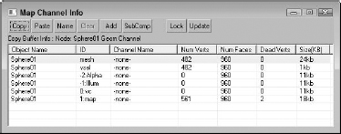
To prevent problems and to streamline the number of channels that are included with game models, Max includes a Map Channel Info editor that you can use to manipulate the various channel data. This editor, shown in Figure 34.1, can be opened using the Tools ![]() Channel Info menu command.
Channel Info menu command.
FIGURE 34.1 The Map Channel Info dialog box lets you edit channel data.
Using the Map Channel Info dialog box
The Map Channel Info dialog box shows lots of information, including the Object Name; its ID; its Channel Name; the number of Vertices, Faces, and Dead Vertices (unattached vertices); and its Size. With this information, you can quickly determine which channels are taking up the most space and eliminate them.
All objects include some default channels for mesh, which holds the geometry; vsel, which holds the selected vertices; −2:Alpha, which holds the alpha channel information; −1:Illum, which holds illumination values; and channel 0:vc, which holds vertex color information. Objects also include at least one default map channel (even if it is empty). These channels cannot be deleted.
Cross-Reference
Vertex colors are covered along with painting on objects in Chapter 18, “Creating Compound Materials and Using Material Modifiers.”
The interface lets you Copy and Paste selected channels. You can give each channel a name with the Name button. Beneath the Copy button, text appears that lists the information currently copied in the Copy Buffer. Selected channels can be copied only between channels that have the same number of vertices.
The Clear button clears out the selected channels, but you cannot clear a map channel if there is another map channel above it. The Add button adds a new map channel to the object. Objects can hold as many as 99 map channels. The Clear and Add buttons also apply UVW Mapping Clear or UVW Mapping Add modifiers to the Modifier Stack. The Paste command also adds a modifier. These modifiers are convenient because they can easily be removed or reordered in the Stack. If changes have been made in the Modifier Stack, the Update button reflects these changes in the Map Channel Info dialog box.
The SubComp button shows the channel components if they exist. For example, map channels can be broken into X, Y, and Z components, and other channels such as Alpha have R, G, and B components. The Lock button holds the current channels even if another object is selected.
Select by Channel modifier
After new channels have been created, you can recall them at any time using the Select by Channel modifier. This modifier is found in the Modifiers ![]() Selection
Selection ![]() Select by Channel menu command. Using this modifier, you can choose to Replace, Add, or Subtract a given channel from the selection. The available channels for the selection are listed by their channel name in a drop-down list.
Select by Channel menu command. Using this modifier, you can choose to Replace, Add, or Subtract a given channel from the selection. The available channels for the selection are listed by their channel name in a drop-down list.
Rendering to a Texture
When working with a game engine, game designers are always looking for ways to increase the speed and detail of objects in the game. One common way to speed game calculations is to pre-render the textures used in a game and then to save these textures as texture maps. The texture map takes more memory to save but can greatly speed the rendering time required by the game engine. This process of pre-rendering a texture is called texture baking.
Caution
If you bake a texture into an object and then render it with the rest of the scene, the object gets a double dose of light.
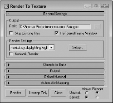
Texture baking can be accomplished in Max using the Rendering ![]() Render to Texture menu command (or by pressing the 0 key). This opens the Render to Texture dialog box. In several ways, the Render to Texture dialog box, shown in Figure 34.2, resembles the Render Scene dialog box, including a Render button at the bottom edge of the interface.
Render to Texture menu command (or by pressing the 0 key). This opens the Render to Texture dialog box. In several ways, the Render to Texture dialog box, shown in Figure 34.2, resembles the Render Scene dialog box, including a Render button at the bottom edge of the interface.
FIGURE 34.2 The General Settings rollout of the Render to Textures panel includes settings for all objects.
To create a baked texture, select a Texture Element from the Output rollout and click the Render button. Clicking the Render button creates the baked texture for the selected object and saves it in the directory specified in the General Settings rollout. It also applies an Automatic Flatten UVs modifier to the Modifier Stack and applies a Shell material to the object. The Shell material contains the object's original material along with the new baked material. You can select which material is displayed in the viewport and which is rendered using the options to the bottom right of the Render to Texture dialog box.
Note
You also can select Use an Existing Channel for mapping coordinates. This is a good choice because the Auto Unwrap option doesn't have the control over the UV coordinates that you may want, and sometimes it does a poor job of unwrapping the mesh.
The interface also includes an Unwrap Only button. This button can be used to flatten the UVW Coordinates for the selected objects and to automatically create a map channel.
General Settings
The General Settings rollout includes an output path where the baked texture is saved. The file is saved by default using the Targa file format. The Skip Existing Files option renders only those elements that don't already exist in the designated directory. The Rendered Frame Window option displays the resulting map in the Rendered Frame Window along with saving the image as a file. For the render pass, you can select which rendering settings to use, including the mental ray rendering engine. The Setup button opens the Render Scene panel, where you can change the render settings.
Selecting objects to bake
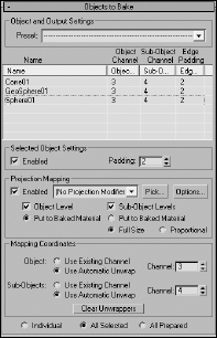
In the Objects to Bake rollout, shown in Figure 34.3, a list displays exactly which objects, subobjects, and channels will be included in the rendered texture. The Padding value defines the overlap in pixels of the texture. The Objects to Bake rollout also includes a Presets list that lets you save and reload defined settings.
FIGURE 34.3 The Objects to Bake rollout of the Render to Textures panel lets you specify which objects are baked into the texture map.
The Projection Mapping section lets you enable the creation of a normal map using a Projection modifier. These settings are covered in detail in the “Creating Normal Maps” section that appears later in this chapter.
The Mapping Coordinates section lets you choose to use the mapping coordinates of the Object or the Subobject selection contained within a specified channel, or you can select to use the Use Automatic Unwrap feature, which automatically flattens the mapping coordinates. If the Use Automatic Unwrap option is selected, you can set the mapping options in the Automatic Mapping rollout. By default, unwrap mapping uses channel 3, but you can change this channel if you wish. If a different mapping uses channel 3 and you don't change this, the new mapping replaces the old one. The Clear Unwrappers button removes any existing Unwrap UVW modifiers from the object's stack.
You can select to bake an Individual object, All Selected objects, or All Prepared objects, which are all objects with at least one texture element.
Output settings
The Output rollout, shown in Figure 34.4, lists the texture elements that are included in the texture map. The Enable option can be used to disable the selected texture element, or elements can be deleted with the Delete button.
FIGURE 34.4 The Output rollout of the Render to Textures panel lets you choose which texture elements are baked.
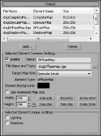
Clicking the Add button lets you select the type of texture elements that you can render. You'll want to use different maps depending on the purpose of the map, and you may want to render several at a time. The available types are CompleteMap, SpecularMap, DiffuseMap, ShadowsMap, LightingMap, NormalsMap, BlendMap, AlphaMap, and HeightMap. You can also change the map size or use the Automatic Map Size option, which bases the map size on the object size. Some map elements present a list of components to include in the map. These components appear below the size settings.
If the mental ray renderer is selected, then Ambient Occlusion is added to the list of available texture elements. The Ambient Occlusion option creates a map that re-creates effects created by limited light bounces resulting from surrounding objects.
Baked Material and Automatic Mapping settings
The Baked Material and Automatic Mapping rollouts, shown in Figure 34.5, provide a way to keep the existing object material using the Shell material. The Clear Shell Materials button removes the Shell materials for the baked objects and restores their original materials.
FIGURE 34.5 The final two rollouts of the Render to Textures panel include settings for handling the baked material and how the texture is mapped.
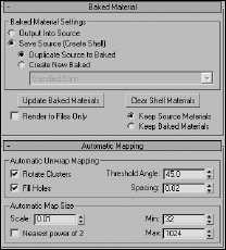
In the Automatic Mapping rollout, you can set how the mapping is applied. If the Use Automatic Unwrap option in the Objects to Bake rollout is enabled, then the object to be baked has the Automatic Flatten UVs modifier applied. For this type, you can set the Threshold Angle (which is the difference between the normals of adjacent faces; if the angular value is greater than the Threshold Angle value, then a hard edge is created between the faces), the Spacing (which is the amount of space between different map pieces), and whether map pieces can be rotated and used to fill in holes of larger map pieces.
The size of the texture map depends on the size of the object, but you can set a Scale value for greater resolution and set Min and Max values to keep the maps within reason. By default, maps are saved to the /images directory, but you can select a different directory if you prefer. The Nearest Power of 2 option causes the map to be optimized for use in memory to a square pixel size that is a power of 2, such as 8×8, 16×16, 32×32, or 64×64.
Note
Most game engines require square texture maps because they are efficiently loaded into memory. Main characters can use texture maps that are 1024×1024 or even 2048×2048, but background characters and props usually only have textures maps that are 256×256 or 512×512, so clustering is important to get as much into the textures as you can.
Tutorial: Baking the textures for a dog model
To practice baking textures, you'll bake a complete map of just the dog's head.
To bake a dog's head texture, follow these steps:
- Open the Doberman.max file from the Chap 34 directory on the CD.
This file includes a dog model created by Viewpoint Datalabs.
- Select Rendering
 Render to Texture (or press the 0 key) to open the Render to Textures dialog box.
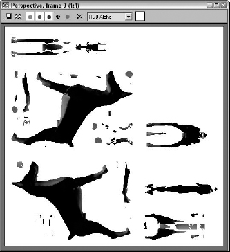
 - Select the dog's body object. In the Render to Textures dialog box, set the Threshold Angle to 75 in the Automatic Mapping rollout, and make sure that the Rendered Frame Window option in the General Settings rollout is set. In the Output rollout, click the Add button and double-click the CompleteMap option. Set the Map Size to 512, select the Diffuse Color option as the Target Map Slot, and click the Render button.
Figure 34.6 shows the resulting texture map. If you look in the Modify panel, you'll see that the Automatic Flatten UVs modifier has been applied to the object. If you look at the material applied to the object, you'll see that it consists of a Shell material.
FIGURE 34.6 A texture map created with the Render to Textures panel
Creating Normal Maps
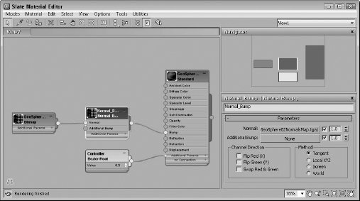
Normal maps are becoming more common in games because they offer a way to increase the bump details of a model by mapping high-detail bump information onto a low-resolution model. Normal maps are created using the Render to Texture interface and applied to an object using the Normal Bump map type found in the Material Editor.
The Normal Bump map type is typically applied as a bump map in the Maps rollout and includes a separate button, shown in Figure 34.7, to apply an additional bump map.
Caution
Normal maps can be displayed in the viewports only if the DirectX display driver is selected.
FIGURE 34.7 Although normal maps are created using the Render to Texture dialog box, they are applied using the Material Editor.
Using the Projection modifier
The Projection modifier is used to create a normal map. It works by being applied to a low-resolution object, and then you pick a high-resolution object that is similar to the low-resolution one. The Projection modifier surrounds the object with a cage that can be manipulated to include all the object details. The Projection modifier is applied using the Modifiers ![]() UV Coordinates
UV Coordinates ![]() Projection command.
Projection command.
Within the Modifier Stack, the Projection modifier includes three subobject modes: Cage, Face, and Element. The Geometry Selection rollout includes a list of objects, a Pick button, and a Pick List for selecting the high-resolution object to be used.
The Cage rollout includes settings for displaying and pushing the cage out from the surface of the object. A Tolerance setting is used for wrapping the cage about the surface. The Selection Check rollout informs you if the Material IDs or Geometry faces are overlapping.
Setting Projection Mapping options
With a Projection modifier applied to a selected object, the Projection Mapping option can be enabled in the Objects to Bake rollout of the Render to Texture dialog box. The object can actually include several Projection modifiers, so a drop-down list lets you select the one to use, or you can use the Pick button to select a target object in the viewports.
The Options button in the Render to Texture dialog box opens the Projection Options dialog box, shown in Figure 34.8. Using this dialog box, you can set the projection method, determine how to resolve how vertices get projected, and define the Map Space.
FIGURE 34.8 The Projection Options dialog box lets you specify how the projection values are determined.
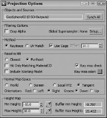
At the top of the Projection Options dialog box is the Source object. The Synch All button causes each object to use its active source for the projection. The two projection methods are Raytrace, which traces each normal line from its source to its target, and UV Match, which works by matching the UV coordinates between the source and the target objects.
For transparent objects, two projection rays may hit the same point. The Resolve Hit options let you set which one is selected, either the Closest or the Furthest. Most projections use the Tangent Map Space, but you can select to use the World, Screen, or Local Map Spaces also.
Note
Before the Projection modifier is applied, you need to have the high-res object and the low-res object positioned at the same place.
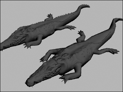
Tutorial: Creating a normal map for an optimized gator
For this example, we reuse the optimized gator created earlier when mesh modifiers were covered. The ProOptimizer modifier was used to reduce this high-res gator model from 34,000 faces to fewer than 1,000. This kind of reduction represents a huge step down for the quality of the model, but it enables it to be lightning fast when used in a game. The normal map makes it possible to use the lower poly model while recovering much of the display quality.
To create a normal map for the optimized gator model, follow these steps:
- Open the ProOptimized gator.max file from the Chap 34 directory on the CD.
- Select and move the low-res gator model over the top of the high-res gator model in the Top viewport.
- With the low-res gator model selected, choose the Rendering Render to Texture menu command (or press the 0 key) to open the Render to Texture dialog box. In the General Settings rollout, select the Scanline renderer, no advanced lighting option as the Render Settings. In the Select Preset Categories dialog box that appears, click the Load button.
- In the Objects to Bake rollout, click the Pick button, select the gator1 object (the high-res gator model) in the Select Targets dialog box that appears, and click the Add button. Then enable Projection Mapping.
- In the Output rollout, click on the Add button and select the Normals map. From the Target Map Slot drop-down list, select the Bump option. Click the 512 button to set the map size, and enable the Output into Normal Bump option.
- Click the Render button at the bottom of the Render to Texture dialog box.
- Drag the low-res gator model away from the high-res model.
- To see the normal map when rendered, open the Material Editor and use the Material Get All Scene Materials menu. This loads all the material nodes including the normal map. There are separate materials for the skin, eyes, and claws. Locate and select the green material node. The normal map is connected to this material's Bump map. Locate the Bump map in the Maps rollout of the Parameter Editor rollout and increase the Bump Amount to 100, and then drag the green material's output socket and drop it on the low-res gator's skin.
- Render the two gators side by side.
Figure 34.9 shows the resulting normal map rendered on the right gator.
FIGURE 34.9 The normal map for the gator can be applied as a bump map to reclaim the high-res details.
Summary
If you're working with games, then you'll want to use these features to help keep your models small and fleet. This chapter covers the following topics:
- Discovering what channels the models have
- Learning how to bake textures
- Creating normal maps using the Projection modifier
The next part takes up the topic of animation again, starting with animation modifiers.