
CHAPTER 39
Animating Characters with CAT
Learning the basics of creating characters
Creating and editing a CAT preset rig
Creating a custom CAT rig
Animating using CAT
Working with muscles
Max has always had a great way to create and animate characters, but in early versions of Max, it was available only as a separate plug-in known as Character Studio. Happily, Character Studio has been integrated into Max to the point that it isn't distinguishable as a separate package. Character Studio was a good first step, and it still exists in Max, but it has lots of shortcomings that make it difficult to work with.
Another plug-in package known as Character Animation Toolkit, or CAT for short, has been embraced by many Max animators, and now CAT is embedded within 3ds Max. CAT offers a simple interface that gets great results whether you're building your own custom rig or animating an existing preset rig.
Although Max includes other features for rigging characters, if you plan on animating a character, then CAT is definitely the way to go. It's an incredible time-saver.
Character Creation Workflow
A typical workflow for creating characters in Max involves first creating a skin mesh object. After the skin mesh is complete, you can create a skeletal rig to drive its animation. The skeleton consists of a pre-rigged set of bones that provide an underlying structure to the character. Animating these bones provides an easy way to give life to the character.
With a skeletal rig created, position the rig within the skin mesh and match the bone links to the relative size and position inside the skin mesh. The bones do not need to be completely within the skin mesh, but the closer they are to the skin mesh, the more accurate the movements of the character are.
After the rig is sized and matched to the skin mesh, use the Skin modifier to attach the skin mesh to the rig. This automatically sets all the envelopes that govern which skin parts move with which bones. You can also use the Skin modifier settings to deform the skin at certain bone angles, such as bulging a muscle when the arm is raised.
Note
The original Character Studio package used the Physique modifier to bind the mesh skin to the biped. Although this modifier still exists and can be used, the Skin modifier includes many new features and is the preferred method for binding a mesh skin to the biped.
The next step is to animate the rig using its animation tools, which can include walk, run, and jump cycles using keys. Along the way, you can save, load, and reuse animation sequences, including motion capture files. Animated sequences can be combined and mixed together to form a smooth-flowing animation using the Motion Mixer.
Creating a CAT Rig
Creating a hierarchical skeleton that is used to control the animation of the mesh skin that is draped over it is quite easy using CAT. The skeleton can be set to be invisible in the final render and exists only to make the process of animating easier. Although Max includes a robust set of tools that can be used to create a skeleton of bones, CAT features automate this entire process and even include a number of prebuilt skeletons.
Cross-Reference
For some characters, modifying a prebuilt skeleton is more work than building a custom skeleton. For these occasions, you can manually create a skeleton structure. Building a rig system by hand is covered in Chapter 38, “Understanding Rigging, Kinematics, and Working with Bones.”
Using prebuilt CAT rigs
To add a prebuilt CAT rig to the scene, simply open the Create panel and select the Helpers category. When you choose the CAT Objects subcategory, you have three options: CAT Parent, CAT Muscle, and Muscle Strand. Click the CAT Parent button and drag in the viewport to place the CAT Parent object. This parent is simply an icon used to control the global position of the rig and is not rendered.
Tip
It is best to place the CAT Parent object at the origin of the scene.
While the CAT Parent object is selected, you can choose a preset rig from the list in the CAT Rig Load Save rollout in the Modify panel or you can select a preset before creating a CAT parent to make the specified preset. The size of the rig is determined by how far you drag in the viewport, or you can set the size using the CATUnits Ratio value in the Command Panel. These custom rigs include a variety of human-shaped and animal-shaped rigs, such as the Alien rig shown in Figure 39.1.
FIGURE 39.1 CAT includes several default preset rigs such as this alien character.
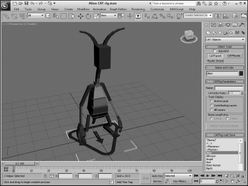
One key advantage of CAT rigs over the rigs available in Character Studio and Biped is that they aren't limited in their structure. Although the available CAT rig presets includes a Base Human and even a Bip01 rig that are used for animating human characters, some of the other presets are dragon, horse, lizard, spider, and centipede. These different rigs have multiple legs, arms, and wings and all are easily controlled.
Modifying prebuilt CAT rigs
With a prebuilt rig added to the scene, you can use the Transform tools to select and move the bones to match the skin mesh. The arms are automatically set up as a Forward Kinematics (FK) chain, so rotating the upper arm bone automatically rotates the rest of the arm bones with it. The legs are set up with an Inverse Kinematics (IK) chain, so you can position the legs by dragging the feet, and the rest of the leg bones follow. By default, all CAT prebuilt rigs have stretchy bones, so if you select and move a bone, the selected and attached bones stretch to maintain the joint connection.
Tip
If you double-click a bone, the bone and all its children are selected. For example, double-clicking a collar bone selects the entire arm, making it easy to move the whole arm into place.
A CAT rig keeps track of the different types of body parts and presents the appropriate set of parameters depending on which bone is selected. For example, if you select any part of the arm, the Limb Setup rollouts appear in the Modify panel. This rollout has specific parameters for the arms and legs, as shown in Figure 39.2. CAT also recognizes spines, tails, palms, digits (fingers and toes), hubs (head and pelvis), and generic bones.
FIGURE 39.2 The Limb Setup rollout appears when any arm bone is selected.
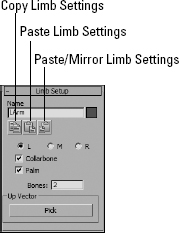
Using these settings, you can specify whether the selected arm is the left, middle, or right arm. You also can choose whether this arm has a collarbone or a palm. The Bones value determines the number of bones that make up the arm. The default is 2, but you can change this to be any whole number from 1 to 20. Because arms can be above or below the head, the Up Vector lets you determine which bone points up.
Beneath the Name are three icons used to copy the settings between two bones. The Copy and Paste Settings buttons let you transfer the settings and orientation of one bone to another. The Paste/Mirror Settings mirror the position of one bone to the opposite side. This lets you set up one arm just right and then quickly copy the settings to the opposite arm.
For spines, you can set the number of bones in the chain, the length and size of the spine bones, and the spine curvature using a simple graph. Tails have these same parameters, plus a height and taper value. For palms and ankles, you can specify the length, width, height, and number of digits.
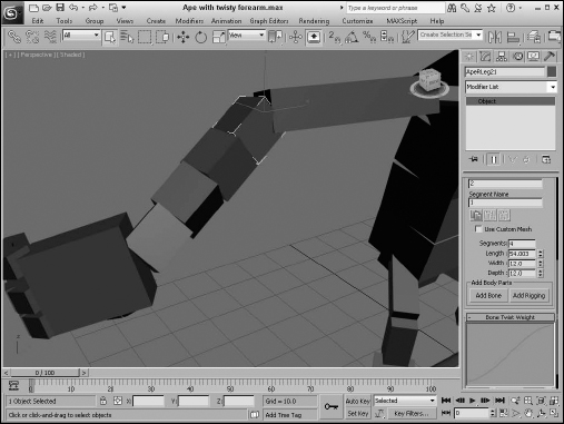
Individual bones that make up the arms and legs also have a Segments value that you can set. Within the Limb Setup is a value for setting the number of bones in the limb, but you can use the Segments value to set the number of segments for each individual bone. This allows you to change a long bone, like the thigh bone, into a series of segments that can rotate independent of each other. This allows for twisting bones, as shown for the forearm in Figure 39.3. You also can set the weight curve for bones with many segments.
FIGURE 39.3 Increasing the number of bone segments allows the bone to twist like this forearm.
If you want to save the preset rig after you've made some changes, simply select the CAT Parent object and click the Save Preset Rig button in the CAT Rig Load Save rollout. Rigs are saved by default to the CATRigs folder using the .rg3 extension. Once saved, the rigs appear in the list with the other CAT rig presets for easy recall.
Rigs also are easy to delete. Simply select the CAT Parent object and press the Delete key.
Using custom meshes
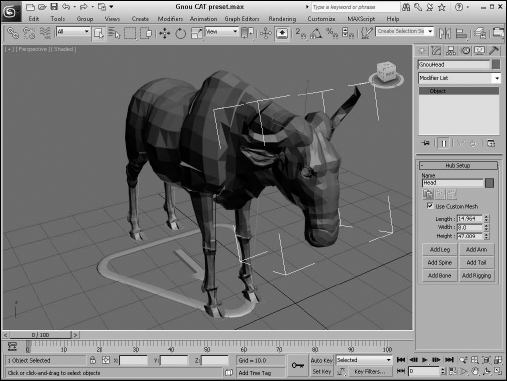
The bones that make up a CAT rig by default are simple box objects. This allows them to move quickly with a minimum amount of lag, but the bones don't need to be overly simple. The power of modern computers allows complex scenes to be animated without any lag. If you select a bone and enable the Use Custom Mesh option in the Setup rollout, you can access and modify the existing bone to be more representative of the mesh.
To edit an existing bone, simply apply a modifier to the bone object or an Edit Poly modifier and edit the bone as you wish. You also can attach another mesh to the Edit Poly modifier. Once editing is done, simply collapse the changes to the base bone object, and then you can switch back and forth between normal box bones and the custom mesh using the Use Custom Mesh option. Figure 39.4 shows the preset for a gnou.
If you've gone to all the trouble of building a skin mesh, then you can quickly use the same skin mesh as the skeleton by stripping down its details and using it as a custom mesh.
FIGURE 39.4 Simplified meshes can be used as custom rig bones like this gnou preset.
Tutorial: Editing the head bone
Starting with the alien preset CAT rig, this example edits the alien's head bone to show more character and to demonstrate how custom meshes can be used.
To edit the head bone on a CAT rig, follow these steps:
- Open the Custom alien head bone.max file from the Chap 39 directory on the CD. This file includes the Alien CAT preset rig.
- Select the head bone and open the Modify panel. Enable the Use Custom Mesh option in the Hub Setup rollout.
- Apply the TurboSmooth modifier from the Modifier list and scale the head object up to match the other bones.
- Open the Create panel and select the Sphere button. Enable the AutoGrid option at the top of the Object Type rollout and drag on the surface of the head to create two eyes and a nose.
- Open the Modify panel again, select the head bone, and apply the Edit Poly modifier to the object. Then click the Attach button and pick the two eyes and nose objects to combine them to the head object.
- Right-click in the Modifier Stack, select the Collapse All option from the pop-up menu, and click Yes in the warning dialog box that appears.
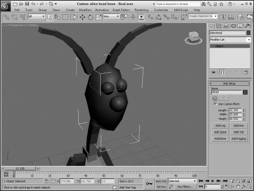
Figure 39.5 shows the custom alien head bone. You can switch back to the default box bone by disabling the Use Custom Mesh option.
FIGURE 39.5 Bones can be replaced with custom mesh objects.
Building a custom CAT rig
When building a custom CAT rig, start with the CAT Parent object, but make sure the None option is selected in the CAT Rig Load Save rollout. Then, right-click in the viewport to exit CAT Parent creation mode. This creates the parent without any rig. Position the CAT Parent object so both feet of the skin mesh are contained within the parent's outline.
Tip
If you make the skin mesh object frozen and enable the See-Through option in the Object Properties dialog box, you can easily place the rig bones where they need to be.
The first step in creating a custom CAT rig is to create the pelvis using the Create Pelvis button beneath the list of presets. The pelvis object appears as a simple box object above the CAT Parent object. You can then use the Transform tools to move, scale, and rotate the pelvis into place to match the skin mesh.
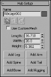
With the pelvis object in place and selected, you then have options in the Hub Setup rollout, shown in Figure 39.6, to add legs, arms, and a spine or a tail if you want. The Add Leg button adds to the pelvis a leg with two bones that extends to the floor and an ankle. You can position the leg bones by dragging the foot into position. When one of the legs is in position, you can select the pelvis again and click the Add Leg button again to create the opposite leg. The opposite leg is created using the same settings and position as the first.
FIGURE 39.6 The Hub Setup rollout includes buttons for creating connected legs, arms, and spine.
With the pelvis selected again, click the Add Spine button. This adds a set of spine bones with another hub object on top. The top hub object is used to connect the arms and the neck. The neck is simply another set of spine bones with a hub object on top for the head.
Note
For creatures with multiple arms and legs, the difference between the limbs is that a leg extends from the hub to the ground, and the arm hangs loosely.
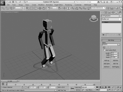
You can then select the pelvis, shoulder, or head hub objects and use the Add Tail button to add a tail, wings, or ponytail as needed. Figure 39.7 shows a custom CAT rig created with only a few clicks. The rig includes IK chains on both legs and FK chains on the arms. Fingers and toes could be added easily by selecting the palm or ankle objects and specifying the number of digits.
Naming CAT bones
When bones are added to a CAT rig, they are automatically named using the text entered into the Name field. The default name of the entire rig is taken from the name entered into the Name field when the CAT Parent is selected, and names for each body part are associated with the various object parts such as RLeg and LArm. Each bone within a chain is given a default number, so the upper arm object is labeled as 1 and the lower arm is 2.
FIGURE 39.7 Custom CAT rigs are easily created using the CAT tools.
If you change the name field, all bone names that are affected by the name change are automatically updated, so changing the Name field in the CAT Parent to Reuben automatically changes all bones to start with this name. This makes keeping track of all the various bones much easier and intuitive. It also helps when you start to animate the rig.
Tutorial: Building a custom CAT rig to match a skin mesh
For this example, we use the CAT tools to create a custom rig that matches a mesh skin. The chosen mesh skin is none other than Marvin Moose.
To create a custom CAT rig, follow these steps:
- Open the Marvin Moose.max file from the Chap 39 directory on the CD. This file includes the Marvin Moose skin mesh positioned at the origin.
- Select and right-click the moose skin mesh object, and select the Object Properties option from the quadmenu. Enable the See-Through and Freeze options in the Object Properties dialog box.
Tip
The keyboard shortcut for making an object see-through is Alt+X.
- Click the Helpers category, open the CAT Objects subcategory in the Create panel, click the CAT Parent button, and drag in the viewport to create the object. Make the CAT Parent just big enough to contain the moose's feet.
- With the CAT Parent object selected, open the Modify panel and click the Create Pelvis button. Then select and resize the pelvis object and position it to match the skin mesh.
- With the pelvis object selected, click the Add Leg button to create the left leg. Select and rotate the ankle so the foot is flat against the ground. Scale the foot to roughly match the skin mesh's foot.
- Select the pelvis, and click Add Leg to create the opposite leg; then click the Add Spine button to create the spine and an object for the shoulders. Position and scale the shoulder hub object. Select the shoulder hub object, and click the Add Arm button. Position the arm bones to match the skin mesh.
- Select the shoulder hub object, and click Add Arm to create the opposite arm; then click the Add Spine button to create another spine and an object for the head. Select one of the new spine bones, and change the name to Neck and the number of bones to 2. Then scale the head bone to match the moose's head and horns, and name the head bone Head.
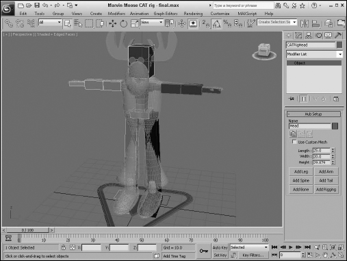
Figure 39.8 shows the completed custom CAT rig ready to be skinned and animated.
FIGURE 39.8 The moose's skin has been rigged using the CAT tools.
Animating a CAT Rig
The best rig in the world doesn't do you much good if you can't animate it well. Luckily, CAT's animation tools are excellent, just like its rigging tools. CAT uses the concept of animation layers to hold its animation keys. This allows you to blend between different motions.
Cross-Reference
Animation layers are also discussed in Chapter 35, “Using Animation Layers, Modifiers, and Complex Controllers.”
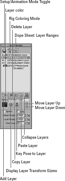
All the animation controls for CAT rigs are found in the Motion panel whenever any of the rig's bones are selected. Within the Layer Manager rollout, shown in Figure 39.9, is a list of the available animation layers. To create a new animation layer, select from four different types, using the Add Layer drop-down list at the bottom right of the list. The four animation layer types include the following:
- Absolute Layer: Holds animation key data that defines full motions
- Local Adjustment Layer: Holds relative key data relative to the local coordinate system of the above layer
- World Adjustment Layer: Applies relative motion in world space that is independent of the previous layers
- CAT Motion Layer: Creates procedural-based looping motion such as walk cycles
After an animation layer is added and selected, you need to press the Setup/Animation Mode toggle button to begin adding keys to the selected animation layer. You do this using the Auto or Set Key modes to create the keys like normal. Any time a new animation is added, it is automatically placed above the currently selected animation layer.
Tip
If you're animating some of the rig bones using Auto Key and the keys don't appear on the Track Bar, check to make sure you have clicked the Setup/Animation Mode toggle button to enable animation.
The selected animation layer can be removed from the list using the Delete Layer button. You also can copy and paste layers between different rigs using the Copy and Paste Layer buttons. The Move Layer Up and Move Layer Down buttons are used to reorder the selected layer. Each layer can be given a unique name using the Name field.
The Ignore option disables the selected animation layer, and the Solo option disables all animation layers except for the current selection.
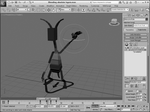
Blending absolute animation layers
When several absolute animation layers are added, the layers are evaluated according to their order in the Layer Manager list from top to bottom. Each layer can have a Global Weight value that determines how much of the animation layer is blended.
For example, if the top absolute animation layer contains keys for a character raising an arm, and a second absolute animation layer is added that has keys of the character waving its hand, these two can be blended to create the combined motion of the character raising its hand and waving by setting the Global Weight for the second absolute animation layer to 50 percent, as shown in Figure 39.10. If the second layer is set to 0 percent, the character simply raises its arm; if the Global Weight of the second layer is set to 100 percent, the layer takes over the entire animation and the character waves its hand without raising its arm.
FIGURE 39.9 The Layer Manager rollout holds the various animation layers.
In addition to the Global Weight value, which affects all parts of the rig, you can also set a Local Weight value for specific bones. For example, if an absolute animation layer is set that moves the rig to a specific pose, you select the left collar bone and set its Local Weight to be a percentage of the final pose. The Local Weight setting lets you control individual bones and limbs differently from the global animation layer.
FIGURE 39.10 If the Layer Manager contains multiple animation layers, you can blend between them using the Global Weight values.
Another helpful tool as you begin to animate your rig is the Rig Coloring Mode option located to the right of the Set/Animation Mode toggle button. If you switch the Rig Coloring Mode to display Layer Colors, then the color of the rig matches the color of the animation layer; if two layers are blended together, then the color of the rig also is mixed. If a specific bone is given a different Local Weight, then that bone is colored the same as the animation layer that is controlling it.
Tip
If you plan to blend layers, setting each layer to use a primary color makes it easier to see where layers are blended when the Layer Colors option is enabled.
Clicking the Dope Sheet: Layer Ranges button opens the Dope Sheet with the ranges of the various animation layers displayed. This provides an easy way to modify the ranges for the different animation layers. You also can access the Curve Editor for each of the Global and Local Weights using the button to the right of the respective weight values.
You can use the Display Layer Transform Gizmo button for each layer. This creates a simple helper object that is linked to the character. It can be moved and rotated to control the entire rig. The gizmo is normally placed at floor level between the rig's feet, but if you hold down the Ctrl key while clicking this button, the gizmo is placed at the current bone; if you hold down the Alt key, the gizmo is placed at the world origin. This gizmo is available only for absolute animation layers.
Using adjustment animation layers
If you have your animation layers working just right with the motion you like, but your animation needs a little more exaggeration or a hand needs to reach just a little farther to grab a doorknob, then you can return to the base absolute layer and make the change, or you can apply an adjustment layer.
There are two different adjustment layer types: local and world. The difference is in how they are affected by the previous animation layer. Local adjustment layers add the adjustment layers changes onto the above layer's motion, so if a local adjustment layer has a hand reach forward a little more, the motion is added to the existing motion.
World adjustment layers work in world space and cause the hand to reach to a specific location in the world. This still blends with the previous layer's motion, but it also moves the selected object to a global position.
Creating a walk cycle with a CAT motion layer
Keyframing absolute animation layers is okay, but it can be tedious. The CAT Motion layer is where the fun really begins. Adding a CAT Motion layer to the list automatically applies a walk cycle to the rig. This is done without having to create any keys; just press the Play button, and you see the default walk cycle.
When a CAT Motion layer is selected in the Layer Manager rollout, the CAT Motion Editor button appears to the right of the layer color swatch. This button opens the CAT Motion dialog box, shown in Figure 39.11. Using this dialog box, you can adjust the parameters of the walk cycle.
FIGURE 39.11 The CAT Motion dialog box lets you alter the walk cycle parameters.
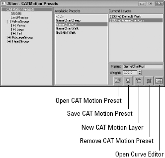
The first panel of the CAT Motion dialog box presents a list of available presets. The buttons at the lower-right corner of the dialog box let you open saved presets. You also can name and save custom presets. The CAT Motion dialog box has its own set of animation layers that are listed in the rightmost pane. Double-clicking a preset opens a simple dialog box with options to load the preset into a new layer or into the existing layer.
The layers work just like those in the Layer Manager rollout with weights assigned to each layer. For example, if you add the default walk cycle and then a new run cycle set to 50 percent, the run cycle is blended with the walk cycle, creating a slower run cycle. You also can open the Curve Editor to change the shape of the weight curves.
Setting global parameters
Clicking the Globals option in the leftmost pane of the CAT Motion dialog box opens a panel of global CAT motion parameters, shown in Figure 39.12. At the top of the global parameters are settings for changing the start and end frame of the walk cycle. Note that these settings are different from the start and end time settings in the Time Configuration dialog box, and they affect only the CAT rig motion.
FIGURE 39.12 The Globals panel of the CAT Motion dialog box lets you change the walk tempo, speed, and direction.
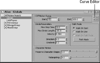
The Max Step Time defines how quickly each step is taken. Low values make the character walk crazy fast, and higher values make a slower, more casual walk. The Max Stride Length sets the distance of each step. These two values together determine the Velocity, but you can't alter the Velocity setting.
The character by default is pointing in the direction indicated on the CAT Parent object, but you can alter the direction that the character is walking by altering the Direction value. A setting of 0 makes the character walk in the direction he is pointing, a value of 90 makes the character shuffle to his right, a value of 180 makes the character walk backward, and a value of 270 makes the character shuffle to the left. The Gradient setting controls the angle that the character is pointing. Negative values make the character point forward as if walking down a hill, and large, positive values make the character walk as if going up a hill.
Walking along a path
The default is to have the character walk in place, but if you select the Walk On Line option, then the character walks forward in a straight line. When the range of frames is reached, the character returns to its starting position and walks the line again. If the Direction value is changed, the character moves straight in the specified direction.
If you click the Path Node button, you can choose a scene object that the character will follow. For example, if you make the Path Node a dummy object, then the character is positioned and walks on top of the dummy object. You can then animate the movement of the dummy object in the scene, and the character follows it.
To make the character walk along a path, you simply need to create a path using the Line tool. Then select the dummy object and use the Animation ![]() Path Constraint menu to attach the dummy object to the path. If you enable the Follow option in the Motion panel after making the link, the character turns to stay on the path.
Path Constraint menu to attach the dummy object to the path. If you enable the Follow option in the Motion panel after making the link, the character turns to stay on the path.
When having a character follow a path with tight corners, the character may become distorted as it attempts to stay on the path. The Preserve Character Shape setting lets you minimize the distortion. A setting of 0 allows the distortion caused by tight corners.
Controlling footsteps and limbs
The Limb Phases panel of the CAT Motion dialog box, shown in Figure 39.13, controls the placement of footsteps and the swing of each leg and arm. The footprints that appear when a character is walking are tied to the rig, so altering the footsteps also alters the rig. If the footsteps don't appear when you select a walk cycle, you can use the Create button to make them appear. You also can delete them with the Delete button. If you move or rotate any of the footsteps, you can use the Reset button to remove any changes for All footsteps or for just the selected footsteps.
FIGURE 39.13 The Limb Phases panel lets you set how the arms and legs swing relative to each other.
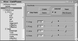
The sliders for each leg and arm at the bottom of the Limb Phases panel let you alter how the arms and legs swing relative to each other. By default, the opposite leg and arm swing together, but you can alter these sliders to give the walk cycle a different look.
Matching footsteps to the ground
After footsteps appear, you can select them and use the Pick Ground button. This lets you select a ground plane object. This ground object needs to be a single object, but once selected, the footsteps are moved vertically to align to the ground plane, causing the character to walk along the surface of the ground.
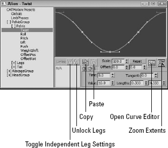
Controlling secondary motions
The remaining panels in the CAT Motion dialog box are used to control the motions of the other rig groups, such as the pelvis, head, and ribcage. If you open the Pelvis group, you see several parameters that you can access including Twist, Roll, Pitch, Lift, Push, Weight Shift, and positional and rotation offsets. Each of these parameters shows an animation curve that you can use to exaggerate or calm the selected motion, such as the Twist parameter shown in Figure 39.14.
FIGURE 39.14 Using the parameter curves in the CAT Motion dialog box, you can control motions such as the twisting of the pelvis.
Tutorial: Animating a character walking along a path
In this example, you take the default alien character rig and make it walk along a drawn path.
To animate a character walking along a path, follow these steps:
- Open the Wandering alien.max file from the Chap 39 directory on the CD. This file includes the default CAT alien rig and a random path.
- With the alien rig's parent object selected, open the Motion panel and add a CAT Motion animation layer to the Layer Manager list. Then click the Animation Mode button. If you click the Play button, you can see the alien walk in place.
- Click the Helpers category, and create a dummy object.
- Select any part of the rig again, and click the CAT Motion Editor button in the Motion panel. Select the Globals panel, and click the Path Node button. Then select the dummy object in the scene.
- With the dummy object selected, move and rotate the character so it's facing the starting end of the path. Then select the Animation
 Path Constraint menu, and click the path. Open the Motion panel, and enable the Follow option in the Path Parameters rollout. You need to rotate the dummy object to align the character with the path again.
 - Click the Play button; the character walks along the path, and footsteps mark each step the character takes.
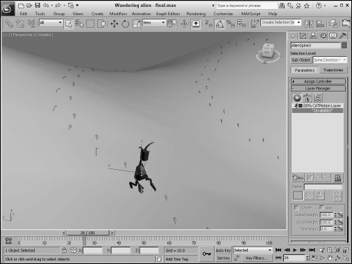
- Select the File Import Merge menu command, and merge the object in the Hilly surface.max file into the current scene. This curvy surface appears as a ground plane. Select the character rig and in the Limb Phases panel of the CAT Motion dialog box, click the Pick Ground button and select the ground plane. The footsteps rise to match the ground plane, as shown in Figure 39.15.
FIGURE 39.15 Constraining the path node to a path makes the character walk along the path.
Working with Muscles
Bones are great for controlling rigid motion, but they don't help much when it comes to creating muscle bulges or the fluid motion of skin moving over muscles. CAT has solutions for these cases also in the form of two different types of muscles. Muscle strands are composed of a set of spheres that squash and stretch when their end points are linked to bones. The second muscle type is a series of rectangular panels that flow and move together.
Both muscle strands and CAT muscle objects are created using their respective buttons in the CAT Objects subcategory of the Helpers panel in the Command Panel.
Note
Generally, muscle strands are used on the arms and legs, and CAT muscles are used for the abdomen, chest, and shoulders.
Using muscle strands
Muscle strand objects are created by clicking in the viewport to place control handles. A single muscle strand has four unique handles, divided into two sets. Click and drag to create the first set and repeat to create the second set. The first and last handles mark the end points of the muscle strand, and the middle two handles can be moved to affect the position of the center line of the muscle. The handles can be made visible or hidden, or you can change their size using the settings in the Muscle Strand rollout.
Using the options in the Muscle Strand rollout, you can set the muscle to replace an existing bone in the rig with the Bones option, or you can include the muscle strand with the bone and use the Skin Wrap modifier to drape the skin mesh over the muscle with the Mesh option.
The Muscle Strand rollout also includes buttons for copying and pasting properties between muscles and for setting the muscle as a left, middle, or right side of the body. You also can set a mirror axis for the muscle.
The shape of the muscle is determined by the number of spheres that gradually get larger and then smaller again as you traverse the muscle length. You can change the number of spheres included in the muscle or set the size of each individual muscle sphere. The Show Profile Curve button displays the profile curve for the muscle in a window that you can edit.
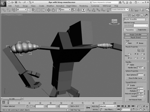
Once the muscle is in place, you can link its end points to the nearby bones using the standard Link tool found on the main toolbar. Within linked end points, the muscle compresses and stretches as the bones are moved. You also can enable the Squash/Stretch feature in the Muscle Strand rollout to add this behavior to the muscle. The midpoint for the squash and stretch is set using the Set Relaxed State button.
Figure 39.16 shows the Ape rig preset with two muscle strands inserts for the rig's upper arm bones. Notice how the right arm bulges when the forearm is brought forward.
FIGURE 39.16 Muscle strands provide the bulging effect of muscles.
Using CAT muscles
CAT muscle objects are composed of sheets of rectangles that move and slide relative to each other. They are created by dragging out a rectangle area much like a plane object. Each corner of the CAT muscle has a handle, and several interior handles are also available for deforming the muscle. You can hide the corner handles or the middle handles, or you can set their size using the settings in the Command Panel.
Just like muscle strands, you can specify that the CAT muscles are either Bones or Mesh objects. The resolution of the muscle plane is set using the U and V Segs, which can be increased for greater resolution. Once the CAT muscle is in place, you can link its corners to the rig bones, and the plane deforms as the attached bones are moved.
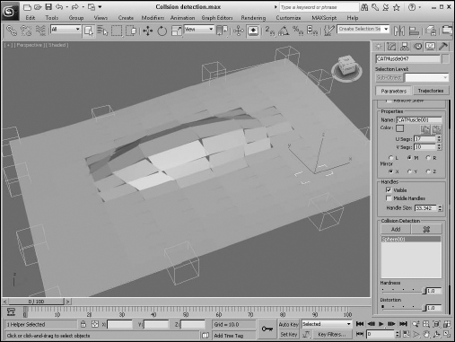
CAT muscles include another really nice feature: collision detection. This lets you place objects underneath the CAT muscle and add them to a list of objects for collision detection. The result is that the muscle is molded to fit the underlying object. The collision object can be any standard object or even a muscle strand object. Figure 39.17 shows a CAT muscle that is being molded by an elongated sphere. For each collision object, you also can set the Hardness and Distortion values.
FIGURE 39.17 CAT muscles provide a way to simulate flatter rows of muscles.
Tutorial: Adding muscles to a rig
In this example, you take the default human character rig and add a CAT muscle to the front for the chest and stomach definition.
To add muscles to a rig, follow these steps:
- Open the Human char with muscles.max file from the Chap 39 directory on the CD. This file includes the default CAT human rig.
- Open the Create panel and choose the Helpers category and the CAT Objects subcategory. Click the CAT Muscle button and drag in the Front viewport to create a CAT muscle that runs from the collar bone to the pelvis on the left side. Then move the muscle plane into position in front of the ribcage bone.
- Open the Modify panel and set the U and V Segs values to 15. Select and move the outer corners and their adjacent handles to make the muscles bend around the side of the body.
- Select Create Extended Primitives Chamfer Box menu and drag to create a box with rounded corners. Then create and elongate a sphere object with the Create Standard Primitives Sphere menu. Position the rounded box at the location of the pectoral muscle. Position and clone the sphere to show three rows of stomach muscles.
- Select the CAT muscle object, and in the Modify panel click the Add button for the Collision Detection section, and select the rounded box and sphere objects. Then move the collision objects to create the desired muscle look in the CAT muscle.
- Select each of the collision objects, right-click, and choose the Hide Selected option from the pop-up quadmenu.
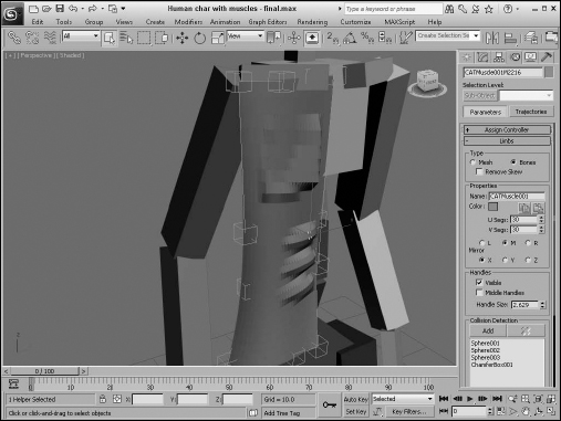
Figure 39.18 shows the CAT muscle with some deformation for the pec and stomach muscles.
FIGURE 39.18 The CAT muscles can be used to create muscle deformations.
Summary
This chapter serves as an introduction to CAT and covers all aspects of working with CAT rigs, including its presets, custom rigs, and animation. The following topics were covered:
- Learning the basic workflow for creating characters
- Creating and editing CAT rigs
- Creating a custom CAT rig
- Animating CAT rigs
- Creating walk cycles with the CAT Motion dialog box
- Using muscle strands and muscle planes
Whether you're using a custom rig or a CAT rig, the next step is to begin the skinning process, which is covered next. Skinning surrounds the skeleton with a mesh skin and matches the way the skin aligns and moves with the underlying rig.