
BONUS CHAPTER 20
Quick Start—3ds Max 2011 Bible: Animating a Walking Dinosaur
Planning the production
Gathering models
Applying materials
Adding a Sun & Sky system
Animating a CAT rig
Rendering the final animation
When you first got your hands on 3ds Max, you were probably focused on one goal—creating cool 3D images and animations. I know that many of you bought Max to make money, claim a tax write-off, earn a way to Hollywood, or impress your girlfriend or boyfriend, but I'll just ignore those reasons for now. The goal is to create something cool.
If you've perused this book's Table of Contents or thumbed through its many pages, you've seen sections on modeling, materials, dynamics, and other topics. But if you're like me, you don't want to wade through tons of material before you have something to show off to Mom. (Actually, if you're like me, you opened straight to the special effects section, in which case you won't be reading this.)
The purpose of this Quick Start is to give you a taste of what Max can do. This soaring view of the software from 20,000 feet is intended to show you the big picture before you delve into the details. It exposes you to some of the most common features and, I hope, whets your appetite for the more in-depth chapters to follow.
This part of the book is intended for those new to the software. If you're an experienced user, then your mom no doubt is already impressed with your work, so you can happily advance to whichever chapter appeals to you. (Forgive me for catering to the newbie, but we were all beginners once.)
Walking Dinosaur—Planning the Production
For this Quick Start, you're going to animate a dinosaur walking across a landscape. This gives you a chance to set up a scene, work with a character rig, and do a little animation.
The first thing to consider is setting up the scene. For this sequence, we need a dinosaur and a landscape for it to walk on. We need to model these two critical pieces, but we're going to cheat. Yes, that is allowed, because it saves us some time. If you can locate some models that fit your needs without having to model them, then you are ahead of the game. The book's CD includes a large number of models created by professionals to get you started, including conveniently an allosaur dinosaur.
We also want the background and the ground plane for this scene. For the background, we use a Daylight system, which not only gives us nice outdoor lighting but also a horizon effect that works for this scene. For the ground plane, we use a flat plane object with a noise modifier applied to it to give it a random texture. Because both of these scene elements are generated by Max, we don't need to locate a background texture.
For the animation phase, we use a preset rig included with CAT that gives us the ability to animate the dinosaur walking. The plan is to have the dinosaur walk toward the camera, stop and look, and then walk away.
Finally, for lighting, you want to use a lighting model that works well for outdoor scenes, and the Daylight system works well.
On the CD-ROM
After each of the following tutorials, I saved the scene file. You can find these files in the Bonus Chapter 20 directory on the book's CD.
Setting Up the Scene
This section on setting up is divided into several simple tutorials. The first step in the production is to pull in all the models we need. Then we can position them where we need them. We also want to position our camera in a good spot.
After the models are in place, we can create the ground plane, and then we're ready to add some materials and lights.
Tutorial: Gathering models
Your first step begins with the task of loading into a single scene all the models that we're using. This also involves scaling them so they are the right size relative to each other.
To load the models, follow these steps:
- Reset the interface with the Application Button
 Reset menu command. Answer Yes in the warning box that appears.
 - Use the Application Button Open menu command, and locate the Dinosaur.max file from the Bonus Chapter 20 directory on the CD.
Note
This chapter uses Generic Units. You can change the units using the Units Setup dialog box, which you open using the Customize
Units Setup menu command. - The dinosaur model is right in the middle of the scene and consists of several parts. We need to combine all the parts into a single object in order for the dinosaur to move altogether. Click the body to select it.
- The body object is an Editable Poly object type, which you can see if you open the Modify panel. Click the small dialog box to the right of the Attach button in the Edit Geometry rollout. In the Attach List that opens, select all objects and click the Attach button.
- The Attach Options dialog box appears. Because the material and color applied to each of the parts is different, this dialog box lets you specify what to do with the different materials. Select the Match Material IDs to Material option, and click the OK button. This combines all parts to the body object without losing any of the materials. You now have a dinosaur skin mesh that you can attach to a skeleton for animating.
- Click the Maximize Viewport Toggle button in the lower-right corner of the interface to increase the size of the active viewport.
The dinosaur model is loaded and ready to work with, as shown in Figure 1.
FIGURE 1 The dinosaur model is loaded and combined into a single object.

Tutorial: Adding a ground plane
With the dinosaur model loaded, we next add a ground plane to the scene. This can be a simple plane object, and we want to apply a Noise modifier to give it some bumps.
To add a ground plane, follow these steps:
- Click the Maximize Viewport Toggle again (or press Alt+W again) to see all four viewports.
- Click the Top viewport, and zoom out. Then select the Plane button in the Command Panel to the right and drag from the upper-left corner to the lower-right corner in the Top viewport to create a large plane object. In the Create panel, set the Length Segs and Width Segs to 30 to increase the plane's polygon density.
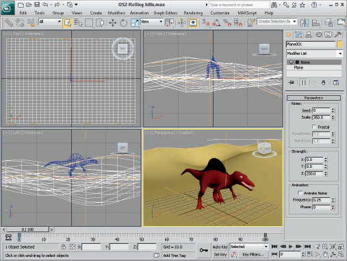
- With the plane object still selected, choose the Modifiers Parametric Deformers Noise menu to apply a Noise modifier to the plane object. Then in the Parameters rollout, set the Scale value to 350 and the Z Strength value to 200.
The ground plane with a Noise modifier creates a nice landscape of rolling hills, as shown in Figure 2.
FIGURE 2 The scene now has a ground plane of rolling hills.
Adding Materials and Lights
The modeling phase, which is usually quite time-consuming, went really quickly when we used existing models. The next phase is to add materials to the models and lights to the scene. Because our models have applied materials already, this phase also goes pretty quickly.
One key change to make is to switch the default Scanline rendering engine to the mental ray rendering engine. This makes available a wider assortment of materials and improves the subtle details of reflections and refractions in the scene. It also improves our lighting.
Tutorial: Enabling mental ray and adding materials
After the modeling is complete, you can add materials to the objects to improve their look. Materials are added using the Material Editor, which is opened using the Rendering ![]() Material Editor
Material Editor ![]() Slate Material Editor menu command or by pressing the M keyboard shortcut.
Slate Material Editor menu command or by pressing the M keyboard shortcut.
Max includes a special set of materials that are used to dress up buildings and architectural designs called the Autodesk Material Library, but they require that the mental ray render engine be enabled. After the mental ray render engine is enabled using the Render Scene dialog box, you can access the Library in the Material/Map Browser.
To add materials to the desert ground plane, follow these steps:
- Select the Rendering Render Setup menu command (or press F10) to open the Render Setup dialog box. At the very bottom of the Common panel is the Assign Renderer rollout. Within this rollout, click the button to the right of the Production Renderer and then double-click the mental ray Renderer option in the Choose Renderer dialog box that opens. Then close the Render Scene dialog box.
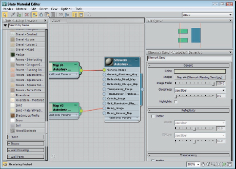
- Select the Rendering Material Editor Slate Material Editor menu command (or press the M key) to open the Material Editor. Locate and double-click the Sand material in the Material/Map Browser. It is located in the Sitework folder of the Autodesk Material Library. The nodes for this material are displayed in the Material Editor.
- With the ground plane selected in the viewports, click the Assign Material to Selection button in the toolbar of the Material Editor. This applies the material to the selected object.
The rest of the models have materials already, so we can move on to lights. Figure 3 shows the Slate Material Editor.
FIGURE 3 The Material Editor lets you configure and apply materials to scene objects.
Tutorial: Adding a Sun & Sky system
Another benefit of having the mental ray renderer enabled is that you also can use the Sun & Sky system. This system simulates outdoor lighting from a distant source like the sun and generates a sky for the background.
To add a Sun & Sky system to the scene, follow these steps:
- Select the Create Lights Daylight System menu command, and drag in the Top viewport to add a compass helper to the scene. Then click and drag to position the Sun light icon in the Top viewport.
Note
When the Daylight System is applied, a dialog box automatically appears, recommending that you use the Logarithmic Exposure Control and asking whether you want to make this change. Click Yes to continue.
- Select the Rendering Environment menu command (or press the 8 key) to open the Environment and Effects dialog box. Click the Environment Map button, and select the mr Physical Sky map from the Maps/mental ray folder in the Material/Map Browser. Then enable the Use Map option, and close the Environment dialog box.
- Choose the Views Viewport Background Viewport Background menu command (or press Alt+B) to open the Viewport Background dialog box. Select the Perspective viewport, enable the Use Environment Background and the Display Background options, and close the dialog box.
- Click the Maximize Viewport button in the lower-right corner of the interface (or press Alt+W) to make the Perspective viewport full sized.
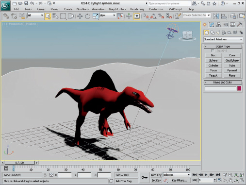
- With the daylight light selected, click the Setup button in the Daylight Parameters rollout found in the Modify panel. Then set the Time Hours to 11. This sets the time of day to late afternoon.
- To see the lights and shadows in the viewport, click the viewport shading label in the upper-left corner of the viewport, and select the Lighting and Shadows Enable Hardware Shading (or press Shift+F3). Then turn on Enable Exposure Control in Viewport, Enable Shadows, and Enable Ambient Occlusion in the same Lighting and Shadows menu.
The viewport now shows the scene with a background sky, as shown in Figure 4.
FIGURE 4 The sky background is visible within the viewport.
Tutorial: Rendering a preview
Before moving to animation, you can render the scene now that lights have been added. Rendering is configured using the Render Scene dialog box.
To render a preview of the dinosaur scene, follow these steps:
- Select the Rendering Render menu command (or press the F10 key), and open the Indirect Illumination panel. Turn on the Enable Final Gather option, and set the Preset to Medium. This computes a global illumination model by determining how light rays bounce about the scene.
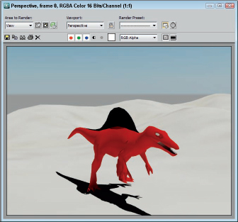
- Back in the Common panel of the Render Scene dialog box, select the image size in the Common Parameters rollout and click the Render button. The active viewport is rendered and displayed in the Render Frame Window.
Tip
This scene is fairly simply and renders quickly, but if you need the test render to be even faster, you can enable the Quicksilver Hardware Renderer instead of the mental ray.
The rendered dinosaur image, as shown in Figure 5, includes all the materials and lighting effects.
FIGURE 5 The rendered image of the scene includes the lighting effects.
Animating the Dinosaur
With the test render complete, and the scene looking good, we can move to the animation phase. This phase involves adding a skeleton rig to the dinosaur using the Character Animation Toolkit (CAT) tools. The skeleton can be animated easily, causing the dinosaur mesh skin to follow.
Tutorial: Adding a preset CAT rig
The first step to animating a character is to add an underlying skeleton rig that matches the dinosaur's mesh. After this is done, the task of animating is quick.
To add a preset CAT rig to the dinosaur, follow these steps:
- Click the Maximize Viewport toggle button in the lower-right corner of the interface to toggle back to four viewports. Then zoom out of the Top viewport so you can see the entire scene.
- Select the dinosaur object, and choose the Edit Select Invert menu; then right-click in the viewport, and choose the Hide Selected option in the pop-up quadmenu. This hides everything but the dinosaur.
- Open the Create panel, and select the Helpers category. Then select the CAT Objects subcategory. Click the CAT Parent button, select the Allosaur preset, and drag in the Top viewport until the CAT rig is aligned with the feet and as high as the dinosaur's back in the Left viewport.
- With the Move tool in the main toolbar, select the left rig foot in the Front viewport and drag it to the left to align with the skin mesh foot. Then move the upper and lower left leg bones in the Left viewport forward to match the skin mesh leg.
Tip
If you find that you're selecting the skin mesh too much, you can right-click it and select Freeze Selection to freeze it so it can't be selected. Use the Unfreeze All option to unfreeze it when you're finished.
- Use the Front and Left viewports to move the bones of the rig arm to match the arms of the skin mesh for only the left arm.
- Open the Modify panel, and select the left upper leg bone, and then click the Copy Bone Settings button in the Ankle Setup rollout. Then select the right ankle bone and choose the Mirror Bone Settings buttons. This makes the bone changes on the left leg applied to the right. Then repeat this step for the arms.
- Select and drag the head bone forward in the Left viewport to align with the skin mesh's head. Select one of the tail bones, and set the Num Links in the Tail Setup rollout to 5; then move and orient the bones to match the skin mesh.
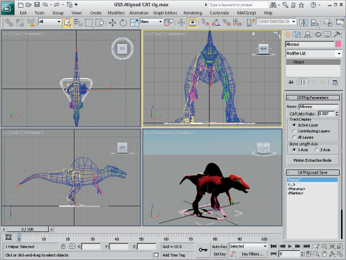
- After the rig is aligned to the skin mesh, select the skin mesh and choose the Modifiers Animation Skin menu command to apply the Skin mesh to the dinosaur. Click the Add button in the Parameters rollout, select all the objects in the Select Bones dialog box except for the Allosaur helper object and the two leg platform helper objects, and then click the Select button. Figure 6 shows the dinosaur with the CAT rig aligned to the skin mesh.
FIGURE 6 The CAT rig is aligned underneath the dinosaur skin mesh.
Tutorial: Creating a walking motion path
With the rig and the skin applied, you are ready to animate the dinosaur walking. This is where applying the CAT rig shows its usefulness.
To animate the dinosaur walking, follow these steps:
- Right-click in the viewport, and select the Unhide All option to make all scene objects visible again.
- Select the CAT Parent object, and drag it in the Top viewport to the upper-right corner of the plane object; then rotate it to face the center of the plane object.
- In the main interface along the bottom edge, locate the Time Configuration button and click it. In the Time Configuration dialog box, set the End Time to 300 and close the dialog box. This increases the frame range to 300.
- Select the Create Helpers Dummy menu command, and drag in the Top viewport to create a dummy object near the dinosaur's location. With the dummy object still selected, click the Auto Key button at the bottom of the interface, drag the Time Slider to frame 300, and move the dummy object across the viewport to the lower-left corner of the Top viewport. Then turn off the Auto Key button.
Tip
Remember to turn off the Auto Key button when you are finished animating, or you continue to create keys as you edit the scene.
- Select the CAT Parent object, open the Motion panel, click the Add Layers button beneath the layer's list in the Layer Manager rollout, and select the CAT Motion layer option. A new layer is added to the list.
- Click the Animation mode button located above the list in the Layer Manager rollout, and then click the CAT Motion Editor button below the list. In the dialog box that opens, select the Globals panel in the left pane, click the Path Node button, and then pick the animated dummy object. Keep the CAT Motion dialog box open for now.
- Select the dummy object and rotate it so the dinosaur is right side up and pointing in the direction that the dummy object is moving.
- Select the CAT Parent object again, and back in the CAT Motion dialog box, select the Limb Phases panel. Then click the Pick Ground button, and select the ground plane object in the viewport. This moves all the footprints for the CAT rig to follow the ground plane.
- Zoom out, and rotate the view in the Perspective viewport so the dinosaur is walking past the view.
- Click the Select by Name button in the main toolbar, select all the bone objects, right-click in the viewport, and select the Hide Selected option to hide all the bones.
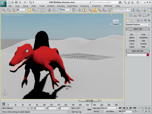
Click the Play button to see the resulting walk cycle added to the dinosaur. Figure 7 shows the walking dinosaur in the viewport.
FIGURE 7 The dinosaur walks over the hills using a lumbering gait.
Tutorial: Rendering the final animation
After the dinosaur walk looks good in the viewport, you are ready to render the final animation. This is a process that you can start by specifying the animation format. Once started, Max automatically proceeds through all the frames of the animation and notifies you when it is completed.
To render the final animation, follow these steps:
- Select the Rendering Render Setup menu command to open the Render Setup dialog box.
- At the top of the dialog box, enable the Active Time Segment so that all 300 frames of the animation are rendered. Then set the Output Size to 640×480.
- In the Render Output section, click the Files button to open a File dialog box. Set the format as AVI, give the file a name such as Walking Dinosaur, and click the Save button. In the AVI Compression Setup dialog box that appears, simply select the default compression and click OK.
- At the very bottom of the Render Setup dialog box, make sure the Perspective view is selected and click the Render button.
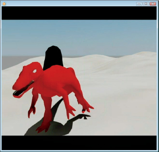
Max then renders each frame of the animation and shows its progress in a dialog box. When completed, the final animation file is saved with the filename you entered. You then can locate and play it. Figure 8 shows a frame of the final animation.
FIGURE 8 The final animation includes rendered results of each frame.
Summary
I hope you're happy with your first footsteps into Max. This chapter exposed you to a number of important aspects of Max, including the following:
- Setting up a scene
- Enabling mental ray
- Applying materials to scene objects
- Using the Sun & Sky system and enabling lights and shadows in the viewport
- Matching a preset CAT rig to a skin mesh
- Creating a walk cycle using a CAT Motion layer
- Render the final animation
But hold onto your seats, because so much of the software lies ahead. In Chapter 1, you start easily with an in-depth look at the Max interface. If you feel ready for more advanced challenges, review the Table of Contents and dive into any topic that looks good.