
5.11 Resistor Networks
Multiple terminating resistors are often supplied as a single in-line package or SIP. When resistors are used for series terminations, separate connections must be made to each resistor. Note that on a SIP package, a separate lead goes from the top of the resistor to the board for each resistor. To reduce lead length in short rise-time circuits, a DIP or dual-in-line package is preferred. Any short transmission line between the signal source and the resistor can add to the signal propagation time. For a SIP package, the ends of the resistors nearest the board should connect directly to the logic. This is another case where a field solver may be required to determine if the performance is adequate. In general, high speed circuits are easier to manage if the resistors are mounted individually and not in SIP or DIP packages. There are solutions where the resistors are buried in the board as a part of vias. Another solution involves surface-mounted components. The approach used is a cost versus performance issue.
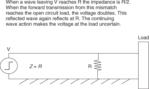
When parallel terminations are used, a group of resistors are often connected together at one end of the package. This common tie is then connected to the logic reference conductor, which is often the ground plane. The traces carrying the signals should terminate on their loads (logic gates) before reaching the resistor. If the termination is made in the reverse order, the result will be a short open-ended stub that connects to the load. Under these conditions, the voltage will attenuate at the resistor and double at the load and continue to reflect. The voltage at the load will be uncertain. This problem is shown in Figure 5.3.
Figure 5.3 The location of parallel terminations.
A problem exists when a group of terminating resistors shares a common tie. Assume that the common connection to the resistors is brought out at one end of the SIP. When all but one of the logic lines are at logic 1, the current in the common lead can be quite high. This problem is shown in Figure 5.4.
Figure 5.4 Common impedance coupling in resistor packaging.
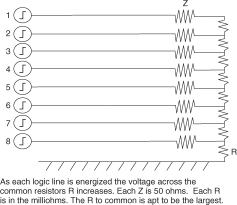
The voltage drop across this common impedance is an error signal. This error must be considered in any error budget analysis. To reduce the coupling, the ground connection can be made in the center of the SIP. The best solution is to connect all resistors to a conducting bar that bonds along its entire length to the ground plane. This technique eliminates any common impedance coupling.