
1.13 The Magnetic Field
The magnetic field that exists around a current is called an H field. This field is a force field that reacts against another magnetic field. The force field can be observed using a small compass or by noting the alignment of iron filings on a piece of paper that is threaded by a current carrying conductor. The Biot Savart's (Ampere's) law says that the line integral of H around any closed path is 4πI, where I is the current threading that loop. The value of H along the path of integration depends on permeability. In a high permeability part of the path, H is a low intensity field.
The H field is a vector field as it has intensity and direction at all points in space. The shape of the H field is usually represented by a series of curved lines. The H field intensity is the greatest where these curved lines concentrate. For a single round conductor carrying a steady current, the H field is represented by circles that surround the conductor (see Fig. 1.3 in Section 1.18).
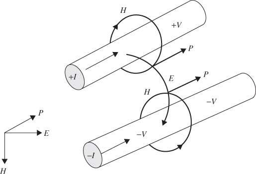
Figure 1.3 Poynting's vector for a pair of conductors carrying energy. E and H field vectors exist at all points in space. P = E × H. Note that P shows the density and direction of power flow at every point in space.
The second description of the magnetic field is the induction or B field. The induction measure of the field is needed whenever voltages are involved. The value of B in teslas is μ0μRH, where μR is the relative permeability of the material and μ0 is the permeability of free space equal to 4π10−7 teslas-meters per ampere. The voltage induced in any conducting loop of area A is the rate of change of the induction flux or A dB/dt. This is known as Faraday's law.
The flux generated by the induced current is always opposite in direction to the flux inducing the current. This is known as Lenz's law. The B field intensity does not change value at the boundary between regions of different permeability. The B field is always represented by closed continuous curves. At a boundary where the permeability changes, the B field may change direction but not intensity.
In electrostatics, a conductor geometry that is designed to store an E field is called a capacitor. In magnetics, a conductor geometry that is designed to store a B field is called an inductor. The definition of inductance is given as the B field flux generated per unit of current. The magnetic flux ϕ in any loop is the product of B field intensity and the area perpendicular to the direction of the flux.
The energy E stored in a magnetic field comes from accelerating charges into a current path creating the field. Consider an inductor with no current flow in the coil. At the start there is no magnetic field so no work is required to move the first increment of current into the coil of the inductor. For this analysis we must assume the resistance of the coil is zero ohms. When the second increment of current is added there is an existing magnetic field. The work required to establish the field in a volume V, where the field intensity is B, is
1.7 ![]()
In any practical geometry the B field is not constant, and the total energy must be calculated by an integration.
A magnetic field can be associated with an inductor or in the space around any current path. A magnetic field can be located in free space as a part of the radiation or it can be a part of the field in motion on a transmission line.
An inductor is a conductor geometry designed to store magnetic field energy. Measuring magnetic flux directly is very difficult, and, for this reason, inductance is usually measured by noting the voltage in the relation
1.8 ![]()
where dI/dt is the rate of change of current with respect to time. If V is in volts and dI/dt is in amperes per second then the inductance has units of henries. It is important to consider inductance as a field concept where the flux created by current flow is in the space around conductors. This is where the field energy is stored.
In a transmission line, the flow of current implies an associated magnetic field. The inductance per unit length of line will be an important factor in describing transmission lines. When a transmission line carries energy, there must be both an electric and a magnetic field in the space between the conductors.