
2.3 3D Scene Representation without Geometry – Image-Based Representation
Geometry-based representations use geometry primitives to represent objects in the scene, the content being transmitted from the sender to the receiver, and the receiver synthesizes the views by rasterizing the primitives with computer graphics techniques. However, the need of advanced graphics hardware for rendering and the lack of realism in the synthesized views make these geometry-based methods not appropriate for 3DTV systems. Instead, original TV systems capture the real world in a single-planar-view high-definition video stream and the video can deliver realism to viewers. Thus researchers propose to extend the idea to capture the real world in a set of videos and then synthesize new views from these sets of videos in the receiver side to deliver the reality to the consumer. This idea is called image-based representation. The image-based representations are categorized into:
- single texture techniques: a single texture can represent the appearance of an object or the entire world by a single and connected surface such as a cylinder or a plane.
- multiple texture techniques: a multiple texture representation refers to using a set of original camera views to represent a 3D scene.
In the following, we will first give a mathematical description of the process, namely, the plenoptic function, and then we will discuss image-based representations.
2.3.1 Plenoptic Function
3DTV should be able to deliver the image content to each eye separately. Thus, we should first describe what our eyes can see, that is, what information about the world the light delivers to each eye. A dense set of light rays with various intensities at different frequencies fills the 3D space. The set of rays passing through a point in the space is mathematically described as a pencil. If a theoretical pinhole is positioned at a given point as shown in Figure 2.17, the pencil of rays reaching the retina will form an image. One eye can be simply described as a pinhole camera with the assumption that the aperture is infinitely small. Therefore, pictures can be described as capturing partial of rays in the world as shown in Figure 2.18. Let us continue this line of thought to consider the necessary parameters for describing these lighting effects. First, when the image taken by a pinhole camera is a gray-scale image, it gives us the averaging intensity of light over the wavelength of the visible spectrum passing through a single viewpoint at a single moment of time. In other words, it describes the intensity distribution of light rays passing through the lens and the distribution is denoted as I. The spherical coordinates, I(θ, ϕ), or the Cartesian coordinates of a picture plane, I(x, y), may be used to parameterize this distribution. (Figure 2.19; see discussion below).
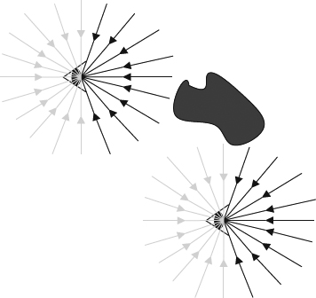
Figure 2.17 The plenoptic function describes the information available to an observer at any point in space and time. This shows two schematic eyes, which one should consider to have punctated pupils, gathering pencils of light rays. A real observer cannot see the light rays coming from behind, but the plenoptic function does include these rays.
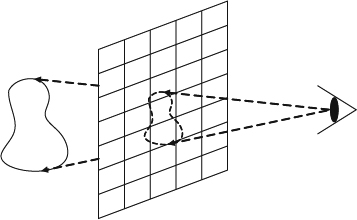
Figure 2.18 The image captures all the light rays shot from an object passing through the image.
The concept can be extended to a color image by adding an extra parameter to the intensity variation with wavelength, λ, and the description becomes I(θ, ϕ, λ). Extending to a color video and the equation becomes I (θ, ϕ, λ, t) by adding the time dimension, t. The equation above is used to describe the light information arrived at one point which is a specific world position. In order to describe the light arriving at any point in the world, the distribution function must be able to describe the observable light intensity at every viewing position (Px, Py, Pz) and the description becomes I(Px, Py, Pz, θ, ϕ, λ, t). This is a 7D function describing all view rays at all possible positions, at all possible moments and at all possible wavelengths. Therefore, the function allows reconstruction of all possible views in the world. The function is called the plenoptic function [99] and is the fundamental equation which can be used to describe the light intensity to reach each eye. It is also fundamental for all discussion in this section. In other words the plenoptic function implicitly contains all possible spatial-temporal views of the world (neglecting the polarization and instantaneous phase of the incoming light). Since the direction of gaze implicitly aligns with the orientation of the eye, the plenoptic function need not contain the specifications of the three viewing angles. According to the plenoptic function, some rays behind the eye may be blocked. The plenoptic function is intended to describe all the optical information potentially available at each point in space, as if the hypothetical eye had a 360 degree field of view. Figure 2.17 shows two possible examples from this function, with the eye placed at different positions in a scene. Thus, the plenoptic function can be measured by placing an ideal pinhole camera at all possible positions, (Px, Py, Pz), to record the intensity of the light rays arriving at all possible direction, (θ, ϕ), in terms of all wavelengths, λ, at every time t. The simplest setting is to let the pinhole camera always look at the z-axis of the world. The resulting function takes the form:
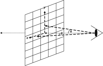
Figure 2.19 The image information available from a single viewing position is defined by the pencil of light rays passing through the pupil. The rays may be parameterized in angular coordinates or in Cartesian coordinates. The Cartesian approach is commonly used in computer vision and computer graphics, but the angular approach can more easily represent the full sphere of optical information impinging on a point in space.
where (Px, Py, Pz) is any position in 3D space, (θ, ϕ) is the arriving direction, t is the measurement moment, and λ is the frequency of the measurement. Thus, the equation describes the intensity of light rays with frequency, λ, reaching the position of (Px, Py, Pz) at the direction of (θ, ϕ) at time t. (θ, ϕ) is hard to define in the 3D space. Therefore, alternatively, the ray direction may be parameterized as the passing image (x, y) coordinates, where x and y are the spatial coordinates of an imaginary picture plane erected at a unit distance from the pupil. This is a commonly adopted approach in the graphics and vision community. The newly parameterized equations becomes:
where (Px, Py, Pz) is any position in 3D space, (x, y) is the pixel position in the image, t is the measurement moment, and λ is the frequency of the measurement. Thus, the equation describes the intensity of light rays with frequency, λ, reaching the position of (Px, Py, Pz) through the pixel of (x, y) at time t.
These two parameterization methods have their own advantages and disadvantages. The spherical parameterization more easily describes the fact that the light passes through a given position in 3D space from all directions at any moment of time. All directions are the same. However, the Cartesian parameterization is more familiar to users and more suitable to the current architecture and picture format and thus the following discussion will follow the Cartesian parameterization.
The plenoptic function is an idealized concept and cannot really be used to describe all possible rays in the world. Obviously it is impossible to record all this 7D light information from every possible point of view, for every wavelength, at every moment of time in the world, but the significance of the plenoptic function is to link the physical objects in the world with their corresponding images taken by a pinhole camera.
Image-based representation is to record the sparse sampling of the plenoptic function in a set of videos and try to synthesize the new view from the set of samples. Image-based rendering uses the view interpolation technique to reconstruct the plenoptic function [99] from the existing views.
The problem becomes how to recover the plenoptic function to allow us to synthesize the view from the set of images. Texturing 3D geometric objects is essential for realistic rendering in 3DTV applications. The texture of a real object is usually extracted from a set of images that capture the surface of the object from various angles. These images can either be processed and merged into a single texture representation or stored separately to be used as multi-textures.
2.3.2 Single Texture Representation
Single texture representation may use a single connected area or several isolated areas to represent the appearance of the surfaces in the scene or the object surface. The single connected area can be a 2D plane or a spherical surface and the true object surface is transformed to the representation. The connected representation is easily coded and transmitted along with the surface geometry information and eventually mapped onto the surfaces during rendering. They can be compressed more efficiently due to the high correlation among neighboring pixels but they cannot be generalized to represent objects with arbitrary topology. Therefore, Hndrik et al. [100] propose the usage of several isolated areas for each part of a 3D object. Figure 2.20 gives an example of using a texture atlas in a single texture for modeling the appearance of an object with no topology limitation. However, the compression is less efficient because of limited correlation. The representation of both methods must be static in terms of different lighting and reflection effects during navigation, which is a limitation of these representations. There are a large number of applications available in computer graphics and computer vision. In the followings, we give two famous examples that apply this concept:
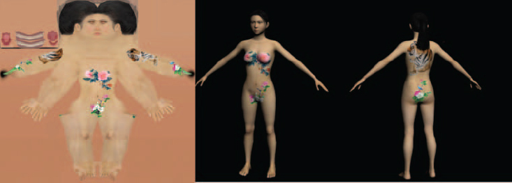
Figure 2.20 This demonstrates a concept of single object with multiple patches. The girl's body is textured with two patches of texture.
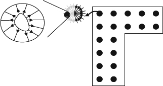
Figure 2.21 This demonstrates the grid points for an indoor scene of QuickTime VR. The black dots at the right are the positions of bubbles which represent the looking outward views. The bubble points may contain a hot point for interesting objects as shown in the left corner represented by looking inward views.
- QuickTime VR
As shown in Figure 2.21, there are two possible viewing situations: looking outward and looking inward.
- Looking outward condition assumes that all interesting objects are far away and thus the center view can be used to approximate the view.
- Looking inward assumes that the object is at the center and the blocking condition does not happen.
This concept is good for a navigation system in a closed environment such as a museum. The first step is to lay down a grid for a possible hub in the possible navigation areas. After laying down the grid points, at each point a set of images will be taken using a panoramic tripod to ensure the seamless stitching. In addition the designers also lay down the hot spots for the interesting objects which are taken using a sphere looking inward method. Then the bubbles and hot spots are oriented and recorded in the disk space in the QuickTime format. During navigation, the users use the control means to hop around the grid points and allow changes of the view direction. The grid position is used to retrieve the proper bubbles and the direction is used to synthesize the new view from the bubble for navigation. When the user would like to see the hot spot, the inward sphere texture is extracted and the view direction of the user is also used to synthesize the new views. Basically, the construction of image-based representations uses a special camera setting. For QuickTime VR applications, the looking outward configuration uses a camera array with several cameras looking out as shown in Figure 2.22b and the inward texture is captured with an infrastructure with a camera to shoot for the object with proper lighting for the entire shooting process as shown in Figure 2.22a. The idea is to use one camera to capture a part of the entire hemispherical view of the world. All images captured by the camera array are combined with stitching algorithms [101–104] and commercial applications [105–107]. Interested readers can refer to [104] for more details about the stitching methods.
- Google street
This is an extension to QuickTime VR. In addition to laying down a grid in the space, Google lays down the grid points in the world using a set of special equipment which consists of a car, a panorama camera and a GPS. The panorama camera sits on the top of a car and the car is driven on the street in a city. The GPS and the city map are incorporated to lay down the grid points and align all the bubbles together in the world. During navigation, the user is walking on the destination path which is the vehicle's driving path. In addition to hopping between the bubbles, the system uses the zoom-in and zoom-out synthesis to simulate the driving effects.
2.3.3 Multiple Texture Representation
Texture mapping means that a colored pixel map is assigned to the 3D surface. The simplest way is to assign a single still image as the texture. However, this leads to poor rendering results. In reality, natural materials look different from different viewing angles depending on reflectance properties, micro-structures, and lighting conditions. It is not possible to reproduce these properties by a single texture that looks the same from any direction. The promising solutions are to incorporate it with image-based rendering. The idea is to describe the real world by a set of images from multiple views instead of graphical 3D models. View-dependent texture mapping, depending on the actual view direction, is a realistic texture which can reproduce natural appearance calculated from the available original views. Multiple texture techniques give objects that include the environmental effects as they appear in the original camera view. Surface light fields combine a classical 3D mesh representation with the concept of a light-field rendering. In computer graphics, multiple texturing is a technique which can add environmental and illumination effects to generate a more realistic appearance of an object. These effects include reflections, refractions, caustics, color bleeding and so on. Each special effect is represented as an artificially generated texture and is auxiliary to the original texture of the object. However, multiple texturing refers to a set of images of a 3D object taken from the original camera views in mutli-camera scenarios in computer vision [108]. In other words, the set of images is the sampling representative of the plenoptic function described previously. The view of the object is to synthesize the result from the set of samples. Hence, the quality of the rendered result mainly depends on the number of camera views, resolution of the images, and the interpolation strategy between original views. In the following, we discuss two popular techniques in the computer graphics community and possibly important for the 3DTV system:
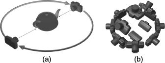
Figure 2.22 (a) This shows an object shooting scheme which consists of a camera rotating around the object and a set of light sources to provide consistent lighting conditions during shooting. (b) This shows a bubble shooting camera array whose cameras shoot outward to capture the entire world.
- Light field or lumigraph
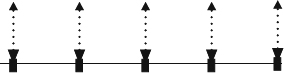
The radiance of a light ray passing through two points will be the same if there are no occlusion objects between the two points. Thus, we can enclose the objects with two planes as shown in Figure 2.23. The light ray can be expressed as (u, v, s, t). This simple representation is called a light field or lumigraph, which is a 4D simplification of the plenoptic function as described in Equation (2.5). The light field [109] and the lumigraph [110] are developed independently. Generally, the light fields are often sampled by using large camera arrays consisting of 4 × 4 or 5 × 5 cameras arranged in a simple plane. This results in a set of high resolution camera views from these cameras. Virtual views are synthesized from the parameterized representation shown in Figure 2.23 that uses coordinates of the intersection points of light rays with two known surfaces. The views in the center are interpolated linearly [109] or using the basis interpolation method [110]. This method is originally designed for capturing all lighting effects of static objects and can be easily extended to include the time dimension, which is essential for 3DTV applications by recording the videos from each camera instead of images. The most critical problem for dynamic light field methods is the large volume of data. Thus, efficient data compression is important for the success of the algorithm [111, 112]. However, the research direction in light field rendering leans toward using more sparsely arranged cameras and additional scene information, such as geometric proxies; this obviously leads to other scene representation methods.
Figure 2.23 This demonstrates the parametrization in a light field. Two planes (u, v) and (s, t) are used to parameterize all possible rays shot from the object in a space.
- Multiple view images
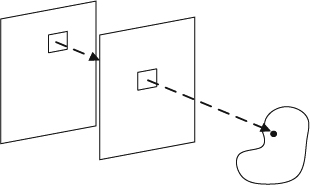
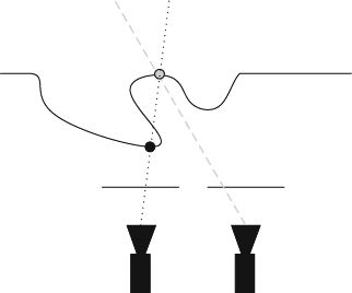
Generally a 3DTV system only provides different view directions in the horizontal direction but not in the vertical direction because of the general environment setting. Thus, the general camera is lined up along a baseline which is the line passing through all camera centers as shown in Figure 2.24. All cameras are synchronized to take the shots in videos. The videos are delivered to the receiver side. Rendering is first to position the virtual camera and project the virtual camera view in the coordinate where the original camera array takes. For the rendering of a particular display view, the closest view is selected out of the N available camera views as a first step. Then, the virtual view is synthesized from the two closest cameras by view morphing. The virtual view is then de-rectified such that it fits into the 3D display geometry again. However, using interpolation of color information from multiple views to synthesize new views results in a disocclusion recovery problem as shown in Figure 2.25. Since two views see different scene points, a point in an object observed by one camera may not be observed by another camera, which results in the occlusion of objects. In order to overcome this occlusion problem, more views must be added to remove the possibility of occlusion. Theoretically, if the number of views provided goes to infinity, the quality of the synthesized view will be improved accordingly. The main advantage of the multi-view video method is a realistic synthesized view with high quality without the need for 3D scene reconstruction. In addition, the rendering time is proportional to the number of pixels synthesized in the output images, the number of reference images, and the number of pixels from each reference image checked, and it is independent of the complexity of geometry such as primitive count in the polygonal case. This makes photorealistic rendering of a natural scene in real time possible without the need for expensive computation for rendering millions of polygons. However, this method has limitations in the possible range of changes in view direction and movement, and the quality of synthesized view depends on the number of captured views, the resolution of each view, and the scene depth variation. This leads to the need for plenty of original view images, that is, a large number of cameras has to be set up to achieve high-performance rendering, and plenty of image data needs to be processed. Therefore, conversely, if the number of cameras used is too low, interpolation and occlusion artifacts will appear in the synthesized image, possibly affecting the quality. The number of views needed to overcome the quality and occlusion problem in multi-view video methods makes the graphics community data, add some geometry information with depth data, as well as adding more flexibility in rendering and interpolation. The video-plus-depth method will be described in the next section.
Figure 2.24 A simple diagram of a line camera array. All the view directions of the cameras are parallel to each other and the camera centers are on a line.
Figure 2.25 An example of occlusion when two parallel cameras shot at the scene. The point shown in gray can be seen by the right camera but cannot be seen by the left camera.
2.3.4 Image Based Animation
Image-based representations give the reality of the world to the viewers by directly capturing the real world, but this also causes the largest limitation on dynamically animating the content. This is because, when the content in the images are shot, the lighting conditions, object relations, and other rendering conditions are fixed at that moment. Therefore, the reasonable and plausible animation to the content is to manipulate the viewing position, direction, and other viewing conditions using proper interpolation of the textures. This is because a camera is generally modeled as a point and does not affect any lighting condition, that is, changing viewing condition does not affect the content in the texture. However, even with this limitation, image-based representations can still satisfy the need for free view 3DTV systems. Interactivity for future 3DTV systems may require further interaction with the content. Generally, the interaction with the content is still difficult and therefore the main research focus is on adding virtual objects into the texture and rendering with image-based and geometry-based algorithms. The interaction and rendering technique is categorized as augmented reality. Interested readers can refer to [113] for more details.