
3.4 Multi-View System
As the autostereoscopic display provides one more successful step toward real 3D scene reconstruction, the viewers may further expect to observe motion parallax (i.e., observing scenes from different angles by changing the viewing angle). Subject to the autostereoscopic display design, the viewers will feel confused about the objects' shapes since objects are always perceived from the same angle. To realize a 3D scene reconstruction with full motion parallax support, a 3D display providing multiple views is desired. Several multi-view technologies have been developed to meet such a requirement. One realization of a multi-view system is to install a head tracking system to monitor the viewer's position and render the corresponding view on the two-view 3D display. The other realization is to develop a 3D display to show multiple views simultaneously so the viewers can watch the desired view from different viewing angles.
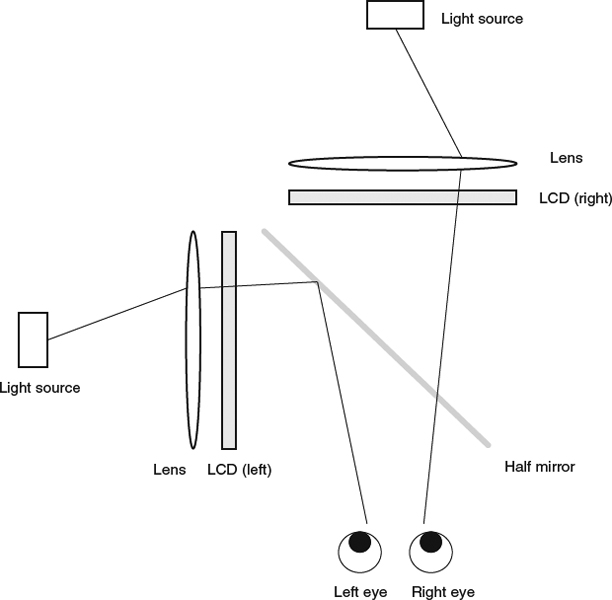
Figure 3.7 Dual-LCD 3D display.
3.4.1 Head Tracking Enabled Multi-View Display
The head tracking system can provide the viewers with geometric information related to the 3D display, such as positions and orientation, in real time. There exist many head tracking technologies, such as electromechanical, electromagnetic, acoustic tracking, inertial tracking, and optical tracking. Passive markers and active emitters/receivers are often deployed together to improve the tracking accuracy. For the applications related to 3D display, the fundamental requirement for such a tracking system is to track the center line of the face such that the display can prepare and respond to the requirements of the two eyes, one either side of the center line. Another important requirement for a 3D head tracking system is the need for a fast tracking result such that the display can have up-to-date information responding to the movement of viewers.
Having a head tracking system installed in a stereo 3D display, the 3D system is equipped with the capability to provide multi-view/look-around features. As the viewer moves around, the related position and viewing angle are calculated and the images from the corresponding view are rendered. Note that recent advanced head tracking systems can already track multiple viewers and it is feasible to provide a multi-view experience to multiple viewers simultaneously. Temporally multiplexed method with aided glasses seems to provide a straightforward way to display full-resolution pictures for each view observed by each viewer. However, to support N different views (N > 2), the hardware in both the display and glasses requires high speed operation and high video data bandwidth for N times the stereo frame refresh rate, which is often constrained by the state-of-the-art hardware technology. Therefore, the head tracking enabled multi-view 3D display is not scalable at this moment.
3.4.2 Automultiscopic
The alternative for supporting multiple users watching 3D scenes from multiple views is to extend the design principle of autostereoscopic display to the multi-view system (called automultiscopic). The practical design for the current automultiscopic display is based on the occlusion-based approach or the refraction-based approach. A four-view system is illustrated in Figure 3.8. For the parallax barrier approach, the optimal viewing distance for a N-view system is:
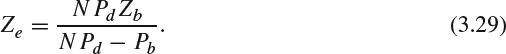
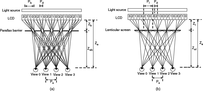
Figure 3.8 (a) Design principle of occlusion-based automultiscopic. (b) Design principle of refraction-based automultiscopic.
and the pitch of slit can be expressed as:

For the lenticular approach, the optimal viewing distance for a N-view system is:
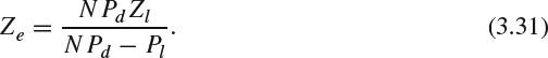
And the pitch of slit can be expressed as:
Similar to the discussion for autostereoscopic display, to support N views in the auto-multiscopic display, each view will be downsampled N times in the horizontal direction such that those N views can be presented at the existing LCD plane simultaneously. As the number of views increases, the horizontal resolution is significantly reduced. On the other hand, there is no dimension reduction along the vertical direction and thus the resolutions in horizontal and vertical directions are not balanced. Another disadvantage of this simple extension is that the black mask between LCD pixels will be viewed as black lines when viewers change their viewpoints and pseudoscopic images are observed during the viewpoint transition.
Slanted multi-view 3D display [14] is one of the technologies to resolve this unbalance issue by slightly slanting the parallax barrier or the lenticular microlens by a small degree deviated from the vertical axis of the LCD pixel panel, as shown in Figure 3.9. The subpixels belonging to each view are indicated by the region bounded by the neighboring two dashed lines shown in the figure. Having the slanted structure, the distribution of pixels in the horizontal and vertical directions will be more uniform. Besides, this new layout can alleviate the pseudoscopic problem and make the black mask less visible. In a similar way to slanting the lenticular screen, the LCD pixels can be arranged in a slanted structure to achieve the balance of horizontal and vertical resolution, though it involves significant changes during the LCD manufacturing process and makes it less practical for mass production.
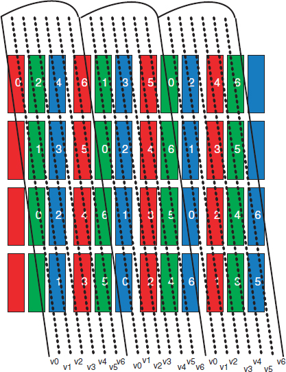
Figure 3.9 Slanted lenticular multi-view system (seven-view).
Since the automultiscopic display needs to conduct spatial subsampling to prepare the displayed pixel for each view, the display suffers from aliasing artifacts from the high frequency replica, owing to the decimation. Consequently, the high frequency component in the viewing image may be distorted. For the spatially regular subsampled layout, the anti-aliasing filter should be carefully applied after deploying the decimation so that the aliasing from the other spectrum replica can be eliminated. However, for slanted structure automultiscopic display, the pixels in each view do not form a regular 2D lattice, which causes the difficulty of applying the traditional digital filter design. Several approaches to address the irregularly spatial subsampling have been proposed to alleviate the aliasing issue. One solution is to approximate the irregular subsampling layout by a regular grid in the spatial domain and then design an anti-aliasing filter based on the regular grid structure [15]. An approximation to a regular grid can be produced by using either an orthogonal lattice, a nonorthogonal lattice, or a union-of-cosets. The selection depends on the desired tradeoff between accuracy and computation complexity. A frequency domain based solution to designing an anti-aliasing filter is proposed in [16].
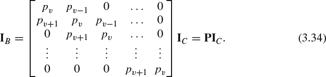
As well as the aliasing artifacts resulting from the subsampling process, automultiscopic displays also suffer from crosstalk with neighboring views. As each lenticular microlens cannot fully cover each LCD subpixel owing to the device's physical constraints, the viewer will observe light from some subpixels belonging to other views when watching one particular view. The leakage of neighboring view information will make the viewers uncomfortable, even giving them a headache. Mathematically, the crosstalk can be expressed as follows. Denote the intensity value at the j th row for each subpixel column as I(j) and the subpixel column as I = [I(0) I(1) I(2) … I(h−1)]T, where h is the number of rows in a subpixel column. As illustrated in Figure 3.9, assuming a two nearest neighbors intensity leakage model, the perceived light around subpixel location j comes from three different subpixels which are located at row j − 1 (right neighboring view), j (current view), and j+1 (left neighboring view) within the same color channel (subpixel column). Let the proportions of the received light from the current view v, right neighboring view v+1, and left neighboring view v−1 as pv, pv+1, and pv−1. And pv + pv+1 + pv−1 = 1. The perceived value, IB(j), can be expressed as follows:
To facilitate our discussion, we define the perceived subpixel column as IB = [IB(0) IB(1) IB(2) … IB(h−1)]T. Several hardware solutions – such as adding a pixel mask on the lenticular microlens display or lowering aperture ratio in parallax barrier 3D display – have been proposed to reduce crosstalk. The crosstalk can be also reduced by a software based solution, namely, a pixel value correction process, before those values are sent to the display. In [17], the value for each subpixel is corrected by taking the portion of intensity leakage from the two neighboring views into account. Let the corrected value at the j th row as IC(j) and the corrected subpixel column as IC = [IC(0) IC(1) IC(2) … IC(h−1)]T. The perceived subpixel column becomes:
To reduce the crosstalk, we can formulate the system to find the optimal corrected intensity value for each subpixel column IC such that IB is as close to I as possible. A simple solution is to formulate the problem as an unconstrained optimization problem to find the optimal corrected intensity value as follows:
We can find the optimal subpixel column ![]() via the least squared solution:
via the least squared solution:
However, given a finite bit depth for each subpixel, the numerical value for each corrected intensity value is constrained. For example, pixels with 8-bit precision should be constrained as an integer with range [0 255]. Thus, the rounding and clipping operation following the least squared solver is needed to keep the pixel value inside the valid numerical range. Therefore, the obtained solution only approximates to the optimal solution within a certain level.
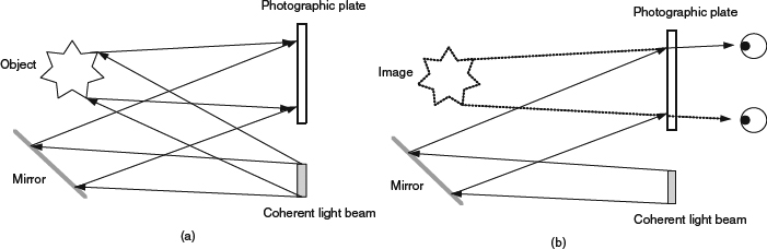
Figure 3.10 (a) Hologram recording. (b) Hologram reconstruction.