
6.4 4G Standards and Systems
The first mobile telephony systems, based on a cellular network architecture, were deployed during the 1980s. These first systems, called 1G systems as an abbreviation to “first generation”, were based on analog FDMA technology, which could only support voice services. From there, and roughly every ten years, a new generation has been deployed to provide new and improved services. As such, the 1990s saw the deployment of 2G (second generation) systems, and 3G were deployed during the first decade of the 21st century. At the time of writing, 4G systems are starting to be deployed. Each generation of mobile telephony introduces new technological innovators aimed at improving the spectrum use efficiency, access latency, communication bit rate, reliability, etc. The 2G systems introduced the use of digital wireless technology in the form of time-division multiple access (TDMA) in the GSM standard or code-division multiple access (CDMA) in the IS-95 standard. Third generation systems are best exemplified by the UMTS standard, based on wideband-CDMA technology – see Figure 6.15.
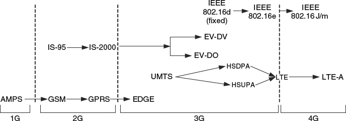
Figure 6.15 The evolution of cellular systems over different generations.
Regardless of the considered technology generation, a recurring and growing source of dissent is to what generation a standard belongs to. This has resulted in increasing lack of clarity, one that may be pointless to achieve from the technological standpoint, with some standards being labeled as “2.5G”, “3.5G”, or even “3.9G” systems. One important reason for this phenomenon is an eagerness to highlight the advances of a particular standard by classifying it into an advanced generation that the standard may not belong to from a strict technological perspective. In this book, our interest is on how recent technological advances will help communication of 3D video. Therefore, we will not delve into whether a particular standard is strictly 4G or not and we will focus on the technology in standards beyond 3G systems, which we will generically call 4G systems for simplicity. Luckily, we will be aided in this task by the fact that the 4G standards all share many similarities. Because of this, and given that, at the time of writing, LTE/LTE-A is the prevailing 4G standard we will be focusing on these standards for the rest of this chapter. As such, the goal of this section is to provide an overview of the main characteristics of LTE and LTE-A systems. Further details and a quite comprehensive treatment of this topic can be found in [9].
One important characteristic of all 4G systems is that the physical layer design is flexible enough to easily adapt the system to the different bandwidths that may be available with different spectrum allocations in different countries. Because of this, it is more appropriate to talk about the performance of the system in terms of spectral efficiency (measuring the number of bits that can be transmitted per second and per bandwidth measured in MHz), as opposed to simply considering throughput. In this sense, LTE, which is also known by its denomination within the 3rd Generation Partnership Project (3GPP) family of standards as “Release 8”, presents an improvement in cell spectral efficiency on the downlink of three to four times compared to the 3GPP Release 6 standard HSDPA, and two to three times improvement in the uplink compared to the 3GPP Release 6 standard HSUPA. This implies peak data rates of up to 100 Mbps on the downlink and up to 50 Mbps on the uplink when the system bandwidth is 20 MHz. Also, LTE is required to support a cell radius of up to 100 km and node mobility for speeds of up to 350 kph (applicable, for example, in the case of travelling in a high speed train).
The LTE standard differentiates between the services and interfaces provided to a user and the services and interfaces used for control messaging within the LTE system. For this, the “U-plane” refers to the interface (implemented through protocols) with users and the “C-plane” refers to the set of protocols implementing the interface for control messages. For access to the wireless channel through the U-plane, the LTE system aims at a latency of no more than 5 ms.
The LTE system architecture was designed with the goal of providing an infrastructure where all the information, be it delay-tolerant data or delay-sensitive interactive multimedia, is communicated as packets, using the Internet protocol (IP). The system infrastructure itself determines what are the main components of the LTE system and their interrelation. As such, the LTE system is divided into two main components:
- The evolved universal terrestrial radio access network (E-UTRAN), which is composed of the eNodeBs (or eNBs, the name given to base stations in the LTE system) and is responsible for the management of radio access and the provision of the U-plane and C-plane services.
- The evolved packet core (EPC) which is the collection of network infrastructure (hardware, protocols, services, etc.) to perform store-and-forward packet networking for mobile nodes.
6.4.1 Evolved Universal Terrestrial Radio Access Network (E-UTRAN)
The E-UTRAN implements the lowest layers of the LTE wireless networking protocol stack. At the base of the stack, it implements a physical layer that is seen from upper layers as providing physical (radio) channels. The physical layer interfaces with the MAC sublayer through “transport channels” (not to be confused with the transport layer in the protocol stack). In LTE, the MAC sublayer manages access to the wireless medium by scheduling data transmission, handling priorities and performing hybrid automatic repeat request (HARQ) functions. The MAC sublayer also manages the access to the wireless medium by mapping the transport channels, interfacing with the physical layer, with the “logical channels”. The logical channels interface the MAC sublayer with the radio link control (RLC) sublayer. On the E-UTRAN protocol stack, a packet data convergence protocol (PDCP) sublayer is found immediately above the RLC sublayer. The PDCP sublayer interfaces with the evolved packet core (EPC) component through “radio bearers”.
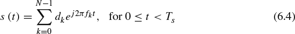
The design goal for the E-UTRAN physical layer was to provide a high performance wireless transmission scheme that could effectively address the many challenges faced with digital communication of information at high bit rate in a mobility scenario. In previous sections we discussed the nature of these challenges. Indeed, transmission at high data bit rate usually requires a signal with a bandwidth that is much larger than the channel coherence bandwidth. In this case, the channel is frequency-selective. Frequency-selective channels, or the dual time-domain effect of multipath channel delay spread, extends the duration of each transmitted pulse. When transmitting several pulses (symbols, bits) in succession, a frequency-selective channel presents the impairments of intersymbol interference, risking the introduction of detection errors at the receiver. This impairment can be addressed with different techniques. One of the most effective techniques, and the one adopted in LTE is multicarrier modulation. In multicarrier modulation, instead of transmitting a high bandwidth modulated signal, the data bits are transmitted in parallel using multiple mutually orthogonal signals of a bandwidth small enough such that the channel appears as non-frequency-selective. To see this operation, consider that multicarrier modulation is used as an alternative to the transmission of a block of N bits ![]() that are mapped to a high bandwidth modulated signal. The multicarrier modulated symbol is implemented by doing:
that are mapped to a high bandwidth modulated signal. The multicarrier modulated symbol is implemented by doing:
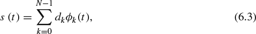
where ϕk(t) is the kth subcarrier signal used to transmit the kth data bit (a data symbol, in general). Importantly, the N subcarrier modulating signals have to be orthogonal to each other, which means that for a multicarrier modulated symbol of duration Ts the following has to be true:
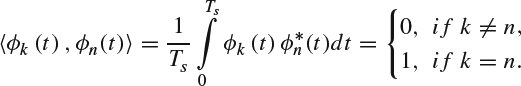
This expression assumes a complex baseband interpretation for the transmitted signal that allows for the subcarrier modulating signals to be complex valued, and thus, ![]() denotes the complex conjugate of the function ϕn(t). Note that different data bits transmitted in the multicarrier modulated symbol in (6.3) can be separated at the receiver through a matched filter type of processing, which will lead into the above implementation of integration operations testing whether the subcarrier's modulating signals are orthogonal or not.
denotes the complex conjugate of the function ϕn(t). Note that different data bits transmitted in the multicarrier modulated symbol in (6.3) can be separated at the receiver through a matched filter type of processing, which will lead into the above implementation of integration operations testing whether the subcarrier's modulating signals are orthogonal or not.
There are multiple multicarrier modulation techniques, each using a different choice of orthogonal signals. For the downlink (the transmission from the eNB to the UE) of E-UTRAN, the chosen multicarrier modulation technique was orthogonal frequency division multiplexing (OFDM). This technique is of particular importance beyond LTE because, except for different variations tailored to specific systems, it is the technique that has gained more acceptance as the modulation technique for high data rate wireless networks and 4G mobile broadband standards. In OFDM, the orthogonal signals used for multicarrier modulation are truncated complex exponentials:
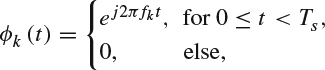
where fk = f0 + kΔf, and Δf = Ts. Because these signals are truncated complex exponential, each has a spectrum of the form sin(x)/x, where the argument x includes the shift in frequency kΔf with respect to the base frequency f0. Therefore, the OFDM symbol is:
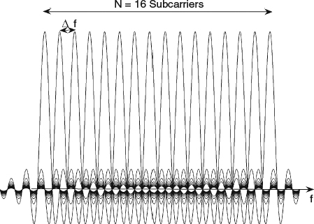
Figure 6.16 The spectrum for 16 OFDM subcarriers.
The spectrum of this symbol when dk = 1 for all input bits is shown in Figure 6.16. By setting dk = 1 for all input bits, the figure shows the contribution of each subcarrier to the overall spectrum. This contribution is a frequency-shifted function of the form sin(x)/x. The figure also illustrates how OFDM splits a carrier with large bandwidth into multiple orthogonal subcarriers of much smaller bandwidth. It is also important to note how the orthogonality property between the truncated complex exponentials forming the modulating signals can be seen in the figure, as at the central frequency of any chosen subcarrier (the frequency at which the spectrum for the subcarrier is maximum), the spectrum for all the other subcarriers is zero.
Assume, next, that the OFDM symbol in (6.4) is sampled with a period such that N samples are taken in one symbol, Tsa = Ts/N. Then, we can write the resulting sampled signal s[n], for the OFDM case, as:
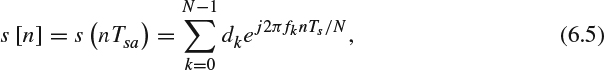
Assuming, without loss of generality, that f0 = 0 we get fk = kΔf = k/Ts, leading to (6.5) becoming:
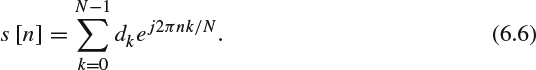
This result shows that the OFDM symbol is, in fact, a discrete-time signal s[n] formed from the inverse discrete Fourier transform (IDFT) of the sequence of input data dk. This observation will soon be seen to be the basis for one of the main advantages for OFDM because it provides a simple way of generating an OFDM symbol.
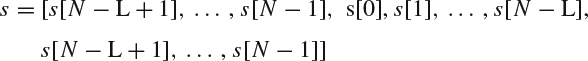
In practice, the OFDM symbol as defined in (6.5) is extended with the addition of a cyclic prefix. To understand the construction of the prefix, assume a multipath channel with L taps defined through the coefficients h[0], h[1],…, h[L − 1]. With this in mind, the original discrete-time channel input sequence (6.5) s[0], s[1],…, s[N − L], s[N − L+1],…, s[N − 1] will become s[N − L+1],…, s[N − 1], s[0], s[1],…, s[N − L], s[N − L+1],…, s[N − 1] after adding the cyclic prefix. Note that the prefix is built by just copying the last L − 1 elements of the original channel input sequence s[n] at the beginning of it. This operation does not affect the OFDM signal or its properties, such as the orthogonality between the multicarrier modulated signals, because it is simply a reaffirmation of the periodicity of the OFDM symbol. This follows from (6.6), because all sequences resulting from the discrete Fourier transform or the inverse discrete Fourier transform of another sequence are periodic with period equal to N. Also note that, following the assumption of a multipath channel with delay spread L, the samples corresponding to the cyclic prefix will be affected by intersymbol interference from the previous OFDM symbol (transmitted over the time lapse Ts ≤ t < 0). OFDM signals are particularly suitable for communication over multipath, frequency-selective wireless channels because intersymbol interference can be easily combatted by removing the prefix at the receiver without any loss of information in the original sequence and without intersymbol interference affecting the original sequence. Next, we illustrate how adding the cyclic prefix transforms a frequency-selective fading channel into a set of parallel flat fading channels.
Let us call the discrete-time channel input sequence, after adding the cyclic prefix, as s where:
The discrete-time output of the channel can be written as the convolution with channel impulse response:
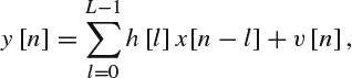
for n = 0, 1, 2, …, N + L − 1 and where v[n] is additive white Gaussian noise.
The multipath channel affects through intersymbol interference the first L − 1 symbols and therefore the receiver ignores these symbols. The received sequence is then given by:
y = [y[L], y[L + 1], …, y[N + L − 1]].
Equivalently, the repetition of the last L samples of s[n] as a prefix to this sequence introduces a symmetry into the computation of the convolution that allows us to write the received signal in terms of the original channel input as:
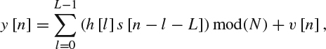
where (.)mod(N) denotes a modulo-N arithmetic operation. This can be also written in terms of cyclic convolution as:
![]()
where ⊗ denotes cyclic convolution. At the receiver, the transmitted data is extracted from the OFDM symbol by, among other operations, removing the cyclic prefix and performing a discrete Fourier transform (DFT), to counter the inverse discrete Fourier transform. The result of these operations is:
Yn = HnSn + Vn,
where Yn, Hn, Sn and Vn are the nth point of the N-point DFT of the received signal, channel response, channel input, and noise vector, respectively. The importance of this result is that it implies that at the receiver side, the frequency-selective fading channel has been transformed to a set of parallel flat fading channels.
Figure 6.17 shows a summary of the main operations involved in a communication link using OFDM as a block diagram of a transmitter and a receiver. Highlighting the main operations discussed above, an OFDM symbol is made of a block of N input symbols. At the OFDM transmitter, the N input symbols are converted into an OFDM symbol with N subcarriers through an inverse discrete Fourier transform computation. Before transmission, the OFDM symbol is completed by adding a cyclic prefix to help combat the effects of intersymbol interference introduced by the frequency-selective wireless channel. At the receiver, the originally transmitted data is recovered by performing the reverse operations to those done during transmission. This highlights the benefit when using OFDM as it implements a relatively reduced complexity technique that is effective in combating the effects of a frequency-selective channel.
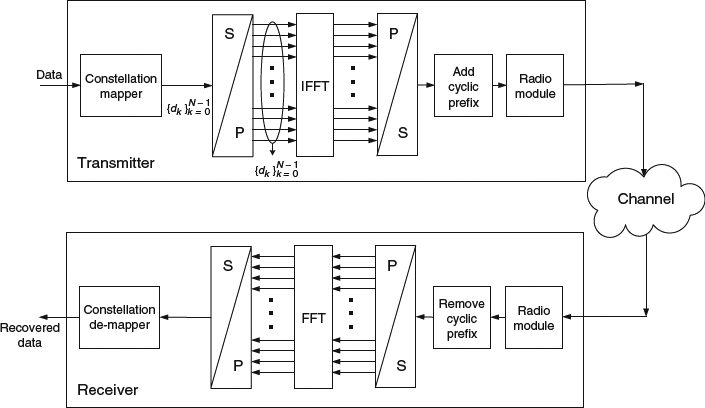
Figure 6.17 OFDM transmitter and receiver block diagram.
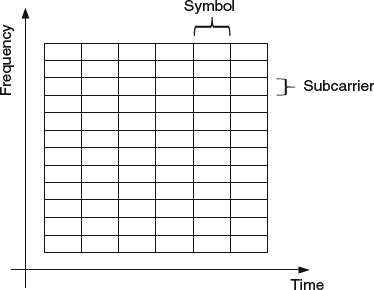
Figure 6.18 Time-frequency structure of an OFDMA frame.
Figure 6.19 LTE downlink processing.
When considering the successive transmission of several OFDM symbols, the data is organized on the channel during transmission following what can be pictured as a grid in a frequency × time plane, with a width of N subcarriers (in the frequency dimension) and a depth equal to the number of transmitted OFDM symbols (in the time dimension). This is illustrated in Figure 6.18. Also, Figure 6.19 illustrates the main processing blocks in the downlink of an LTE system.
The processing in the uplink of the LTE physical layer is very similar to the downlink, as shown in Figure 6.19. Perhaps the main difference to note is that the modulation scheme in the uplink is not OFDMA but a related modulated scheme called SC-FDMA (single carrier-frequency division multiple access). Figure 6.20 shows the processing blocks involved in SC-FDMA. By comparing the figure with Figure 6.18, it can be seen that the only difference, on the transmitter side, is the presence of a DFT block before IFFT. The operation in the DFT, essentially a linear precoding step, makes a number of continuous OFDM subcarriers (those chosen by the subcarrier mapper) appear as a single contiguous carrier. When compared to OFDM, this precoding operation results in SC-FDMA operating more on the linear performance region for the power amplifier.
6.4.2 Evolved Packet Core (EPC)
While previous generations of wireless systems necessitated an infrastructure for voice telephony services and another for packet data services, LTE is the first standard to be based on a single infrastructure carrying IP packet data. The component of the LTE infrastructure implementing most of the required functionalities for an all-IP network is the evolved packet core. Doing away with the need for a voice telephony infrastructure results in a simplified architecture for the EPC that allows reduced access latency. In the EPC it is possible to find the main elements necessary to manage IP packets, such as gateways and mobility management modules.
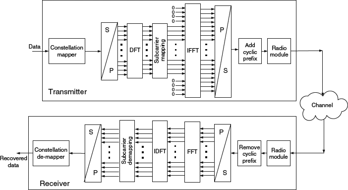
Figure 6.20 SC-FDMA transmitter and receiver block diagram.
At the EPC there are also the mechanisms necessary to manage nine different quality-of-service (QoS) class identifiers (QCI). As the name indicates, the QCIs identify each data bearer with an identifier that establishes a scheduling priority order, a packet delay budget (with possible values of 50–300ms) and a target packet error rate loss rate (with possible values of 10−2 to 10−6). This function is intended to provide support for the wide variety of traffic types that are with LTE carried using IP packets.
6.4.3 Long Term Evolution-Advance (LTE-A)
The next step of improvements on the LTE system is being incorporated into the long term evolution-advance (LTE-A) standard. Within the family of 3GPP standards, LTE-A corresponds to “Release 10” and “Release 11”. Compared with LTE, LTE-A is designed to provide significant improvements in the data communication speed and in the wireless links quality in general. For example, LTE-A aims at providing peak data rates of 1 Gbps on the downlink and 500 Mbps on the uplink and a reduced latency on the U-plane when compared to LTE.
In order to achieve the target performance improvements, LTE-A uses a number of techniques. One of these is the use of advanced network topologies that rely on highspeed, short-range base stations in the form of femtocells and also the introduction of new relay nodes. Also, LTE-A provides for carrier aggregation, where it is now possible to combine several carriers together so as to obtain a larger system bandwidth. Combined with an improved spectral efficiency, carrier aggregation allows for higher data rates. The possible schemes for carrier aggregation are very flexible, even allowing for asymmetric carrier aggregation, with higher capacity allocated to the downlink. For example, it is possible with LTE-A to aggregate, using frequency division duplexing, two 20 MHz bands for the uplink and four 20 MHz bands for the downlink, or aggregate, using time division duplexing, five 20 MHz bands that can subsequently be dynamically allocated between uplink and downlink, using the flexibility provided by the time division duplexing scheme. Also, LTE-A introduces mechanisms that allow various eNBs (base stations in the 3GPP terminology) to collaborate during both transmission and reception of signals. For example, several eNBs can leverage a high speed wireline backhaul connection to implement a distributed beamforming transmission scheme. These techniques have been called “coordinated multipoint” (CoMP) transmission and reception.
6.4.4 IEEE 802.16 – WiMAX
IEEE 802.16 is a family of standards developed under the guidance of IEEE's 802 Standards Committee to provide broadband wireless access capabilities. The standard has been evolving with different variations and updates since the early 2000s and includes variants for both fixed and mobile broadband wireless access. The name “WiMAX”, or “worldwide interoperability for microwave access”, was introduced by the WiMAX forum, which is an industry alliance created in 2001 to promote 802.16 and certify that products for the standard are compatible.
Because the IEEE 802.16 standard has been evolving for several years and presents variants for mobile and fixed broadband access, different elements of the standards may present some variations. Nevertheless, in a broad view, it can be said that the IEEE 802.16 standard shares numerous common or similar design elements with other 4G cellular systems and, as a matter of fact, pioneer some of them. Specifically, the physical layer for the fixed broadband version, IEEE 802.16d, uses OFDM with a fixed number of 256 subcarriers. In the case of the mobile version, IEEE 802.16e, OFDM is still used but the fixed number of subcarriers was changed to give the possibility of having a variable number. This allows a flexible support of different channel bandwidths from 1.25 MHz to 20 MHz and up to 2048 subcarriers. As with all modern communications standards, WiMAX supports adaptive modulation and coding (AMC) that allows to choose between 64QAM, 16QAM, QPSK, and BPSK as modulation options. The standard also includes provisions for the use of multiple-input, multiple-output (MIMO) antenna technology.
WiMAX also supports different classes of services, which are used to provide the QoS required by different types of applications. Specifically, there are five different classes of services: “unsolicited grant service” which can be used for the transport of real-time fixed-size packets as is done over T1 or E1 digital lines; “extended real-time polling service”, which provides the type of QoS needed by real-time variable-sized packets; “real-time polling service”, which is applicable to streams generating periodic variable-size packets at periodic intervals; “non-real-time polling service”, which, as the name indicates, is for delay-tolerant variable-size data packets that needs to be transmitted at a minimum data rate; and finally a “best effort” type of service. These classes of service are useful for the scheduler to perform subcarrier allocation in an OFDM frame among different requesting services.
It is worth noticing that while the 802.16e standard was designed to provide mobile broadband data access, certain features in the standard, such as the provisions for channel estimation, do not perform as well in a high mobility scenario as those found in standards such as LTE. Consequently, WiMAX has seen a more limited adoption from cellular carriers operators. Finally, the interested reader should note that further details and a quite comprehensive treatment of WiMAX can be found in [10].
More recently, the IEEE 802.16e standard has evolved into the IEEE 802.16m standard, sometimes called the “next-generation mobile WiMAX” or “WiMAX 2”, [11]. While the IEEE 802.16e standard is often considered to still be pre-4G (see Figure 6.15), and sometimes is even classified as a “3.9G” standard, the evolved IEEE 802.16m aims at reaching data transfer rates of more than 1 Gbps and support for a wide variety of all-IP services, making it a true 4G standard comparable with LTE-A. At the same time, IEEE 802.16m maintains backward compatibility with previous versions of the WiMAX standard. Some of the improvements incorporated in IEEE 802.16m include explicit protocol design consideration for operation using relay stations, improved MIMO-operation modes and the ability to control and operate over several carriers at the same time by introducing the possibility for a single MAC layer to simultaneously control multiple physical layers. At the same time, backwards compatibility with the previous IEEE 802.16 version leads toward maintaining the use of OFDM and adaptive modulation and coding.