
8.3 Error Concealment
There are numerous techniques with the goal of preventing the occurrence of channel-induced errors, reducing the sensitivity of the compressed video stream to these errors, or recovering from errors, but the reality is that errors will eventually be introduced by channel impairments. This section discusses techniques that allow the decoder to conceal and limit the effects of these errors on the reconstructed video.
The general idea for error concealment is to replace part of a missing frame with an estimate of it. This involves using other parts of the video sequence that are correlated with the missing one and possibly combining it with other available information so as to obtain the best possible estimate for replacing the missing part of the video. Figure 8.9 illustrates what is perhaps the best case scenario for error concealment in legacy single-view video. In this example, two macroblocks of a frame have errors after decoding and need to be discarded. Fortunately, we assume that the motion vectors for the frame with errors and the previous frame are received with no errors. In this case, the discarded macroblocks can be replaced by using the correctly received motion vectors to estimate the lost macroblocks by doing motion compensation from the previous frame.
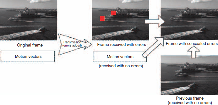
Figure 8.9 Illustration of error concealment in legacy single-view video, replacing lost macroblocks with the motion-compensated macroblocks from the previous frame received with no errors.
Multi-view video offers more options for correlated information that can be used to do error concealment. In addition to the possibilities already present in single-view video, using spatial and temporal correlation plus motion vector information, multi-view video also offers the disparity correlation between different views. However, having more options presents the challenge of choosing the best one. That is, one problem of interest with multi-view error concealment is what received data that is correlated with the lost information to use to achieve the best error concealment results. This problem is addressed in [6] by presenting the following simple procedure:
(a) Denote as l1, l2,…, lL the lost macroblocks in a frame from view v at time index n.
(b) Denote as p1, p2,…, pL the macroblocks in the same spatial position in the frame from view v at time index n − 1.
(c) Denote as s1, s2,…, sL the macroblocks in the same spatial position in the frame from view v at time index n − 2.
(d) Denote as m1, m2,…, mL the macroblocks in the same spatial position in the frame from view w at time index n − 1.
(e) Calculate

where Δpsi is the squared differences between the pixels in macroblocks pi and si.
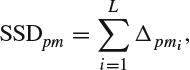
where Δpmi is the squared differences between the pixels in macroblocks pi and mi.
(g) Evaluate whether SSDps ≤ SSDpm, in which case the macroblocks l1, l2,…, lL are replaced by p1, p2, …, pL.
(h) When SSDps > SSDpm the macroblocks l1, l2,…, lL are replaced by m 1, m2,…, mL.
In most 3D video compression algorithms one of the views is encoded as a single-view video sequence, that is, using temporal motion compensation, while the other view is encoded using both temporal motion compensation and other-view disparity differential encoding. Then, while the first view does not depend on another view for encoding and decoding, the second view does. This is a key difference that influences how error concealment can be implemented. This issue is addressed in [7]. In this work, it was assumed that the left view is encoded using only temporal motion compensation and that the right view is encoded using both temporal motion compensation and disparity differential encoding with respect to the left view.
The first error concealment case studied in [7] is when the right view is received with errors and the left view is received correctly. Here, the problem may have two stages. The first part of the problem is how to replace motion and disparity vectors if they had been lost due to channel-introduced errors. If this is the case, the motion and disparity vectors are replaced by selecting candidate replacement vectors as those that had been correctly received and are from regions in the affected frame that neighbor the area where the information was lost. Each candidate replacement vector has associated a possible replacing macroblock from the reference frame from which the vector is derived and that can be used for error concealment. The next task is to select one replacement macroblock. This is accomplished by choosing the candidate replacement macroblock with the minimum absolute difference between the external boundary of the lost macroblock in the current frame and the internal boundary of the replacing macroblock in the reference frame.
Nevertheless, the presentation in [7] successfully argues against performing error concealment by simply replacing one lost macroblock with another macroblock (this is, in fact, the simple idea illustrated in Figure 8.9). This is because the effects of motion or view disparity do not affect all pixels in a macroblock in the same way. With this observation in mind, the improvement proposed in [7] is based on an “overlapped block motion and disparity compensation” (OBMDC) operation that replaces each pixel in the lost macroblock with a weighted combination of pixels in the same location but from more than one replacement macroblock, using the expression:

where plost(x, y) is the new replacement pixel at coordinates (x, y), p*(x, y) is the pixel at the same coordinates associated with the previously selected best vector (that is, the pixel that belongs to the macroblock with the minimum absolute difference between the external boundary of the lost macroblock in the current frame and the internal boundary of the replacing macroblock in the reference frame), pcndt(x, y) is a pixel from one of the other candidate macroblocks (which was not selected as best), v refers to pixels in the same view as the one with errors, ![]() refers to the other view, and w1, w2, and w3 are the weights chosen so that w1 > w2 > w3. Note that the choice w1 > w2 > w3 implies that the previously chosen best macroblock still retains a higher weight, followed by macroblocks in the same block and lastly macroblocks in the other view. In [7], w1, w2, and w3 are chosen equal to 5, 4, and 3, respectively.
refers to the other view, and w1, w2, and w3 are the weights chosen so that w1 > w2 > w3. Note that the choice w1 > w2 > w3 implies that the previously chosen best macroblock still retains a higher weight, followed by macroblocks in the same block and lastly macroblocks in the other view. In [7], w1, w2, and w3 are chosen equal to 5, 4, and 3, respectively.
Recall next that in [7] it is assumed that the left view acts as reference for encoding the right view using disparity differential encoding. As a consequence, the presence of lost or discarded macroblocks in the left view adds the challenge of error propagation in the right view also. In [7], it is argued that the best approach to tackling this issue is to perform error concealment on the left view and then decode the right view using the concealed macroblocks from the left view.
In addition to losses at the level of a number of macroblocks, it is possible that channel impairments may lead toward the loss of a frame. In this case, it is necessary to apply error concealment techniques at the frame level. In [8] the problem is approached for a 3D video compressor that encodes the information into a color and a depth component. For the purpose of implementing the error concealment technique, the encoder is modified to operate using a “shared motion vectors” mode. This mode, which in fact can be considered an instance of error resilience encoding, does motion estimation and calculation of motion vectors only for the color component of the encoded video. The resulting motion vectors are used of course to encode the color information but they are also used to encode the depth information. With this configuration, when a color frame is lost, the motion vectors can be recovered and the lost frame concealed by using a correctly received depth frame. Conversely, when a depth frame is lost, it can be concealed by using the received shared motion vectors and a correctly received corresponding color frame. The results presented in [8] show that the use of shared motion vectors has a relatively small impact on the source encoder coding efficiency since it introduces a penalty of around 1 dB in the PSNR. At the same time, the resulting frame loss concealment scheme has a performance of 3 dB or better for most operating conditions when compared to a frame replacement solution.
For the case of multi-view video sequences, [9] discusses three different error concealment techniques and a method to choose the best one to use. The first technique, identified as “temporal bilateral error concealment” (TBEC) uses a temporally correlated previous and subsequent frame to estimate the motion vector. By assuming that the motion vector in the video was constant during the time elapsed between the previous and the subsequent frame, the motion vector is estimated to be equal to that derived from the motion estimation using the previous and subsequent frames. Having estimated a motion vector, the concealed pixel is the average between the motion compensated pixels in the previous and subsequent frames. Note that the main limitation of this scheme is the assumption that the motion vector stays invariant in the time elapsed between the previous and subsequent frames. Consequently, this error concealment technique will perform better, the less motion is present in the video sequence.
The TBEC error concealment technique can be further extended to the particular correlated information offered by multi-view video. This technique, called “inter-view bilateral error concealment” (IBEC) estimates the disparity vector by using the view to the left and to the right of the one to be concealed. The technique is based on the assumption that the cameras for each view are located in a parallel configuration, with the objects in the video at a sufficient distance that the disparity vectors can be assumed constant between the views to the left and to the right of the one to be error-concealed. With this assumption, the disparity vector is estimated to be equal to the disparity vector derived from the disparity estimation using the views to the left and to the right. Having estimated a disparity vector, the concealed pixel is the average between the disparity-compensated pixels from the views to the left and to the right. Note that the main limitation of this scheme is the assumption that the disparity vector stays invariant between the views to the left and to the right. As such, this technique does not work well when there are objects that are occluded in some of the three views being considered and not in the rest.
The third error concealment technique, discussed in [9], is called “multi-hypothesis error concealment” (MHEC), and is reminiscent of the scheme discussed above from [7] where candidate replacement vectors are selected from those that had been correctly received and are from the same regions in the affected frame. In the case of I-views and P-views, the candidate vectors are those from the previous and subsequent frames, and in the case of B-views the candidate vectors are selected also from the previous and subsequent frames and, in addition, the views to the left and to the right of the one that is the target for concealment. Each candidate replacement vector has associated a possible replacing block from the reference frame from which the vector is derived and that can be used for error concealment. In the MHEC technique, the candidate replacement blocks with the two smallest sum of absolute differences (SAD) are used to replace the lost block using the relation:
B = wB1 + (1 − w)B2,
where B is the replacement block, B1 is the candidate block with the smallest SAD, B2 is the candidate block with the second smallest SAD and w is the applied weight (with possible values between 0 and 1) which was chosen equal to 2/3. In the case of this error concealment technique, it is necessary to bear in mind that the selection of the two best replacement blocks becomes unreliable when the reference frames have different motions or disparities.
From the above discussion, it is possible to see that the three techniques discussed in [9] follow well-established principles but also are limited in their performance under some operating conditions. Consequently, the last challenge to address in the error concealment technique in [9] is which of the three error concealment techniques to use in each case. This is decided by computing for each of the three techniques the cost function:
![]()
where λ is a weighting factor and x1 and x2 are, respectively, the motion vector and the negative of the motion vector used in TBEC, the disparity vector and the negative of the disparity vector used in IBEC, and the blocks B1 and B2 for the MHEC technique. Once the cost function has been computed for the three techniques, the one with lowest result is the one chosen.