
Multiple Rendering Passes
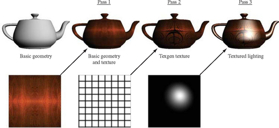
One of the most powerful features of the OpenGL pipeline is the ability to render a primitive multiple times using different modes, combining the results together to produce the final image (Figure 9.1). This approach implements the equation Ifinal = I1op1 I2 op2 … In, where opi represents an arbitrary combining operation. In essence, a multipass approach combines the individual functional elements of OpenGL into a programming language, increasing the power and generality of the implementation. An application can do more computations than can be performed in OpenGL during a single pass over each primitive, and can achieve a wide variety of additional effects.
Using multiple rendering passes to draw a single frame can significantly impact rendering performance, which can lead to unacceptable frame rates. As the raw performance of graphics hardware improves, however, applications can budget multiple rendering passes to increase the frame quality, yet still maintain their desired frame rate. Investing computation time on multipass algorithms can often yield more improvement to image quality than applying it to increasing polygon counts. Many of the algorithms described in the remainder of the book use multiple rendering passes to implement algorithms; becoming familiar with these basic multipass principles provides the framework for modifying and extending them.
9.1 Invariance
Section 6.1.1 describes the concept of invariance and how it applies to rasterization operations. The invariance rules are vital to ensure correct multipass rendering; without invariance there is no guarantee that a given primitive, re-rendered with different attributes by a multipass algorithm, will render predictably and generate the desired result. Application writers should be aware that sometimes the OpenGL invariance rules can be subtle.
For example, a primitive doesn’t have to produce the same fragments if blending is enabled and disabled, but it must do so if blending is effectively disabled by setting the source and destination blend factors to GL_ONE and GL_ZERO. Since the invariance rules allow for a lot of diversity between implementations, many vendor’s implementations may be invariant even when a feature such as blending is explicitly enabled or disabled. While convenient, this additional implementation-dependent invariance can lure application writers into believing that this is the case for all implementations.
Table 9.1 lists methods for effectively disabling a particular feature that still maintains invariance. These methods are guaranteed by the OpenGL specification; they should work on any compliant implementation.
Table 9.1
Disabling Operations while Maintaining Invariance
| State Enable | Function | Disable Arguments |
| GL_POLYGON_OFFSET_POINT | glPolygonOffset | factor = 0.0 |
| GL_POLYGON_OFFSET_LINE | units = 0.0 | |
| GL_POLYGON_OFFSET_FILL | ||
| GL_SCISSOR_TEST | glScissor | x = 0 |
| y = 0 | ||
| width = window width | ||
| height = window height | ||
| GL_ALPHA_TEST | glAlphaFunc | func = GL_ALWAYS |
| GL_DEPTH_TEST | glDepthFunc | func = GL_ALWAYS |
| GL_STENCIL_TEST | glStencilOp | zfail = GL_KEEP |
| zpass = GL_KEEP | ||
| glStencilFunc | func = GL_ALWAYS | |
| GL_COLOR_LOGIC_OP | glLogicOp | opcode = GL_COPY |
| GL_INDEX_LOGIC_OP | ||
| GL_BLEND | sfactor = GL_ONE | |
| dfactor = GL_ZERO |
9.2 Multipass Overview
Each stage of a multipass algorithm splits into two steps: how to render one or more primitives, and how the resulting image should be merged with the image from previous steps. Care must be taken at each step, not only to ensure that the desired effect was achieved, but also to ensure that all the buffers affected by this step contain the proper values for the operations that follow.
A simple example that illustrates what must be considered when constructing multipass techniques is an implementation of separate specular color functionality. The separate specular color is part of core OpenGL 1.2; it is described in Section 3.3.4.
The multipass implementation of this lighting mode requires two passes. In the first pass, primitives are rendered with vertex lighting enabled, but with the material’s specular reflectance set to zero. Zeroing the material specular component ensures that the color from this pass doesn’t include a specular contribution. In the second pass, the primitives are re-rendered, this time with the ambient, diffuse, and emissive reflectances set to zero, and the specular reflectance set to the desired value. The result is two separate renderings of the primitive; one with primary (diffuse), one with secondary (specular) colors.
In the specification of separate specular color, OpenGL computes the secondary color separately, then adds it to the the fragment color after texturing. Since the secondary color isn’t modified by texturing, our multipass algorithm can duplicate this algorithm by disabling texturing during the second rendering pass. Adding together the primary and secondary light contributions can be done with blending. Blending is enabled during the second pass, with both the source and destination blend factors set to GL_ONE.
This blending equation causes the fragment colors from the two computations to be added together in the framebuffer. When blending two separate renderings of an object, there are several details that must be considered. If depth testing is enabled for both passes, the default depth function, GL_LESS, discards all of the fragments from the second pass before blending. Changing the depth function to GL_EQUAL results in better behavior, since fragments from the second pass with depth values equal to the visible fragments of the first pass now pass the depth test and are blended.
For most situations this method is sufficient. If the rendered geometry is not well behaved, however, multiple fragments might be rasterized to the same depth value as the visible pixel. This effect would be invisible when blending isn’t enabled, but in this case the extra fragments will be included in the blending computation, generating undesirable artifacts. One way around this problem is to render each image separately without blending, trim to the geometry of interest (with stencil, for example), then blend the color images in a separate step. In general, the complexity of the merge step can vary, depending on details of the scene, the image quality required, and how the application will use the modified buffers after the algorithm is finished.
To illustrate these trade-offs, consider the separate specular color example in more detail. Care should be taken if the alpha component of the lighted polygon will be used later by the application (for example, if the lighted geometry is being alpha tested or a framebuffer containing alpha components is used to store the alpha components of the pixels for use later on). There are some subtleties here; regular vertex lighting (and therefore OpenGL’s separate specular color method) uses the alpha from the diffuse material as the final alpha component of the lighted primitive; the alpha components of the ambient, emissive, and specular reflectance are not used.
If the algorithm must compute the final alpha components correctly, we should consider how these alpha values may be used. The requirement may be that only the final alpha values stored in the framebuffer image must be correct. This could be done by rendering the first, diffuse pass of the algorithm with the diffuse alpha components, and using alpha values of zero for the second, specular pass. However, this approach doesn’t work if the application is using alpha testing while the specular primitives are being rendered. The specular components won’t have the correct alpha components, and the specular highlights may be masked incorrectly by the alpha test.
To get both the correct final alpha values and the correct alpha test behavior, we need to render both passes using the diffuse alpha components. If this is all we did, we would get incorrect alpha values in the framebuffer; the blend equation we’re using would add together the diffuse alpha values from both passes, doubling them. This can be fixed by discarding the alpha component of the second blending pass with the glColorMask(1,1,1,0). The first pass uses the diffuse alphas, producing proper alpha test results, and updating the framebuffer with the proper alpha values. The second pass would also be using the right alpha values, so the alpha test results for the specular part of the image would be correct. The alpha results from this pass would be doubled by the blend, but then discarded by the color mask, leaving the proper alpha components in the framebuffer.
So far, we have focused on creating the proper image in the color buffer. The color buffer is a common target for multipass techniques, but not the only one. In some cases the desired result of a rendering pass is not an updated color buffer, but changes in one or more of the ancillary buffers: depth, stencil, or accumulation. These buffers may be updated directly, or as a side effect of one or more multipass operations. For example, updating the depth or stencil buffer is usually done as a side effect of rendering geometry. Getting the final values of these buffers right (if they will be needed later) is part of the algorithm design process.
9.3 The Multipass Toolbox
As the previous example illustrates, designing a good multipass algorithm requires attention to detail. But there is a more general framework that can be used to guide multipass algorithm design. Here we provide a “toolbox” of building blocks within a programming paradigm that is applicable to a wide range of algorithms.
A rendering algorithm or technique can be thought of as a specialized type of computer algorithm. They can be expressed as a programming language, containing data manipulation operations such as variable assignment, arithmetic and logic operations, and control flow constructs such as loops and conditionals. The operations available in the OpenGL pipeline itself can be mapped into constructs found in programming languages. This language can then be used to express rendering algorithms. From this more general view of OpenGL, it becomes an easier task to map a rendering algorithm into a sequence of OpenGL pipeline operations.
9.3.1 Arithmetic Operations
At every stage of the OpenGL pipeline some form of computation is performed. A few of these stages can be controlled enough by applications so that general arithmetic operations can be performed. In the two-pass specular lighting example, the arithmetic operations available through blending were used. Using OpenGL 1.3 as a reference, the blending functions provide operators for multiplication, addition, subtraction, minimum, and maximum. The constant blending function in the ARB imaging subset provides efficient operators for adding, subtracting, and multiplying by a constant. The logic op function supplies bit-wise logical operations.
There are two difficulties with color buffer blending; the values are restricted to the [0,1] range and the color precision available for each color component may be limited. The use of scaled and biased arithmetic to work around the range limitation is described in Section 3.4.1. The accumulation buffer also allows some arithmetic operations to be performed with increased range and precision. The accumulation buffer doesn’t support multiplication of a pixel color by another pixel color, but it does support multiplication by a constant. A disadvantage of the accumulation buffer is that it is not hardware accelerated on some commodity hardware. Ultimately, this problem is solved on new implementations that support floating-point operations and programmable pipeline processing, but for implementations without such support the problem is still cumbersome.
As OpenGL and hardware accelerators have evolved, the texture environment stage has become increasingly sophisticated. With the advent of multitexture’s new texture environment functions, many of the operators available for color buffer blending are also available in texture environment functionality. OpenGL 1.3 provides important new texture environment functionality: the texture environment function GL_COMBINE is a generalization of texture environment functions, such as GL_MODULATE or GL_ADD.
The GL_COMBINE function supplies an orthogonal set of operations and sources for texture functions. Sources, operators, and texgen functions can be selected separately to provide a more orthogonal mix of possible texgen operations. RGB and alpha color sources, operations, and texgen functions can be selected separately. Functionality in the texgen stage of the OpenGL pipeline is important because of multitexturing. If the implementation supports multitexturing, chains of arithmetic operations can be performed in a single pass, which can produce higher quality images and significant performance gains. The implications of multitexturing are described in more detail in Section 9.5.1, later in this chapter.
The GL_DOT3_RGB and GL_DOT3_RGBA texture environment functions go beyond blending functionality by introducing dot product operations to the list of combine operations. Two types of dot products can be generated from a pair of color values; one operates on RGB, the other on RGBA. As with the other GL_COMBINE functions, the alpha value can be processed separately. See Section 5.10.1 for more details on texenv functionality.
If the OpenGL implementation supports the ARB imaging subset, some additional powerful operators become available to the application. The color matrix function can be used to perform affine operations on the components of a pixel, including swizzling components from one channel to another. For example, the following matrix swaps the R and G channels in an image:
Note that this functionality is only available when loading or reading images or texture maps. The highest performance path that provides pixel operations is usually glCopyTexImage2D and glCopyPixels, since they don’t read or write pixels to system memory.
9.3.2 Arbitrary Functions
Notably missing from the standard arithmetic operators is division. Division can be emulated to some degree by multiplying by the reciprocal of the divisor. One advantage of using reciprocals is that the reciprocal often fits within the [0,1] range constraint for color and texture components. Going beyond division, it is also often desirable to apply other functions such as sine, cosine, and so on.
One way to efficiently approximate arbitrary functions is to implement them as lookup tables. OpenGL provides several types of lookup tables: pixel maps, color tables, and texture maps. Pixel maps and color tables provide a way to map an input color value to an output color value; in other words, evaluate y = f(x), where the domain and the range of f are constrained to [0, 1].
Texture maps can be treated in a similar way, except that 1-, 2-, and 3-input functions can be implemented using 1-, 2-, and 3-D texture maps. The difficulty comes in providing a more flexible way to provide input values: we would like to provide greater control over the texture coordinate values used to index the texture maps. Texture coordinates can be supplied as vertex parameters, generated automatically, and transformed using the texture matrix. This makes it possible to use simple functions of the object or eye space x, y, or z values, but makes it difficult to use the results of arithmetic operations on individual pixels as the input to these functions.
The SGIS_pixel_texture extension solves this problem by providing a means to interpret color values in pixel images as texture coordinates. Using SGIS_pixel_texture, the first pass of an algorithm can generate an image I, and then the resulting image can be copied over itself using glCopyPixels with texturing enabled to compute f(I). The ARB_fragment_program extension also provides this functionality, sometimes called dependent texturing, as part of a programmable texturing interface. See Section 5.10.2 for more details on programmable texturing.
Using texel values to index into other textures doesn’t have to be enormously expensive. If pixel colors are stored in the color buffer using 8-bit components, then the texture memory requirements are modest for 1D and 2D functions, needing only 256 × 1 and 256 × 256 texture maps.
9.3.3 Conditionals
The OpenGL pipeline performs conditional or selection operations at a number of stages in the pipeline. One or more of these stages can be used together to implement simple conditional operations in a multipass algorithm. Examples include the depth and alpha tests. Alpha test performs per-fragment comparisons against a reference value and rejects the fragments that fail the test. Even though the test only examines the alpha value, it can be made more general by using other OpenGL operators to map RGBA colors that need testing to specific alpha values. For example, to reject pixels that have 0 for both the R and G components, use the color matrix to put the sum of R + G in the A component and reject pixels with A = 0.
Using the stencil and depth buffer together provides powerful conditional logic. Simple arithmetic and logical operations such as counting and exclusive-or, can be performed in the stencil buffer and the result used to selectively update the color buffer. Additional blending functions such min/max and constant factors are also useful accelerators for conditional logic. Logic operations (expanded to include RGBA support in OpenGL 1.1) provide a large set of bitwise boolean operators, including AND, OR, XOR, COPY, SET, and inverted versions of these operations.
Conditional tests in earlier stages of the pipeline may prove useful as well. Culling and clipping operations use the value of vertices to reject all or part of a primitive. With appropriate transformation matrices, these tests can be used to reject primitives subject to more complex conditions than ‘inside’ or ‘outside’ the viewing frustum. For example, the diffuse and specular terms of the lighting equation are clamped to zero if the surface normal points away from the light source. The resulting color can be used as a flag that can be tested in later parts of the pipeline.
These examples may seem odd or even absurd; after all, OpenGL isn’t a general purpose programming language. But our intent isn’t to promote obfuscated or general purpose programming with OpenGL. Instead the goal is to consider various parts of the pipeline and think of them as building blocks for multipass algorithms. We are using OpenGL functionality in a more general way, being true to the spirit of OpenGL as a graphics assembly language. We don’t have to limit the use of a pipeline feature to the specific intent or algorithms the OpenGL designers may have had in mind.
9.3.4 Variables
Early on in the evolution of OpenGL, it became clear that it was useful to have additional color buffers to temporarily hold parts of an image or scene. When constructing multipass algorithms, these temporary buffers play a role analogous to temporary variables in regular programming languages, since they both hold intermediate results. To store a result, the application could copy the contents of the color buffer to system memory until it is needed again. But the performance of an algorithm using this approach would suffer. It is usually much faster if the temporary results are stored in buffers managed by the graphics accelerator. For applications that can tolerate some visual distractions, both the front and back buffers of a double-buffered window can be used. Double-buffered stereo windows (also called quad-buffered) provide 4 buffers, but at the time of this writing, implementations that accelerate double-buffered stereo windows are not common. OpenGL defines additional color buffers called auxiliary or aux buffers, but again very few accelerators support these. One difficulty with quad buffers and aux buffers is that they are constrained to be the same dimensions as the window, whereas the application may need either a smaller or larger buffer.
One straightforward solution to the problem is to use texture memory for temporary buffers. The glCopyTexImage2D command added in OpenGL 1.1 provides an efficient mechanism to copy the results of a computation to texture memory. The temporary value can be “read” by drawing a textured quadrilateral with texture coordinates spanning the texture, using the GL_REPLACE texture environment.
Though using textures as variable storage is a good general solution, there is another more attractive location—off-screen memory. Even though off-screen memory (we will use the term drawables) may share the same location as texture memory in some accelerator implementations, there are still compelling reasons to expose it as a window-like resource: drawables can have ancillary buffers such as depth and stencil, their dimensions are not constrained to be a power of two, and they can be shared between multiple applications more easily than textures.1 In GLX and WGL OpenGL specifications, these off-screen drawables are called pixel buffers, or pbuffers for short. They are similar to aux buffers, in that they are off-screen memory, but unlike aux buffers, their access is accelerated by the graphics hardware. For more information on pbuffers see Section 7.4.1.
9.3.5 Parameters
We can further augment the multipass paradigm by adding the notion of parameters. Just as the parameters of a function call supply input to the body of the function, multipass parameters supply data that a multipass algorithm uses as input. The most obvious source of input data is the geometry’s vertex data and texture images supplied to the pixel pipeline. Vertex position, normal direction, and color can all be used to supply data to the pipeline executing a multipass algorithm. A problem may arise however: sometimes an important input parameter, such as the normal vector for surface orientation, is discarded early in the OpenGL pipeline but is needed by the algorithm in a later pipeline stage. The general solution to this problem is simple; an input parameter can always be computed in the application and sent down as a color or texture coordinate in order to reach later pipeline stages.
However, this solution may lead to large amounts of computation being performed on the host, or result in expensive pixel reads and writes to host memory. A better solution is to use OpenGL to map the desired parameters into texture coordinates. OpenGL supports a number of ways to convert vertex positions and normals into texture coordinates. Useful conversions include object or eye-space coordinates mapped to texture coordinates or fragment colors; object- or eye-space normals mapped to texture coordinates; eye reflection vector, light position, or light reflection vector, etc. mapped to texture coordinates. Details on performing these conversions to make parameters available to later pipeline stages are described below.
Vertex Coordinates Object coordinates enter the pipeline optionally with colors, texture coordinates, and normals. Vertex coordinates may be mapped to texture coordinates using texture-coordinate generation. Both object-space and eye-space coordinates are available; it can be useful to use the latter to take advantage of the transforms available with the modelview matrix. To avoid clamping, coordinates need to be scaled and biased into the standard [0,1] texture coordinate range by either folding the scaling operation into the texture-generation equations, or by using the texture transform matrix. The texture matrix may also be used to project the generated texture coordinates into two dimensions.
Mapping vertex coordinates to texture coordinates is a good way to generate distance parameters. Such parameters include distance from the viewer, distance from a light source, distances between objects, and so forth.
Vertex Normals Vertex normal vectors are discarded too early in the pipeline to be useful in many algorithms. Normals can be converted into texture coordinates within the application by issuing them directly as texture coordinates or as vertex coordinates transformed by a texgen function. Normals issued as vertex coordinates will be transformed by the modelview matrix directly, rather than the adjoint transpose of the modelview as a normal vector would be (see Section 2.3 for details).
The texture transform matrix can be used to apply a corrective transformation to normal vectors processed as vertex, then texture values. A texture coordinate standing in for a normal will have its components linearly interpolated during rasterization. This isn’t the correct way to interpolate normals, but the discrepancy may be acceptable if the surface triangles are small. Another approach is to apply a mapping function using a texture map operation to create a more accurate interpolation.
OpenGL 1.3 includes a more direct solution, the texture coordinate generation function GL_NORMAL_MAP. This function uses the eye-coordinate normal vectors as the texture coordinates. Again scaling and biasing using the texture matrix are necessary to compress the range to [0, 1]. If the values should be in the range [−1, 1], indexing a cube map with the generated texture coordinates may be a better solution. It will use all three texture coordinates to choose a cube map face and location within that face. It is a good solution if the length of the normal is not important.
Eye Reflection Vector If the eye-space reflection vector is needed, sphere map texture generation can be used to capture it as a set of texture coordinates. The sphere map texture generation computes an eye-space reflection vector and projects it to a set of 2D texture coordinates.
Again, after noting the usefulness of the reflection vector, OpenGL 1.3 also provides a more direct solution via the GL_REFLECTION_MAP texture coordinate generation function. As with normals, indexing with a cube map makes it possible to use all three direction components.
Light Position Light position or direction information is frequently used in illumination model computations (see Section 3.3). To perform similar types of computations, using a light position in other parts of the vertex processing or fragment processing pipeline may be necessary. For example, N · L may be computed as part of texture-coordinate processing in the geometry pipeline. This can be accomplished by copying the vertex normals into texture coordinates, and storing the light direction in the first row of the texture matrix, such that
the resulting transform will compute the dot product of N and L and store the result in s′. Similarly, the light vector may be used in color computations. This can be done, for example, using the dot product texture environment function.
9.4 Multipass Limitations
Using multiple passes to implement rendering algorithms provides a very general way to enhance the set of operations in the OpenGL pipeline. This process does incur performance overhead; each pass requires re-issuing and re-rasterizing the object geometry. If interactivity is an objective, then the amount of time available for rendering a frame at the desired refresh rate places an upper bound on the number of passes that can be used.
Beyond the time limitation, there are also precision restrictions. The limited precision present in the color processing path of most hardware accelerators, particularly fixed-function pipeline implementations, doesn’t allow a large number of passes without introducing a substantial amount of error in the resulting image. The number of passes that can be practically added to an interactive application typically will be less than ten, limiting the opportunities for the application designer trying to minimize frame rendering time.
Even without time and precision issues, it may be difficult to get exactly the set of input parameters or derived parameters into the pipeline needed for further computation. To work around this, the application may have to do additional processing on the host computer, again limiting the speed of the algorithm. The evolution of the pipeline through vertex and fragment programmability has improved the situation greatly, but OpenGL needs to continue to evolve to make more operations and input parameters available to the application.
9.5 Multipass vs. Micropass
One way to think about the multipass approach is to contrast it with an (perhaps hypothetical) OpenGL implementation that allows the entire algorithm to be expressed in a single pass. Each step must be expressible as a set of operations in the OpenGL pipeline that occur in the correct sequence relative to the other steps. For example, the built-in secondary color support in OpenGL 1.2 makes it possible to add a specular contribution to the texture computation without requiring a separate pass. When multiple computational steps are performed within a single rendering pass, we refer to them as micropasses.
As OpenGL evolves, computational steps in popular multipass algorithms will inevitably make their way into the OpenGL pipeline. This is one way to evolve the pipeline in an incremental fashion. For example, rather than add all of the hardware necessary to compute the entire Blinn lighting model per fragment, a more incremental step might be to support part of the computation or to add functional blocks that can be used to achieve the same result. For the case of fragment lighting, the secondary color support is the first step to performing the entire lighting computation at each pixel.
Multitexture can be thought of as a similar incremental step: one texture map may include the diffuse contribution and a second texture map may include the specular contribution. Using texture maps as table lookup functions allows the application to approximate simple illumination computations. Incremental improvements to the texture environments such as texture combine and texture dot product environment modes are examples of small functional blocks that have been added to the fragment processing pipeline and allow some parts of multipass algorithms to be converted to micropasses. As we describe various multipass algorithms in later sections, we will point out steps that can be converted to micropasses.
The clearest direction that OpenGL appears to be evolving is programmability. Both vertex program and fragment program extensions have been accepted by the ARB, and have been implemented in hardware by major graphics hardware vendors. These extensions make parts of the the pipeline controlled by a programming language loaded by the application. Programmability is expected to permeate more stages in the OpenGL pipeline going forward, and these extensions will undoubtedly become an important part of core OpenGL. See Section 2.9 and Section 5.10.2 for more details.
9.5.1 Multitexture
As mentioned previously, multitexture adds a form of programmable micropass support to OpenGL. Multitexure provides the application with the ability to choose a sequence of operations from a set of fixed choices, and chain them together. Texture maps are used to pass in additional input data at each stage. The number of sequences in the chain is limited to the number of texture units supported in the implementation. The simple cascade of multitexture texture environments supports a fixed order of operations starting with the fragment color and modifying it with a texture in each stage, Cfinal = (((Cf op0 Ct0) op1 Ct1) … opn Ctn). The GL_COMBINE environment function, along with its crossbar extension, provides greater flexibility in controlling the inputs for each texture environment stage and includes most of the arithmetic operations of framebuffer blending, plus several additional capabilities, such as dot product.
Note that a multitexture sequence can be more efficient than the equivalent multipass one. A multitexture sequence only executes the post-texturing part of the OpenGL pipeline once per sequence, reducing overhead. The hardware implementation may further optimize the stages in a multitexture operation. It may parallelize texture operations, for example, or cache the intermediate results between texture stages.
9.6 Deferred Shading
A general technique related to the idea of multipass processing, is deferred shading. In its basic form, the idea behind deferred shading is to avoid performing expensive shading computations until the visible pixels have been determined. One way to achieve this is to render all of the geometry and store the attributes required to compute the shading values at each pixel in the framebuffer with the pixel. After all of the geometry is rendered, a second pass is done over the framebuffer pixels, computing the shading for each pixel based on the saved attribute values.
There are several difficulties with this approach. The first is determining where to store the attribute values. A small number of values can be stored in the color buffer and later retrieved using a texture mapping operation. However, even with fragment programs and complex packing of values into the color buffer it is difficult to store many attributes. A second problem is aliasing of attribute values. Techniques such as multisampling and area sampling (see Chapter 10) can be employed to solve some of the aliasing problems during rendering, but these techniques operate on the final color and depth values and are not suitable for merging multiple attribute values together. Super-sampling can be used at some additional cost to store the high-resolution attribute samples.
An alternate two-pass approach is to draw the entire scene twice, relying on early-Z processing (see Section 8.5) to eliminate extra work. In the first pass the geometry is drawn without any shading computations with the objective of resolving the final depth values for the scene. In the second pass the scene is drawn again, using the GL_EQUAL depth comparison function and the shading computations enabled. The second pass relies on early-Z processing to discard non-visible fragments before fragment shading computations are performed. This version can be very effective when complex fragment programs are used in the programmable pipeline. It has the advantage of not requiring extra storage at the cost of extra vertex processing and needing early-Z processing support in the OpenGL implementation. Deferred techniques such as these and the compositing-based techniques described in Chapter 11 are likely to see increased use in the future.
9.7 Summary
This chapter has provided some useful insights in thinking about OpenGL as a programming language for im plem enting graphics algorithms. We have focused on general approaches; it can be thought of as the theory supporting the practices demonstrated elsewhere in this book.
1No OpenGL implementation known to the authors allows textures to be shared between independent processes, though GLX and WGL both allow textures to be shared between threads in the same process.