
As You Like It, William Shakespeare
CONTENTS
14.1 General Aspects of Switching in Air
14.1.3 Arc Dwell Time on the Contacts
14.1.4 Sticking and Back-Commutation of the Arc
14.2 Contacts for Switching in Air
14.3.3 Quenching Principle and Contact and Arc Chute Design
14.3.5.1 Contactors versus Electronics
14.3.5.4 Integration with Electronic Systems
14.4 Low-Voltage Circuit-Breakers and Miniature Circuit-Breakers
14.4.3 Quenching Principle and Design of Arc Chute and Contact System
14.4.3.2 Arc Chute and Contact Arrangement
14.4.5 Examples of Miniature Circuit-Breakers
14.4.7 Special Requirements for DC Switching
14.4.8 Current Limitation by Principles Other than Deion Arc Chutes
14.4.8.1 Arcs Squeezed in Narrow Insulating Slots
14.4.8.2 Reversible Phase Changes of Liquid or Low-Melting Metal
14.4.8.3 Temperature-Dependent Ceramics or Polymers
14.4.8.4 Contact Resistance between Powder Grains
14.5 Simulations of Low-Voltage Switching Devices
14.5.1 Simulation of Low-Voltage Arcs
14.5.1.1 General Principle of Simulation
14.5.1.2 Arc Roots on Cathode and Anode
14.5.1.4 Interaction between Arc and Electrode or Wall Material (Ablation)
14.5.1.6 Simplification by Porous Media
14.5.2 Further Simulations of Contact and Switching Device Behavior
14.6.3 Recovery and the Influence of the Design
14.6.4 Contact Materials for Vacuum Interrupters and Their Influence on Switching
14.6.4.3 Interruption of High Frequency Transients
14.6.5 Simulation of Arcs in Vacuum Interrupters
This chapter emphasizes switching devices for low-voltage applications, that is, ≤1000 V. Medium- and high-voltage apparatus (SF6 or oil circuit-breakers) have been treated elsewhere, for example, [1]. They will be disregarded here. Medium-voltage vacuum interrupters, however, are also discussed, because there is little difference between their physical phenomena and design aspects from those of low-voltage vacuum interrupters.
Low-voltage air contactors and air circuit-breakers are two categories of switching devices that have to switch regular loads. The contactor is used specifically to switch motor loads, the circuit-breaker additionally has to switch short-circuit currents. Both use arcs in air that have to be influenced to interrupt the current. The common aspects of these devices will be treated first, followed by specific questions of contactors and circuit-breakers in air. Finally, the use of vacuum interrupters for these switching duties will be presented.
14.1 General Aspects of Switching in Air
Above a certain voltage and current level, it is necessary to influence the arc established on contact opening in so-called arc chutes or arc chambers or quenching systems to lose its conductance (see also Section 9.7). For this, the arc is generally moved off the contacts by magnetic fields via arc runners or arc horns to an arc chute. Regardless of the switching principle—dc or ac interruption, current-limiting or not, whether the recovery of the plasma column or of electrode regions (see Section 9.7) is utilized—this always means that energy has to be removed from the arc, either by increasing its dimensions, by materials with high thermal diffusivity or latent heat, by gas flow from the walls, or by several of these methods at the same time. Figure 14.1 summarizes some of the characteristic methods. Figure 14.1a achieves arc elongation by V-shaped runners. Figure 14.1b is an example of meander-shaped arc by barriers of insulating material, where the effective length and the area in contact with cooling walls are increased. In Figure 14.1c, the arc is additionally confined between insulating walls, and its cross-section is reduced. Additional gas flow from thermally decomposing insulating walls (Figure 14.1d) may enhance cooling. All these methods cause an increase of arc voltage during the high-current arcing period and are suited for dc switching (Section 9.7.2), as well as current-limiting ac switching, where the arc voltage has to be raised quickly above the momentary system voltage (Section 9.7.4 and Figure 14.21, Section 14.4.3). They reduce the time constant of arc column cooling around current zero (see Section 9.7.1); this makes them also applicable to current zero switching devices. Both principles—current limitation and current zero switching—cannot be strictly separated because the arc voltage always helps to reduce the maximum current against the prospective current. In Figure 14.1e, the arc is directed into a stack of usually ferromagnetic “splitter plates” or “deion plates” (also “blades”) one or several millimeters apart and isolated from each other. The denomination “deion arc chute,” “deion chamber,” or “deion grid” for this type of arrangement is historical [3] and says nothing about the physical principle. All sorts of arc chambers serve to deionize the arc. The function of the splitter plates is to split the arc up into several series arcs. By the formation of new anode and cathode fall regions with their minimum arc voltages (Section 9.5.2, Section 9.5.3, Section 9.5.4), the voltage per unit total length during the high current period rises higher than in most other arrangements without arc splitting. Depending on current and geometry, 25–35 V are reached per partial arc [4]. Ferromagnetic material (mostly iron) is superior because it attracts the arc (Figure 14.3), and once the arc is split within the system there are magnetic forces that try to keep it there. This mechanism is used for dc interruption and current-limiting ac interruption, where the arc voltage must be raised. Deion plates are also suited for current-zero ac interruption. Then the “instantaneous” or “immediate recovery” effect of the new cathode sheath (Section 9.7.1), also called “self-extinction,” is multiplied. Furthermore, the columns of the partial arcs are cooled by the metal plates. To make the situation even more complex, successful arc splitting as in Figure 14.1e cannot always be achieved. Depending on the actual current and the design, the arc may only split up partially or not at all. In this case, the metal plates act as coolants of the arc column only. A good example of such a behavior is given in [5].
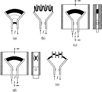
FIGURE 14.1
Methods to influence the arc on current interruption: (a) elongation on V-shaped runners; (b) meander-shaped insulating barriers; (c) elongation and confinement between insulating walls; (d) arc chute with gassing wall material; (e) partition between splitter plates.
Compared with the other arc chute principles, the deion arc chute system is mostly superior, and therefore it predominates in contactors, circuit-breakers, and similar switching devices for higher ratings. A rather global argument is that a stack of metal plates is able to consume more energy per unit volume than insulating material parts or gaseous matter.
The effect of a current loop on the arc is shown in its simplest form, parallel current rails, in Figure 14.2. The current path generates a magnetic field B perpendicular to the drawing plane. Under the assumption that the current flows within a thin thread in the center of the rails and assuming l1 ≫ k, the flux density in the arc center between the rails becomes . Examples of magnetic fields for less simplified structures are given in [6]. Together with the arc current a Lorentz force F is generated, which is directed to the right and tends to enlarge the area of the loop, thus making the arc move.
Figure 14.3 shows the effect of ferromagnetic materials like deion plates on the arc, which is a current-carrying conductor. For a conductor at distance a in front of a semi-infinite space with μr > 1 (Figure 14.3a) the ferromagnetic distortion of the self-field of the arc generates a blast field.
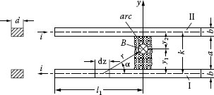
FIGURE 14.2
Generation of magnetic blast field by parallel rails.
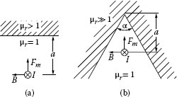
FIGURE 14.3
Principle of arc attraction by ferromagnetic plates: (a) straight front side; (b) V-shaped front side.
(14.1) |
in its axis, which attracts the arc toward the ferromagnetic space. For a V-shaped ferromagnetic material with (Figure 14.3b) it is increased by a factor of (n – 1), where .
For this reason, the sides of deion plates facing the undivided arc are often V-shaped or serrated to facilitate the arc splitting. Some examples are given in Sections 14.3 and 14.4. These measures enhance the attractive magnetic field, at least locally, and by squeezing portions of the arc they additionally increase the local arc voltage drop adjacent to the metal plates. It is necessary to increase the voltage of the yet undivided arc above the minimum arcing voltage, before the formation of new anode and cathode spots splits it up.
Apart from deion plates, the ferromagnetic attraction of the arc or of parts of it is used in various forms, for example, as a ferromagnetic layer on arc electrodes to move the arc in the direction of the ferromagnetic material. A different application of ferromagnetic material is to concentrate the self-field of current-carrying conductors on certain areas, such as the space between the contacts. Detailed descriptions of such designs would require much more space. A very general qualitative formulation to assess the direction of forces by ferromagnetic parts is that the field lines tend to flow through the areas of lowest magnetic resistance. Of course, the magnetic fields and forces of rather complicated structures, including the effect of eddy currents, are nowadays accessible to numerical computation [7]. Typical values of the self-field in the arc axis lie in the order of several tens of mT per kA arc current [8,9].
14.1.3 Arc Dwell Time on the Contacts
When an arc is established at contact opening, it does not move immediately under the influence of the magnetic blow-out field [8,10,11]. Its roots first dwell at the location of arc establishment, while parts of the plasma are already deflected in the Lorentz force direction in the form of plasma jets. Only after a certain time—or when a certain minimum contact separation is reached—does the arc move off the contacts onto the arc horns. This process is accompanied by a steep voltage rise as the arc is lengthened. Figure 14.4 shows a typical current and voltage oscillogram of such a process. Dwell times typically lie between a fraction of a millisecond (Figure 14.32) and several milliseconds. A more detailed consideration can further distinguish between different phases of dwelling [11], but for practical application, the time when the arc leaves the contacts is essential. The reason for dwelling is that the conditions for charge carrier production at first only exist at the original arc spots. For the arc to move, the preconditions for new arc spots must be created in the forward direction. This happens by magnetically deflected plasma jets that emanate from the old spots and that heat the electrodes to form new spots. For sufficient deflection of the plasma, a certain contact distance is necessary. Strongly vaporizing contact material produces rather stiff jets that are more difficult to deflect [12]. Therefore, the dwell time and minimum contact separation, respectively, depend on the material, current, opening speed, and magnetic blast field. A comparison of dwell times under conditions of miniature circuit-breakers is given in Figure 14.32, Section 14.4.6.
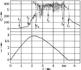
FIGURE 14.4
Oscillogram of an arc moving off the contacts into an arc chute under magnetic field influence (current-limiting miniature circuit-breaker), t1, the contacts part and the arc forms; t2, arc moves off contacts; t2 – t1, is the dwell time; t3, the arc is elongated and splits up within arc chute; t4, t5, t6, are examples of arc back-commutation; t7, the current is zero and the arc extinguishes.
The start of arc motion as well as the subsequent motion is often not a continuous process but rather a sequence of forward-commutations [13]. Jumping across a gap in the course of arc motion, for example, from the moving contact part to the fixed arc runner in Figure 14.22b, is a similar process and can also slow down the arc motion [14,15].
14.1.4 Sticking and Back-Commutation of the Arc
At high currents, it may become a problem that the arc fails to completely elongate along the diverging arc horns but sticks at the edge of the parallel rails or remains across the whole length of the horns [16,17]. This can be explained by an increasing voltage demand of the elongated arc versus the well-conducting short old channel. The current limit where this may occur depends among other things upon the width of the arc chute and the angle of the horns. Figures 14.5 [17] and 10.22 give examples of such limits. Rather similar processes are back-commutations after the arc has already reached the chute and has split up into series arcs. Such a behavior, which is associated with voltage breakdown, can be seen in Figure 14.4. The arc voltage, which sharply rises as the arc elongates and splits, acts as a source for reheating and reignition of the still hot region between the arc horns or contacts that has been left behind by the arc [18]. These undesirable processes can be shifted toward higher currents by appropriate design, for example, vents in the walls, and magnetic fields.
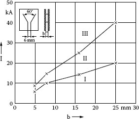
FIGURE 14.5
Current limits of unhindered arc elongation: I, arc moves to tips of arc runners; II, intermediate region; III, arc lasts as a broad band between arc runners.
14.2 Contacts for Switching in Air
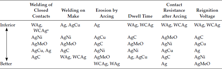
Contact materials, their shapes and manufacturing technologies are treated in Chapters 16 and 17. Details about contact performance and testing are treated in Chapter 18. The contact parts in devices for medium- and high-current switching have to withstand a variety of different stresses [2,6,19], which are summarized, together with the requirements for contact materials, in Table 14.1. As several of these requirements are contradictory to each other, no contact material can fulfill all of them equally well. The development and selection of materials for certain applications is therefore always a compromise. Table 14.2 (according to [6,19]) is a summary of the sequence of different contact materials with respect to different stresses. It is of course only very crude, as the behavior depends on many design and circuit parameters, and the contact manufacturing details are important as well.
Table 14.3 finally is a summary of the application of contact materials in different low-voltage switching devices working in air [19,20]. The general trend is to use either pure silver or silver alloys for low duty, while for higher currents special erosion- and weld-resistant compound materials prevail. Some of those materials usually have some other drawbacks that must be overcome by the device design, like higher contact resistance, longer arc dwell time, or lower reignition voltage. As can be seen, the use of asymmetrical contact pairs, that is, different contact materials on both contacts, is widespread. Especially with AgC against either pure copper, AgNi, or materials from the WAg–WCAg group, the advantages of both partners are combined in circuit-breakers. At arcing the graphite content prevents the formation of tarnish films (contact resistance rise), and it reduces the weld tendency. On the other hand, the drawbacks of AgC—high erosion and long dwell time—are diminished by combination with materials like AgNi or Cu.
TABLE 14.1
Stresses and Requirements for Contact Materials
Operation |
Strain/Problem |
Requirement |
Making |
Contact bouncing, welding by bounce arcs |
Little weld tendency Low weld forces |
Erosion by bounce arcs |
Low and uniform make erosion |
|
Mechanical wear |
Low wear |
|
Closed contacts |
Heating under operational conditions |
Low contact resistance |
Heating and welding on short-circuit |
Low contact resistance |
|
Dynamic lift-off and welding on short-circuit |
Little weld tendency, low weld forces |
|
Breaking |
Erosion by breaking arcs |
Low break erosion |
Immobility of arc roots |
Short immobility time |
|
Arc extinction |
Fast recovery |
|
Reaction with surrounding medium on arcing, contact resistance increase |
Constant low contact resistance |
|
Reduction of insulating level by metal deposition |
Nonconducting deposits |
|
Open contacts |
Electric stress |
Sufficient insulation |
Tarnish formation, contact resistance increase |
No formation of detrimental films |
TABLE 14.2
Sequence of Silver-Containing Contact Materials with Respect to Different Stresses
a Early welding, but weld forces only weak.
AgMeO, silver-metal oxide (AgCdO, AgSnO2).
The principal function and mechanical design aspects are treated first. The relevant physical mechanism of arc quenching leads to different typical arc chute designs, depending on the ratings of the contactor. The choice of contact materials is governed by the requirements for safe operation and long service life. While in most IEC contactors for low-current ratings AgNi contacts are predominant, silver–metal oxide compound materials prevail for larger sizes. For many years, intensive work has been undertaken to replace AgCdO by materials with less toxic metal oxides, especially AgSnO2. Characteristic differences in their behavior and the present knowledge about the reasons are summarized. Finally, new trends in contactor development are mentioned.
TABLE 11.7
Application of Contact Materials in Different Low-Voltage Switching Devices
Application |
Continuous Current Rating |
Interrupting Capacity |
Contact Material |
|
Relays and auxiliary contacts |
≤10 A |
≤100 A |
Ag, AgCu (3–10% Cu) AgCdO (10–15% CdO) AgNi (10–20% Ni) |
|
Contactors |
≤10 A |
≤150 A |
AgNi (10–20% Ni) AgCdO (10–15% CdO) AgSnO2 (8–12% SnO2) |
|
>10 A |
>150 A–10 kA |
AgCdO (10–15% CdO) AgSnO2 (10–12% AgSn02) |
||
Residential circuit-breakers, US type |
≤125 A |
≥10 kA |
MoAg (25–50% Ag) |
WAg (50% Ag) |
Switching duty residential breakers |
≤30 A |
≤10 kA |
WAg (25–50% Ag) MoAg (Ag-enriched surface) AgCdO (10–15% CdO) AgZnO (8–10% ZnO) AgSnO2 (8–10% SnO2) |
|
Residential circuit-breakers, European type |
≤63 A |
≤10 kA |
AgCdO (10–15% CdO) AgSnO2 (10–12% SnO2) AgC (3–5% C) + Cua |
|
>10 kA |
AgC (3–5% C) + AgNi (40–50% Ni)a AgZnO (8% ZnO) MoAg (25–50% Ag), WAg |
|||
Industrial type circuit-breakers without extra arcing contacts |
≤400 A |
≤25 kA |
AgC (3–5% C) + AgNi (40–50% Ni)a AgC (3–5% C) + WAg (25–50% Ag)a |
|
≤800 A |
≤100 kA |
WAg (25–50% Ag) WCAg (35–50% Ag) MoAg (30–50% Ag) |
||
Circuit-breakers with main and arcing contacts |
>400 A |
<150 kA |
Main contacts: AgNi (20–40% Ni) AgCdO (10–15% CdO) MoAg (50% Ag), AgW (25–50% W) WCAg (35–50% Ag) Arcing contacts: WAg (20–35% Ag) WCu (30–50% Cu) WCAg (30–40% Ag) |
a Asymmetrical contact pair.
Contactors are remote control switches actuated electromagnetically or pneumatically. Pneumatic contactors are disregarded here as they play only a minor role. Most contactors are self-resetting, that is, they move into one position (in main circuits generally the ON-position) when their magnetic actuator is energized and they return to the original state when its excitation is switched off. They are used in a wide field of applications, such as switching small currents in auxiliary circuits, ohmic loads in heaters, capacitive currents for power factor compensation, or motor loads up to many hundred kilowatts or even megawatts. Standards distinguish between contactors in auxiliary circuits and in main circuits of electrical power engineering. I will mainly concentrate on motor switching, so-called motor starters, as this is one of the most common duties of contactors. There are other switching devices for motor load switching, for example, hand-operated motor starters. Apart from the actuator mechanism, their main parts like contacts and arc chutes are very similar to those of contactors.
Contactors provide a high operational life, for example, 10 million mechanical operations for smaller contactors and between tens of thousands and over a million switching operations under electric load, depending on the load conditions. A considerable amount of all the contact material produced worldwide goes into contactors, and many papers on the contact performance refer to contactors [21,22,23,24,25,26].
Mainly low-voltage (≤1000 V) air-break contactors are treated here. Vacuum contactors that also play a role, especially in the region of higher current and voltage ratings, are treated in Section 14.6.
As for other technical products, the duties of contactors, as well as other switching devices like circuit breakers are fixed in “Standards”. Worldwide two main regions have influenced the technology and standardization: North America and Europe. The first is represented through NEMA, UL, and CSA and their standards [27,28,29,30], the second through IEC and VDE, today harmonized in the European Community as EN/IEC standards [31,32,33]. They represent two different philosophies in standardization as well as different habits in the selection and application of contactors. NEMA defines several sizes of contactors and prescribes ratings for different duties, depending on the size. IEC differentiates primarily between various utilization categories, representing the typical loads. As a very rough generalization, the NEMA standard requires a larger device for a certain switching purpose, while the IEC standard needs a more detailed consideration of the circumstances of application [34]. Successive harmonization between IEC and UL standards has been started, however, and will take place in the future.
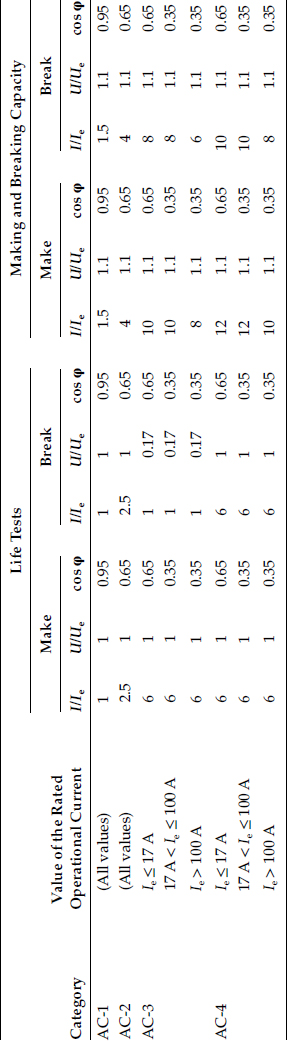
Table 14.4 summarizes the major utilization categories and test duties of contactors for ac switching according to IEC [31]. The most frequently discussed categories are AC-3 and AC-4. AC-3 requires making currents of 6Ie and breaking currents 1Ie (Ie = rated operational current), representing starting of squirrel-cage motors and switching them off during running. AC-4 defines 6Ie on make and break. These conditions exist when the high motor inrush currents are switched off again before a drive has really started to move, or when inching, plugging or reversing is employed. Additionally, the required make and break capacities for occasional operations lie even higher.
Figure 14.6 shows several principal arrangements of the magnetic actuator in relation to the contact system [35,36]. In all cases, the three or more current paths are arranged one behind the other in the viewing direction and actuated by the same magnet. Figure 14.6a represents the old system of clapper contactor, still in use for some special high-capacity contactors and in medium voltage vacuum contactors. The moving parts of the magnet and of the contact system are fixed on a rotating bar. By appropriate design of the lever arms of the magnet and the contacts, the available magnet force can be adjusted to the contact force characteristics. This type usually uses single break contacts. The space requirement of clapper contactors is relatively high. Figure 14.6b shows a variant of this principle with an additional toggle lever. By its means the closing speed can be diminished to reduce bouncing, and the contact force is increased. On the other hand, this measure also reduces the opening speed. The principle is mechanically complicated and therefore seldom used in contactors. In contrast to these two schemes, the two following ones, using magnets with linear motion, are more frequently found in modern contactors. Figure 14.6c is based on a rotating lever, coupling the magnet and the contact system. This implies an additional degree of freedom by choosing the gear ratio between the magnet and the contacts, and has some advantages with respect to the accessibility of both the contact system and the actuator magnet. As the magnet is arranged side-by-side with the contact system, and the lever is an additional part, the space requirement is somewhat higher than for the following arrangement. Finally, Figure 14.6d represents the mostly used principle, where the actuator and the contact system are arranged within one block one on top of the other and coupled directly. The lacking possibility of mechanically fitting the magnet characteristics to the contact system can be overcome by appropriate electrical design of the magnet and its coil. This system enables compact and cost-effective devices.
TABLE 14.4
Conditions for Life Test and Make-and-Break Test of Contactors According to IEC 60947-4-1 (Simplified)
While Figure 14.6a is a single break, Figure 14.6b through d show double-break arrangements as used in most contactors. The consequences for the electrical behavior are discussed later. For the actuator, a double-break means roughly that it has to provide double the contact force.
Figure 14.7 is a schematic view of the mostly used contactor type with direct actuation, including the contact and opening springs [37]. The contacts are kept in the open position by the opening springs 5. When the coil is energized, the contacts are driven down together with the moving actuator element 8, until the contacts make, and the force of the contact spring suddenly becomes effective between the fixed and moving contacts. When the excitation ceases, the loaded spring 5 accelerates the moving parts toward the open position, at first supported additionally by the contact springs. The static force requirement for the actuator is schematized in Figure 14.8. It must be more than compensated, at least dynamically, by the magnetic force (dashed line).
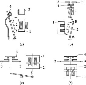
FIGURE 14.6
Arrangement of magnetic actuator in contactors: (a) clapper contactor; (b) clapper arrangement with toggle lever; (c) actuator with lever coupling; (d) direct actuator. 1, fixed magnet part; 2, moving magnet part; 3, fixed contact part; 4, moving contact part.
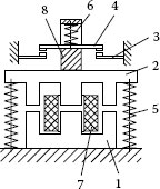
FIGURE 14.7
Arrangement of actuator, contact system, and springs: 1, fixed magnet part; 2, moving magnet part; 3, fixed contact part; 4, moving contact bridge; 5, opening springs; 6, contact spring; 7, magnet coil; 8, actuator element.
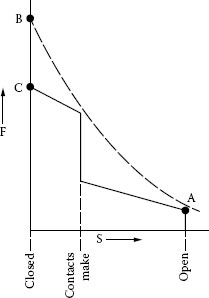
FIGURE 14.8
Scheme of static forces for a contactor magnet.
Though it would require an extra monograph to cover the essentials of magnetic actuators, some main features shall be mentioned here. Figure 14.9 summarizes different typical shapes of magnets [35,37]. In addition to the shape, the main differentiation lies between ac and dc magnets. Many manufacturers offer these systems optionally and with different voltage ratings. To avoid ac losses, the iron cores of ac magnets have to be laminated. Additionally, they need shading coils, that is, shorted one-turn windings that surround partial areas of the magnetic poles (see Figure 14.9g). Their effect is to generate a partial flux phase-shifted against the remaining flux. The superposition of both fluxes prevents the force from becoming temporarily zero, and thus reduces noise and mechanical wear [35,37,38]. dc magnets have no problems with such force fluctuations of double line frequency.
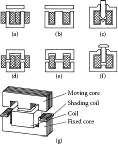
FIGURE 14.9
Typical shapes of magnets.
All magnets must exceed the force of point A in Figure 14.8 when starting to close. The dependence of the force on the magnetic air gap leads to an excess of the available (B) over the necessary force (C) in the closed position, which might cause an unnecessarily high speed and kinetic energy at closure. Stronger contact bouncing and mechanical wear are the consequences. DC magnets can be better designed to feature lower excess forces and softer closing. For all magnets the necessary hold current in the closed state is only a small fraction of the pull-in current at point A. As their inductance is much smaller in the open than in the attracted state, ac magnets automatically meet both requirements, without the necessity to change the excitation by switching. In conventional dc-driven contactors, either the number of coil windings is switched or the hold current is reduced by inserting an additional resistor, both by means of auxiliary contacts. The latter method is associated with additional ohmic losses. New electronic solutions are increasingly gaining interest here (see Section 14.3.5). Depending on the contactor size, the contact stroke lies between a few millimeters and 1 cm per break. The average contact opening and closing speeds lie typically between 0.3 and 1.0 ms−1.
14.3.3 Quenching Principle and Contact and Arc Chute Design
Contactors are generally devices quenching at current zero. In ohmic-inductive circuits, after the current has reached zero, the line voltage reappears across the switching gap in the form of the transient recovery voltage (TRV). Its frequency depends on the load and lies between several kilohertz and well above 200 kHz [31]. The arc that has been initiated by contact separation several milliseconds earlier must withstand this TRV within a microsecond frame. In the majority of contactors, the physical principle of immediate recovery is effective [3,39,40] (Section 9.7.1). Even without any additional arc chute, an ac arc between two electrodes is able to withstand a certain voltage immediately after current zero without restrike. Only when this voltage is exceeded does reignition and subsequent current flow occur (Section 9.7.1). This voltage is referred to as the instantaneous recovery voltage.
Besides the recovery of the cathodic space charge sheath, cooling of the arc column, especially when gases from decomposing insulating walls are involved, may additionally support arc extinction [41,42], but wall erosion also limits the operational life.
Figure 14.10 is a plot of measured instantaneous recovery voltage (average) for different contact materials at different currents. It clearly depends on the thermal and electrical properties of the electrode material, as well as the thermal arc stress on the contacts. The general tendency is a decrease with increasing arc current (see Figure 9.55), but contact materials with components of low boiling or sublimation temperatures, such as AgCdO, stay remarkably constant up to high currents [8,40]. Additives or impurities may also exert a strong influence [43]. While in small installation switches up to 20 A and 230 V one contact gap is sufficient to withstand the maximum TRV, higher currents and r.m.s. voltages of 400 or 690 V in three-phase systems already reach the limit of self-extinction. By connecting two gaps in series the breakdown voltage is nearly doubled, and thus, this principle extended to higher ratings. Figure 14.11 demonstrates this for several contact materials [44]. Most contactor relays for auxiliary circuits and small motor contactors up to Ie = 20 A use such double-break contacts without an additional system to influence the arc.
Another advantage of the usual double-break contact systems with two fixed contacts and one moving bridge (Figure 14.6b through d, Figure 14.12a through d) is that no flexible connections between the moving contacts and their terminals are needed. They might constitute a serious mechanical problem to contactors with their high number of operations. In contrast to circuit-breakers, the currents in contactors are not extremely high, so the drawbacks of the double-break, namely higher contact resistance and higher total contact force, are acceptable.
There have been contactor designs in the market that even connected two double-breaks in series to form a fourfold break [6]. However, this arrangement is costly, and there are four sources of heating. When the plain double-break system is not sufficient any longer—typically at rated currents beyond 20 A—the next step is to move the arc on each side off the contacts by magnetic forces and to split it up into two arcs by means of an additional isolated metal electrode—often as a U-shaped iron sheet lining the arc chamber similar to that shown in Figure 14.12b. This results in a total of four immediately recovering gaps.
At ratings above Ie = 50 A, most contactor designs split up the arcs in even more partial arcs by means of iron splitter plates (“deion arc chute”). Figure 14.12c,d shows examples for such arrangements in contactors.
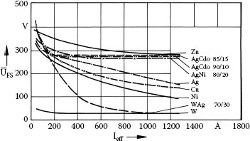
FIGURE 14.10
Instantaneous recovery voltage (average) for different contact materials vs. r.m.s. current.
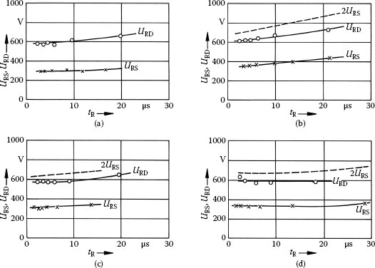
FIGURE 14.11
Reignition voltage vs. time after current zero for different contact materials on single and double break contacts: (a) Ag; (b) AgNi 90/10; (c) AgCdO 90/10; (d) AgSnO2 88/12. U = 750V, I = 103 A, fTRV = 10 kHz, URD, double break, URS, single break.
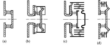
FIGURE 14.12
Typical contact and arc chute arrangements of contactors: (a) without additional quench system; (b) insulated steel lining; (c) plates parallel to arc axis, U-shaped fixed contact parts; (d) plates perpendicular to arc axis, straight fixed contact parts.
Figure 14.13 shows reignition voltages versus the actual number of partial arcs in series between iron plates [2,8]. The current range concerns big contactors and smaller circuit-breakers, respectively. Owing to uneven voltage distribution, the reignition voltage grows less than proportionally with the number of arcs. It can be seen that gas-evolving polymer wall material helps to cool the system and increase the reignition voltage.
In any case, the arcs established on contact separation (dashed in Figure 14.12) must be moved to the deion system along arc runners or arcing horns and must create new anode and cathode spots at the steel plates. This is facilitated by U-shaped current paths of the fixed contacts (Figure 14.12b,c) that form a loop together with the current path in the bridge, thus generating a magnetic blowout field. This current path is drawn separately in Figure 14.14. As a drawback, the loop increases the magnetic blow-off forces that tend to open the contacts when high inrush currents are switched in. Furthermore, it is space-consuming. Some designs do not use U-loops but iron parts along the arcing horns to concentrate the magnetic self-field onto the arc area; others use both features. There is a wide variety of details with regard to the arrangement of arc runners, splitter plates, and additional iron parts to direct magnetic fields [2,6,45,46]. As an example, Figure 14.15 shows a complete cross-section of a larger contactor [45].
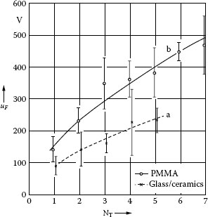
FIGURE 14.13
Reignition voltage (mean and standard deviation) vs. number of partial arcs in series: (a) nongassing wall material; (b) gassing wall material. I = 5000 A, U = 500 V, fTRV = 600 kHz, steel splitter plates.
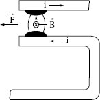
FIGURE 14.14
Typical current path arrangement for self blast field in contractors.
Figure 14.16 gives a summary of different shapes of deion splitter plates of larger contactors [6]. Their sides facing the undivided arc are often V-shaped or serrated to facilitate the arc splitting. They increase the attractive magnetic field, at least locally (compare Figure 14.3b), and by squeezing portions of the arc they increase the local voltage drop. It is necessary to increase the voltage of the yet undivided arc above the minimum arcing voltage before splitting occurs. Figure 14.12c,d also show that different orientations of the plates relative to the arc axis are usual. Figure 14.12c additionally is an example of how the moving bridge can be relieved from the arc stress by commutating the arc roots onto a fixed conductor connecting both arc chutes.
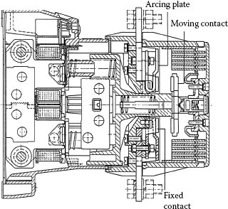
FIGURE 14.15
Cross-section of an ac contactor with 400 A rated operational current.
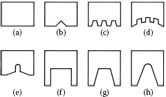
FIGURE 14.16
Shapes of deion splitter plates in contactors.
When looking at the contact materials used in European contactors, two main groups can be distinguished:
Contactor relays and small contactors with operational currents of a few tens of amperes (switching currents to 200 A) use pure silver, hard silver with small alloying additions to increase the mechanical and thermal strength of silver (e.g., Ag with 3% Cu), or in most cases silver-nickel. Silver-nickel is a compound material produced by sintering processes from the metal powders. Usual compositions for contactors lie between 90/10 and 80/20 per cent by weight.
For contactors with higher ratings, silver-metal oxide (AgMeO) compound materials have been the standard worldwide for several decades, and they are still the first choice. Detailed summaries of their properties and their development are published in [23,24], see also Chapter 16. They are either manufactured by sintering processes or by internal oxidation of silver-metal alloys. It is a well-known fact that the characteristics of these contact materials may widely differ, depending on the composition, the additives and impurities, and the manufacturing process and its parameters. Usual compositions are Ag with 8–15 wt% of oxide. AgCdO materials used to be the optimal choice for a long time, but other oxides like CuO, ZnO, or SnO2 have also been under consideration. Starting in the 1970s, the development work was intensified to replace the toxic CdO by less harmful components. The proceedings of all contact conferences since then reflects this development. AgSnO2 was found to show remarkably low erosion at high loads in comparison with AgCdO, as well as high resistivity against welding. It was soon found, however, that AgSnO2 led to higher contact resistances which, in turn, led to higher heating, as a result of its more stable oxide. After intensive research work in many places with additional small amounts of further components, this behavior could be considerably improved [22]. As far as it is understood now, such additives—for example, oxides of refractory metals [47,48]—modify the morphology of the melt at the contact surface.
AgSnO2 materials have already replaced AgCdO in many new contactor designs. Especially in conjunction with the introduction of AgSnO2 (10–12% SnO2 by weight) it is a widely accepted truth that it is not optimal to just replace an existing contact material by a new one, but to optimize the switching device together with a contact material. While at first the longer service life of big contactors with these AgSnO2 materials under AC-4 conditions (high make and break currents, Figure 14.17a [49]) was the outstanding feature, it was soon found that under AC-3 load AgSnO2 may lead to a distinctively higher wear than AgCdO [49,50,51]. There are also strong dependences of the ranking on the design and size of the contactor, as can be seen from a comparison between Figure 14.17b and Figure 14.17c [49]. Measurements under make-only and break-only conditions show that the make erosion of AgSnO2 may be two-to-three times higher than that of AgCdO, whereas the break erosion is smaller [46]. Owing to the much higher make current, the make erosion dominates on AC-3. Present interpretations suppose that the differences also lie in the properties of the contact material melt, and in the behavior under the impact when the contacts close (bouncing) [25,26,50]. Work is going on to improve this behavior by minor additives of third of fourth components.
It is often observed that especially the make erosion may widely differ between different designs, between different specimens of the same design, and between the three phases of one specimen. The latter is easily explained by a synchronizing effect of ac-fed actuator coils. Investigations where the actual bounce arc pattern and the arc energy on make have been evaluated [52] show that this energy strongly varies. In a three-phase circuit with floating star point a mechanical contact lift-off does not necessarily mean an arc. Depending on the mechanical properties of the design and of the individual specimen as well, the bounce pattern varies and consequently the time and current magnitude of the bounce arcs that are actually formed are subject to strong differences. Figure 14.18 gives an example of the measured lowest (1) and highest life (2) of a contactor type, as well as estimations (3) derived from the bounce patterns [52]. Variations of 3:1 or even 4:1 may occur.
Besides the general trend to develop better, even more reliable, and more compact contactors, and to further improve their handling and mounting, some specific trends should be mentioned briefly, as far as contactors in main circuits are concerned.
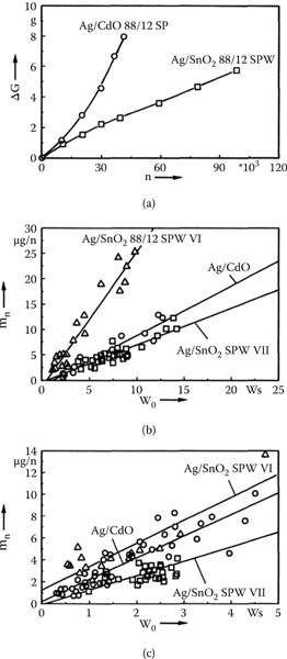
FIGURE 14.17
Erosion of AgCdO and of different variants of AgSnO2: (a) AC-4, phase with strongest erosion, erosion vs. no. of operation; (b) AC-3, contactor type A, average erosion vs. arc energy; (c) AC-3, contactor type B, average erosion vs. arc energy.
14.3.5.1 Contactors versus Electronics
It is often discussed whether electromechanical devices like contactors will have chances in the future in comparison with fully electronic solutions [53,54]. The answer should be differentiated between main circuits and auxiliary circuits. Unless completely new electronic elements are discovered, the contactor will essentially keep its position as a switch for main circuits because of its advantages in view of much smaller losses, much smaller volume, smaller costs, and its isolating properties. Control circuits with contactors are being increasingly replaced by programmable controllers. But on the other hand, the number of contactor relays used as output interfaces between electronic controllers and actuators is rising, and the manufacturers still register constant or slightly growing numbers.
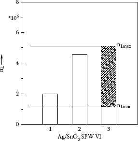
FIGURE 14.18
Measured and expected AC-3 life for AgSnO2 88/12 SPW VI in a contactor. 1, lowest; 2, highest measured life; 3, estimated spread of life (shaded).
The low-voltage vacuum contactor (see Section 14.6) has already gained some importance, especially at higher current ratings (150 A–1000 A) and for special applications like mining. Its advantages are the completely sealed contact system (no contact resistance problems, no environmental problems), the high switching capacity, and a long operational life. It seems to be mainly a question of manufacturing costs whether the vacuum principle will be able to penetrate more into the lower-current regions.
Hybrid contactors are a combination of metallic contacts to carry the current with power electronics elements for the switching operation [50]. This reduces contact erosion and increases contact life considerably. Though technically excellent, this principle is costly for switching alone, and it is still limited to special cases.
14.3.5.4 Integration with Electronic Systems
There will be an increasing integration of electromechanical components into the systems of automation technology, and vice versa. Though solid state devices will partly replace traditional mechanical switching in various applications, the overall use of electromechanical contacts will remain and even be extended [55,56].
• Motor Control. Instead of switching motors just on and off at full load, more intelligence is used to reduce the electrical and mechanical stresses on closing and opening, or to save energy during operation. Adjustable Frequency Drive Control is fully based on solid state technology. Soft Starters [57] also use solid state control at switching on and off or reversing. Additional contacts switched parallel to reduce the losses form a hybrid arrangement [58].
• Integration of contactors into bus systems [59]. It is a tendency to integrate more and more intelligence into contactors and the surrounding system, from the simple monitoring of the switch position—in conventional contactors achieved by auxiliary contacts—to the diagnosis of the remaining life expectancy of the contactor. This can be achieved by counting the number of switching operations or better by additionally measuring their severity, and even stop the operation when a predefined contact wear is reached. In a similar way, it is possible to monitor the aging of other devices in the circuit, for example, of motors [60].
• Electronic control of magnet coils [33,61,62]. By appropriate electronic control of the coil voltage and current, respectively, the mechanical pull-in characteristics can be influenced much better than by the conventional technique. It is possible to minimize bouncing at contact closure, an appropriate measure to improve the performance of AgSnO2 under AC-3 conditions [63]. Other features are that the operating voltage range can be increased and that the number of coil variants for different frequency and voltage ratings can be drastically reduced. Also the size of the magnet and coil can be minimized, especially with dc actuators.
14.4 Low-Voltage Circuit-Breakers and Miniature Circuit-Breakers
Significant differences for example, between circuit breakers per IEC and UL/CSA are larger clearance and creepage distances and higher requirement of individual pole short-circuit breaking capacity with UL/CSA. Besides normal operational currents and overload currents, circuit-breakers must be able to switch over-load currents and short-circuit currents on and off. The IEC standards [64] differentiate between two utilization categories: Category A comprises circuit-breakers that are not specially designed for selectivity, and category B circuit-breakers that are designed for selectivity under short-circuit conditions. Selectivity of two circuit-breakers in series means that only the circuit-breaker on the load side interrupts, while the one on the feeder side remains inactive. This is usually achieved by short-time delay short-circuit release. The circuit-breaker must then be able to withstand the stress during the delay time. Some standardized data concerning the making and breaking capacities of circuit-breakers are summarized in Table 14.5 [64]. While the breaking capacity is defined as r.m.s. value, the making capacity is defined as the maximum peak value of the prospective short-circuit current. The required short-circuit switching operations are shown in Table 14.6. In any case, the circuit-breaker has to make and break its full rated short-circuit current only a few times. Depending on the rated current, the required number of switching cycles without current (mechanical) lies around several thousand, the number of closing-opening operations under normal load between 500 and 1500 [64].
TABLE 14.5
Standard Relationship Between Short-Circuit Making and Breaking Capacities, and Related Power Factor, for AC Circuit-Breakers (IEC 60947-2)
Short-Circuit Making Capacity (kA r.m.s) |
Power Factor |
|
4.5 < I < 6 |
0.7 |
1.5 |
6 < I < 10 |
0.5 |
1.7 |
10 < I < 20 |
0.3 |
2.0 |
20 < I < 50 |
0.25 |
2.1 |
50 < I |
0.2 |
2.2 |
TABLE 14.6
Short-Circuit Test Sequences for Circuit-Breakers (IEC 60947-2)
Denomination |
Test Sequence |
Tests to Pass after Short-Circuit Sequence |
Test sequence II: Rated service short-circuit breaking capacity |
O – t – CO – t – COa |
Insulation voltage Heating under load Overload tripping |
Test sequence III: Rated ultimate short-circuit breaking capacity |
O – t – COa |
Insulation voltage Overload tripping |
a O opening operation (by release) C closing operation.
CO closing-opening operation t pause (3 min).
There are separate standards on miniature circuit-breakers for residential and industrial installations, for example, [65,66], but there are no basic differences to other circuit-breakers in function and general design of the contact and arcing systems.
Low-voltage circuit-breakers are operated by latched springs which are charged either manually or by electric motors. As far as their operational principle is concerned, two variants can be differentiated:
• Circuit-breakers with high current-carrying capability, able to withstand the short-circuit current for some time, for example, several cycles to one second (“dynamically and thermally rigid” breakers). They are suitable for time-delay tripping (utilization category B), that is, the contacts must stay latched until the breaker is being tripped. They usually have higher rated continuous currents (630–4000 A) and are often built as open devices where the actuator mechanism, the trip system, the contacts, and the arc chutes are mounted together on a steel frame (example in Figure 14.19 [2]). Other designs of this type are built as molded-case circuit-breakers (MCCB). This type is more used in the upper hierarchy of low-voltage power distribution, for example, as feeder circuit-breakers for busbars. Owing to the time delay they do not limit the short-circuit current, and it makes no sense to construct their contact systems and arc chutes specially for current limitation. Nevertheless, the impedance of the tripping device and the arc voltage often cause a certain current reduction against the prospective current.
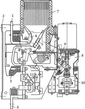
FIGURE 14.19
Non-current-limiting 1250 A circuit-breaker in open construction: 1, upper terminal; 2, steel frame; 3, insulating plate; 4, fixed contact piece; 5, moving contact piece; 6, lower terminal; 7, arc chute; 8, motor drive; 9, cam disk; 10, centrifugal weight; 11, overcurrent trip unit.
• Circuit-breakers provided with fast-acting trip- and contact-opening mechanisms, where the arc voltage is rapidly increased on short-circuit to limit the actual current to values well below the prospective currents. These breakers with rated continuous currents between 16 A and several 100 A are generally built as molded-case circuit-breakers [5,29]. The molded case, typically of reinforced polymer, provides both the insulation and the mechanical support structure for mounting all other components. Figure 14.20 [2] is an example of a current-limiting MCCB. Their main application lies more downstream in the power distribution system.
Combined principles are also realized, such as breakers behaving dynamically rigid up to a certain current and current-limiting beyond.
14.4.3 Quenching Principle and Design of Arc Chute and Contact System
Circuit-breakers may use two different physical principles of arc interruption. The first is ac interruption at current zero, where the arc has to lose its conductance quickly when the ac current passes through zero. It has already been treated in Section 9.7.1. These breakers are not current-limiting. The second principle is the principle of dc interruption as treated in Section 9.7.2, where the arc voltage must be increased above the system voltage. It is utilized for switching in dc circuits, which is presently still relatively rare, but becoming more important, and far more for current-limiting switching in ac circuits (see also Section 9.7.4). Figure 14.21 shows the principal current and voltage evolutions on current-limiting switching. For an effective limitation, the arc voltage must be raised above the momentary system voltage well before the prospective short-circuit current has reached its first peak, that is, within a few milliseconds. By this the dynamic stress, which is proportional to the square of the peak let-through current , as well as the thermal stress, which grows with of the system under protection, are reduced considerably. The current limitation works only under short-circuit conditions where the trip time is short enough. Under nominal load current or over-load current there is no limitation.
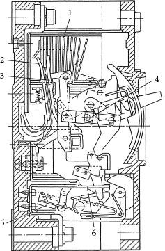
FIGURE 14.20
Current-limiting molded-case circuit-breaker (MCCB) for 225 A rated continuous current: 1, arc chute; 2, fixed contact piece; 3, moving contact piece; 4, operating mechanism; 5, undelayed trip device; 6, overload trip device.
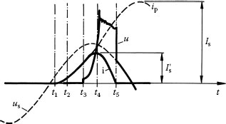
FIGURE 14.21
Principle of current limitation in ac circuits: u, arc voltage; uS, system voltage; i, current; ip, prospective current; Is, prospective peak current; , let-through current; t1, beginning of short-circuit; t2, tripping; t3, contact opening; t4, arc voltage reaches system voltage, current is limited; t5, current interruption.
Nearly all low-voltage air circuit-breakers, if they are current-limiting or not, use arc chambers with steel splitter plates for quenching. Though, as explained in Section 14.1.1, the physical principles are quite different between current-limiting breakers and breakers using current zero interruption, the shape and number of deion plates may not differ substantially between them. The reason is that the current-zero reignition voltage of arcs between steel electrodes continuously decreases with current and finally approaches the arc voltage of a few tens of volts after arcing at high currents of tens of kiloamperes. The necessary number of partial gaps in series, either for the arc voltage to exceed the system voltage for current limitation, or for the reignition voltage after current zero to exceed the TRV, lies therefore in the same order.
14.4.3.2 Arc Chute and Contact Arrangement
Contrary to contactors the majority of low-voltage circuit-breakers use one break per phase, which necessitates a movable connection between the moving contact piece and its terminal. Two breaks need a higher total force and a more complicated construction of the operating mechanism. Also the heating power generated during continuous current load is double. Figure 14.22 shows two typical examples of contact and arc chute arrangements; there are many additional variants. Some characteristic arc positions are also drawn. The deion plates are only schematic, their number is usually higher (compare Figures 14.19 and 14.20).
In Figure 14.22a the arc after elongation has to stay at the tip of the moving arc horn on which the moving contact is fixed. The deion plates are arranged fan-like and surround the contacts and arc horn to increase the magnetic blow force. The steel plates are extended by insulating plates in this example. This provision which can be often found in open circuit-breakers for high currents (Figure 14.20) prevents the arc from being shorted behind the plates.
Figure 14.22b represents a system where the arc has to commutate from the moving contact onto a separate fixed arc runner that is connected to it by a flexible conductor. The moving contact piece is thus relieved from the arc stress, and the arc runners can be better fitted to the shape of the stack of deion plates. On the other hand the necessary commutation may constitute an additional source of delay [15]. There are also solutions where the fixed runner is not connected with the moving contact, but where this connection has to be made and maintained by an additional arc. The example of Figure 14.22b further has parallel plates, and has vents in the upper wall to relieve the pressure that builds up on arcing.
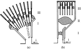
FIGURE 14.22
Schematic circuit-breaker arangements: (a) without commutation to a stationary arc runner; (b) with commutation to arc runner connected with the moving contact I, arc between contacts; II, arc in intermediate position; III, arc split up between deion plates.
Figure 14.23 [6] shows some typical shapes of circuit-breaker deion plates. They often surround the arc horns in a U- or V-shape, Figure 14.23a. This increases the magnetic attractive force. Additional slots in the center (Figure 14.23b) or staggered (Figure 14.23c) help to improve splitting at smaller currents.
The number of deion plates in circuit-breakers cannot be increased indefinitely. As explained in Section 14.1.4, sticking and back-commutations associated with voltage limitations may occur, when certain voltage and current levels are exceeded. Then it makes more sense to leave the principle of single break and to arrange two arc chutes in series, despite the other drawbacks. Some basic arrangements, which are increasingly used for quick-acting current-limiting breakers of lower continuous currents, are shown in Figure 14.24. Additionally, arrangements as in contactors (Figure 14.12) are possible.
The differences between rigid nonlimiting and current-limiting breakers lie especially in the contact and mechanical systems. Closed contacts have to withstand two different stresses when a short-circuit current flows across them (see also Sections 10.4 and 10.5):
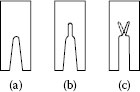
FIGURE 14.23
Deion plates for low-voltage circuit-breakers: (a) U- or V-shaped recess; (b) with central slot; (c) with staggered slots.
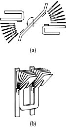
FIGURE 14.24
Arrangements of double-break systems in circuit-breakers: (a) rotating contact lever with opposite arc chutes;
• Ohmic heating of the constriction resistance with the danger of welding when the melting point is exceeded. The contact force necessary to avoid welding is
(14.2) |
where Î is the peak current and K1 is a constant that contains the electrical and thermal data and the hardness of the contact material [6,67], see also Section 10.5.1.
• Dynamic blow-off owing to the current path in the contact constriction, see Section 10.4. The contact force necessary to counteract the blow-off force is also roughly proportional to the square of the peak current,
(14.3) |
where K2 contains the geometry and also material properties.
As K1 and K2 are rather similar, it depends on the details of the design and the contact material, and one can hardly predict which of both mechanisms limits the short-circuit withstand capability of a closed circuit-breaker. In any case, the force necessary is a quadratic function of the peak current.
Rigid noncurrent-limiting breakers therefore need high contact forces. The simplest way is to use contact springs with the necessary static contact forces for the highest peak current. This requires, however, a heavy construction for the whole mechanism. Dynamic contact reinforcement, where the force is generated by the flowing short-circuit current, is a more elegant method. Figure 14.25a shows a characteristic example where the repulsion force of two anti-parallel rails is used to add to the static force via a pivot point [3]. A different way is to utilize the attractive force of two parallel current paths for dynamic inrease. Another method is to reduce the high necessary contact force by dividing the current into two or more (n) parallel contact paths. Provided the current distribution is even, Equations 14.2 and 14.3 only yield a total necessary contact force for all n paths .
The opposite has to happen with the contact system of current-limiting breakers. To limit the current effectively the contacts must be separated quickly and with little delay upon short circuit. Here, an approved method is to use the magnetic repulsion of two antiparallel and closely spaced current paths (principle in Figure 14.25b, see also Figure 14.21). This force can be considerably increased by concentrating the self-field of the current path to the moving contact arm where the force is needed. Figure 14.26 shows such a “slot motor” [5], a U-shaped laminated iron core that surrounds the anti-parallel contact arms of each phase. Another method to increase the opening speed that is often used in European current-limiting miniature circuit-breakers uses a solenoid fed by the main current (“solenoid kicker,” Figure 14.27 [5,7]). At short circuit its plunger directly acts on the moving contact part by hitting and pushing or pulling it. With such mechanisms speeds over 10 ms−1 are attainable at short circuit, while the speed at smaller currents is considerably lower, for example, 1–2 ms−1. At the same time the actuation spring is unlatched by the plunger.
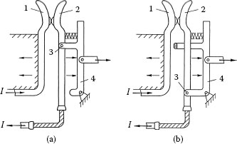
FIGURE 14.25
Dynamic intensification of (a) contact force and (b) blow-off force: 1, fixed contact piece; 2, moving contact piece; 3, pivot point of moving contact piece; 4, switching lever.
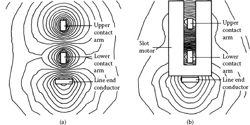
FIGURE 14.26
Function of a slot motor to increase the blow-off force: magnetic field lines (a) without and (b) with slot motor.
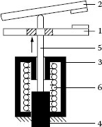
FIGURE 14.27
Principle of solenoid kicker for fast contact opening: 1, stationary contact piece; 2, moving contact piece; 3, stationary magnet yoke; 4, movable plunger; 5, nonmagnetic rod; 6, coil.
All air circuit-breakers use the magnetic self-field generated by current loops to move the arc off the contacts toward the arc chute (Figures 14.2, 14.14, 14.25). It can be increased by additional ferromagnetic flux concentrators, such as side plates isolated from the arc chamber. As an example, Figure 14.28 gives results of a two-dimensional numerical field calculation for such an arrangement [7]. Only one half of the symmetrical geometry is represented. As the field lines tend to flow within areas of minimal magnetic resistance, a force acts on the arc that moves it upward.
Some circuit-breaker designs of high interrupting capacity use two separate parallel contact paths, one to mainly carry the current during continuous load (“main contacts”) and the other to withstand the arcing stress (“arcing contacts”). For this end the main contacts open first on breaking. The current commutates to the arcing contacts. When those open after a short delay the arc is being established between them. The opposite time sequence applies to the closing operation. By this method, the design and materials selection can be optimized separately for the current-carrying and the switching processes.
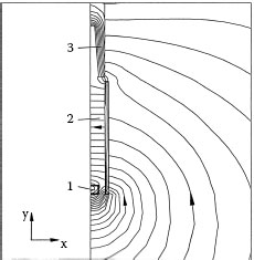
FIGURE 14.28
Increase of magnetic blowout force by ferromagnetic side plates: 1, arc; 2, ferromagnetic side plates; 3, ferromagnetic deion plates.
The trip (= release) system has to unlatch the operating mechanism in the case of prolonged overload (e.g., when a motor fails to start up) and short-circuit current, respectively. A typical current-time tripping characteristic of circuit-breakers is shown in Figure 14.29 [2]. The classical method uses a combination of a directly or indirectly heated bimetal element for the current-dependent overload region, and a magnet in the main current path (or fed through a current transformer) that acts instantaneously when its force exceeds a spring counter-force. As mentioned before, the latter can be combined with direct action on the moving contact in current-limiting breakers. Rigid noncurrent-limiting breakers may be provided with an additional adjustable time delay (marked 2″ in Figure 14.29) of several half cycles or even much longer for the short-circuit protection coordination with other circuit-breakers.
While in miniature circuit-breakers the above-mentioned classical trip devices will prevail for the nearer future, digital electronic solutions have been gaining more importance for larger circuit-breakers. Additional and more complex tripping criteria can be incorporated in the protection characteristic, free from the physical limits of the device, such as the heating time constant of the bimetal. The adaptation to different ratings and overload characteristics does not need different designs, the setting is simpler, and there are no mechanical and thermal tolerances that have to be compensated by individual adjustment of each device.
Electronic thermal overload trip solutions are widely spread in circuit breakers (MCCB) of large frame sizes and high current ratings. Meanwhile also smaller sized Coordinated Switching and Protective devices (CPS) [68] and Motor Protection Circuit Breakers (MPCB) use electronic motor protection circuits down to 4 A [69]. In addition, reduction of power loss and energy efficiency considerations lead to additional functions like power metering and communication. Also in conjunction with fast-acting arc-free current limiters (see 14.4.8), digital rapid fault and short circuit detection is of interest. In addition to the momentary current, its first time derivative [70], or even both the first and second derivatives [71,72] can form the tripping algorithm. Electronic trip systems are being introduced to detect low current arc faults, which would not trip the old style trip units. This is discussed in Chapter 15.
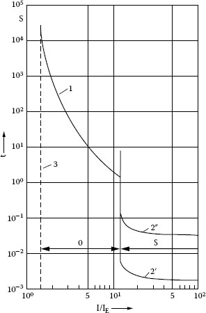
FIGURE 14.29
Trip characteristic for overload and short-circuit protection: 1, overload tripping; 2′, instantaneous short-circuit tripping; 2″, short-circuit tripping with short-time delay; 3, tripping limit for overload; O, overload region; S, short-circuit region.
14.4.5 Examples of Miniature Circuit-Breakers
Miniature circuit-breakers feature the basic attributes treated in Section 14.4.1, Section 14.4.2, Section 14.4.3, Section 14.4.4. They are used as single-phase units in large quantities in domestic installations, but also for cable or motor protection in industry. The following two examples represent two different philosophies.
The US types (example in Figure 14.30) are current zero switches from their general design, although there is always a current-limiting effect at 120 V system voltage. There is no need for extra-fast tripping and contact opening performance. The arc roots often stay on the contact tips that have to be erosion-resistant (typically WAg), the arc is elongated by contact opening and moderate magnetic blow-out within a simple arc chute. In the example shown, there is only one U-shaped floating iron lining surrounding the contact pieces (see also Section 14.3.3, Figure 14.12b). In other cases only two or three small deion splitter plates are used. Appropriate contact forces and wiping action on make and break help to remove the unavoidable tarnish films on W-containing materials. In this example, the spring acts as contact spring and as actuator spring for contact opening as well. Tripping on overcurrent occurs by a bimetal release and the tripping on short-circuit current occurs by a magnetic trip.
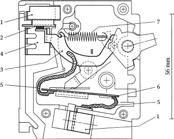
FIGURE 14.30
US type miniature circuit-breaker for 120 V, 10 kA (contacts closed): 1, terminals; 2, fixed contact piece; 3, moving contact piece; 4, U-shaped iron lining; 5, flexible connection; 6, bimetal trip system; 7, magnetic trip system.
The European miniature circuit-breakers (example in Figure 14.31) [73] act as current-limiters at short-circuit currents. The arc is quickly moved off the contacts by a magnetic field generated by a current loop and/or iron flux concentrators, commutated to arc runners, and directed to the arc chute. For this principle, the contact separation must occur extremely fast at current values still sufficiently low to ensure the arc motion necessary for voltage increase (see Section 14.1.4, Figure 14.5), and to enable limitation before the prospective current peak. The arc chute consists of a stack of around a dozen steel plates typically 1mm thick and 1mm apart. Their arc voltage lies at 350 V or higher and therefore exceeds the peak voltage in 230 V single-phase systems. The stack is often arranged so that the arc is subject to a 90° rotation during its motion. This helps to reduce back-commutations between the contacts. The contact points usually consist of AgC, mostly on the fixed contact, and of copper (often with a silver flash, mainly for tarnish protection) on the counter-contact. The graphite content (3–5% by weight) reduces weld forces and also helps to keep the contact resistance low after arcing. The trip system consists on the one hand of a solenoid that simultaneously acts as a kicker (Figure 14.27) to accelerate opening. On short circuit, tripping times below 1 ms and opening speeds up to 10 m/s can be reached by this. Total clearing times may lie well below 5 ms [15]. On the other hand, a directly heated bimetal element trips in the overcurrent range.
The contact materials used in circuit-breakers are summarized in the lower part of Table 14.3. Their ranking with respect to different stresses can be seen in Table 14.2. In the following discussion, only some special features of asymmetrical combinations that are used in circuit-breakers will be highlighted.
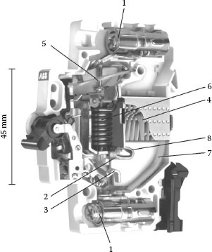
FIGURE 14.31
European type current-limiting miniature circuit-breaker for 230 V, 20 A, 10 kA [73]: 1, terminals; 2, fixed contact piece; 3, moving contact piece; 4, deion arc chute; 5, bimetal release; 6, magnetic release (solenoid kicker); 7, arc runner with flexible connection to moving contact; 8, arc runner connected to fixed contact.
As mentioned before, AgC is often used in European circuit-breakers because of its good anti-weld properties. Its main drawback, especially for current-limiting breakers, is the long dwell time. The following results of basic experiments show how nonsymmetrical combinations with other materials (AgNi 60/40, copper, or WAg) improve the situation. Figure 14.32 shows dwell times under conditions of miniature circuit-breakers [17]. The homogeneous metals Ag, Cu, AgCu own the shortest times; their anti-weld properties are however inferior. The heterogeneous compound material AgC shows by far the longest dwell times, silver/metal oxide compound materials and refractory metals (W, Mo) with silver lie in the middle. Nonsymmetrical combinations between Cu (Ag is similar) and the compound materials shorten the dwell time in all cases. In the same way, the dwell time of AgC is reduced by combination with any other material, whereby Ag and AgCu are best.
As already shown in Chapter 10, contact materials containing tungsten may have a tendency to high contact resistance. The same is true for copper in air. Figure 14.33 demonstrates the effect of AgC with results from a contact test machine, where always the same polarity was switched off [74,75]. Compared to the symmetrical arrangements, the 99.5% resistance values are considerably lower owing to the reducing atmosphere formed by the carbon content during arcing. A clear polarity influence can also be seen. In the case of random polarity the difference would even lie higher.
The effect of AgC in asymmetrical combination on the weld forces after making is demonstrated in Figure 14.34 [74,75]. The 99.5% value of copper lies nearly three times higher than that of either symmetrical AgC or AgC on only one side. The reason for the weld force reduction by the graphite content is believed to lie in the formation of a weak and spongy surface by gaseous reaction products between C and N2 as well as O2 from the air [76,77].
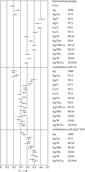
FIGURE 14.32
Dwell time of different contact material combinations under conditions of miniature circuit-breakers (current on contact separation 4 kA).
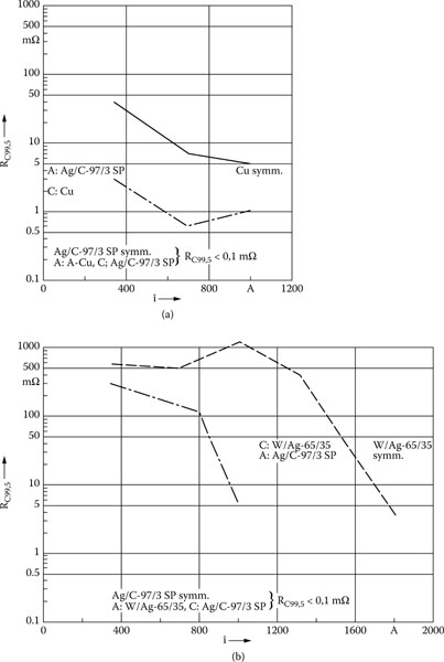
FIGURE 14.33
99.5% contact resistance vs. arc current for symmetrical and nonsymmetrical material combinations: (a) Ag/C against Cu; (b) Ag/C against W/Ag. Opposite polarity: 99.5%-resistance below 0.1 mΩ.
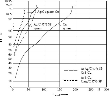
FIGURE 14.34
Statistical distribution of weld forces for symmetrical Cu and nonsymmetrical material combination Ag/C against Cu. I = 1300 A, 10 ms.
14.4.7 Special Requirements for DC Switching
Switching of dc circuits up to voltages of 1500 V is becoming more and more important for renewable energy, especially photovoltaics, electromobility, and micro-grids. In principle, arc quenching under dc functions like the current-limiting switching under ac: The arc voltage has to be raised above the system voltage. At low currents, where the self-magnetic forces to move the arc, and to pull it into splitter plates are much lower, the passage through current zero helps to interrupt in ac circuits, though the arc does not move, elongate, or split. In dc circuits, there are no current zeros, and additional measures have to be taken, especially for low currents. Those may be:
• Increased magnetic blast field
• Permanent magnets for blast field, yielding already higher forces at lower currents
• Additional generation of an air stream by a small pump coupled with the drive
• Splitter plates with especially narrow slots to improve arc splitting at low currents [78]
• Double break (see Figure 10.22)
• Hybrid arrangement of metallic contacts and electronic switching element [79]
14.4.8 Current Limitation by Principles Other than Deion Arc Chutes
There are many other principles than the most commonly used deion arc chutes that have been proposed and realized for the interruption of short-circuit currents. The classical ones are included in Figure 14.1a through d). Additionally some alternative methods, all current-limiting, have been investigated or are still under discussion. A few examples are given in the following subsections. Some of them drop out for environmental reasons.
14.4.8.1 Arcs Squeezed in Narrow Insulating Slots
The method of squeezing and elongating arcs between closely spaced insulating walls for voltage increase (Figure 14.1c) has been known for a long time. It needs high magnetic fields. A different way is to force the arc by a moving insulating screen into a narrow insulating slot [80,81]. Though the principle works well and the performance can be easily precalculated [82], it has not been used much so far. Problems lie in the erosion of insulating material, high pressure on the device’s casing, insulation failure from arc erosion and metal deposit, and strong plasma jet formation.
14.4.8.2 Reversible Phase Changes of Liquid or Low-Melting Metal
The so-called permanent power fuse uses a fuse conductor of sodium in a special ceramic enclosure, parallel to a resistor [20,83,84]. The resistance increase on melting, vaporizing, and plasma formation is used to limit the current. The circuit is finally opened by a circuit-breaker in series. After cooling down the fuse element is ready for use again. A commercial version was on the market, but could not establish itself. A liquid metal alloy GaInSn within a special enclosure with constrictions acts in a similar way, additionally supported by magnetic pinch forces in the constrictions [85]. Another idea suggested was to use the strong resistivity growth of highly pretensioned Hg (2000 bar), when energy from the short circuit current is fed into it [86].
14.4.8.3 Temperature-Dependent Ceramics or Polymers
Instead of metallic contacts and arcs temperature-dependent elements have been developed that limit the current by strongly increasing their resistivity when a certain temperature is exceeded [87,88,89,90,91,92]. Such materials are barium titanate and vanadium oxide ceramics, or polymers made conducting with carbon or metal fillers. In the last case, additionally to the volume nonlinearity, the contact interface plays an important role in the limiting effect at high currents [91,92]. In power circuits they must be used in conjunction with parallel resistors to consume the energy stored in the circuit inductance. Additionally, a mechanical switch is needed to interrupt the residual current. Polymer current limiters with Ampere-ratings or lower are widely used in electronic circuits, however, this principle has not found a break-through yet in power circuit protection.
14.4.8.4 Contact Resistance between Powder Grains
Since the contact resistance (constriction resistance) between grains of conducting powders depends on the force pressing them together, a setup has been studied with compressed TiB2 powder. Fast mechanical load release by magnetic or piezoelectric action can yield fast current-limiting switching [93].
The use of the transition from the superconducting state to normal conduction has been suggested and realized long ago. The discovery of high-temperature superconductors that do not need liquid helium but only liquid nitrogen for cooling has initiated new work on this subject worldwide [90]. The emphasis lies on current limiters in medium- and high-voltage systems. Owing to the high expenditure the application for low-voltage systems is unlikely, unless room-temperature superconductors are discovered.
14.5 Simulations of Low-Voltage Switching Devices
The rapid progress in computer technology on the hardware as well as on the software side has enabled more and more numerical simulations for principal studies and for design purposes as well, reducing gradually the necessary amount of experimental studies.
14.5.1 Simulation of Low-Voltage Arcs
14.5.1.1 General, Principle of Simulation
Arcs in low-voltage switching devices in air at atmospheric pressure are complex phenomena, where numerous plasma-physical and electromagnetic processes are closely coupled with each other. See, for example, [1] in Chapter 5, [45,46] in Chapter 9 and [94,95,96,97,98,99,100,101] in this Chapter. Figure 14.35 [102] represents a scheme of the processes in the arc column. Similarly, different coupled processes exist at the interface between the column and the electrodes.
The current density in the plasma generates ohmic heating and, together with the self-magnetic field from the arc plus the field generated from the external current path, brings forth magnetic forces. Both act on the gas flow and energy transport, and thus determine the temperature and pressure distribution. In turn, there results the local distribution of the electrical conductivity, as well as the other material parameters determining the flux flow or radiation behavior.
The numerical arc simulation, which should be in 3D owing to typical low-voltage arc chamber geometries, consists of the following components, which can be formulated as a system of 2nd order partial differential equations:
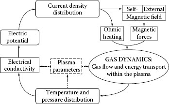
FIGURE 14.35
Scheme of coupled processes in the arc column.
Fluid dynamics of compressible gases (= plasma), so-called Navier-Stokes equations
The plasma is mostly treated in good approximation as a single continuum (fluid) in thermal equilibrium, to which the laws of fluid dynamics apply. Its transport properties depend on the local temperature and pressure. The Navier-Stokes equations consist of
• Mass balance
• Momentum balance
• Power balance (including radiation)
• Further transport equations, when further species such as metal vapor from the electrodes or gaseous decomposition products from the walls are to be modeled.
Maxwell equations (current flow, magnetic field)
It is mostly sufficient to treat both fields as time-stationary, leaving only the diffusive term in equation 14.4.
Further balance equations
For more complex radiation models, one or several additional transport equations may be necessary.
Though quite different in detail, all these equations follow the pattern of a general transport equation, which describes a physical quantity Φ transported at a flow speed :
(14.4) |
ρ density, ΓΦ diffusion coefficient, SΦ, source term.
The transported physical quantity Φ may stand for the speed components, the enthalpy, the electric potential, or the magnetic vector potential components.
Finite Element (FEM) and/or Finite Volume (FVM) software is used to solve this multi-physics problem, nowadays often in a combination of a standard FVM software package for fluid dynamics (e.g., FLUENT, CFX) with an electromagnetics FEM package (e.g., ANSYS).
The simulation of arcs in low-voltage switchgear requires special treatment of details, which can often be simplified in otherwise similar simulations of high-voltage switching arcs (in SF6) or welding arcs:
• The geometry of arc chutes requires 3D modeling.
• Since arc movement, that is, the permanent new-formation of arc spots in the forward direction along rails or similar electrodes is a necessary prerequisite for functioning of most switching devices, it must be included in the modeling method.
• The electrode regions (cathode and anode) play an important role in low-voltage switching devices. They strongly influence arc movement, formation of new arcs (especially arc splitting between metal plates), the arc voltage, and the power dissipated in the roots.
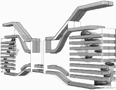
FIGURE 14.36
Example of simulated arcs in a stack of splitter plates [103].
Figure 14.36 depicts an example of simulated arcs in an arc chute with splitter plates from a motor protection circuit breaker [103]. Following are discussed some typical questions and challenges in modeling of low-voltage switching arcs.
14.5.1.2 Arc Roots on Cathode and Anode
As summarized in Sections 9.5.2 and 9.5.3 the processes in the cathode and anode falls, supplying the necessary charge carriers to the arc column and generating a considerable part of the arc voltage, are completely different from those in the column. They take place within a micrometer-scale rather than the millimeter or centimeter range of the arc chamber geometry. The conditions of charge carrier motion are partly free fall rather than random thermal movement, space charges exert a governing influence. There is no thermal equilibrium, but the temperatures of the electrons and of the heavy particles (ions and atoms) are quite different. To incorporate the cathode and anode spots directly into numerical arc simulations is therefore difficult and needs considerable simplifications. The following approaches have been taken:
• No arc root model, direct electrical and thermal contact between metal and plasma. Consequently the arc roots are completely neglected.
• Intermediate grid (3D or simplified as 1D) between metal and plasma in micrometer scale, solving for the balance equations of electron and ion currents, and the power balance in the fall regions [104,105,106]. This method is very laborious for an arrangement with a dozen or more splitter plates.
• Transfer or transition functions as boundary conditions between different zones, derived from more detailed theoretical considerations [105,107,108]
• A frequently used simple model is a thin intermediate layer or a transfer function on the boundary between metal and arc, modeling the essentially constant voltage drop across the cathode and anode falls in a static current density–voltage characteristic or an equivalent conductivity characteristic. Dissipated power density as the product between fall voltage and current density has to be split between the electrode and the plasma according to physically reasonable considerations. Figure 14.37 shows several variants of a characteristic, enabling some tuning. Such characteristics are able to model the continuous transition of the arc current from zero to 100%, when the arc is split up in series arcs on splitter plates [109,110,111]. An example of a simulated arc splitting process on a single metal plate is shown in Figure 14.38 [110]. It agrees in principle with experimental results, the arc bending around first, and the newly formed arc channel overlapping in time with the old one.
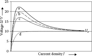
FIGURE 14.37
Variants of U – J characteristics of cathode or anode fall [110,111].
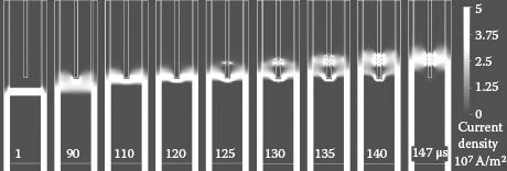
FIGURE 14.38
Simulated arc splitting process at a single metal plate. Characteristic b, current 1 kA RMS [110].
In high current arcs, a major part of the power generated in the arc is removed by radiation. Radiation is a very complex process which can hardly be incorporated into arc simulations in every detail. As a typical example, Figure 14.39 shows the absorption spectrum of air plasma which consists of numerous discrete lines and continuum as well [112]. A simplification often used is the net emission coefficient [113], which describes the difference between emitted and absorbed radiant power in a volume element. It is gained from data like Figure 14.39 by integration over the whole spectrum and over a characteristic arc volume, for example, a ball of 1-cm diameter. It can simply be used as a negative source term in the arc power balance, but is does not take into account that heat radiated in hotter regions is partly reabsorbed in colder regions, which is a diffusive process like thermal conduction. A different approach is to simplify the radiation completely by a diffusion coefficient [114,115]. This method neglects completely that a considerable part of the radiation leaves the volume unabsorbed and it yields too high temperatures. Many variants have been developed to model radiation better, but simplify the necessary processes of frequency and space integration. They are discussed elsewhere. In comparative simulations the so-called P1 models, which use additional transport equations either for the whole (“gray”) or several individual frequency bands (“nongray”) proved to show a good compromise between efficiency and precision [116,99].
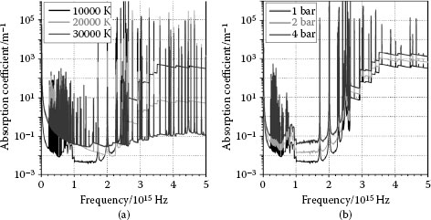
FIGURE 14.39
Absorption spectrum of air plasma [112, taken from 99] a) Variation of temperature, p = 1 bar b) Variation of pressure, T = 10,000 K.
14.5.1.4 Interaction between Arc and Electrode or Wall Material (Ablation)
The arc heats up the electrodes and the insulating chamber walls. They are partly vaporized and thermally decomposed. The gaseous constituents act back on the plasma properties and hence on the arc behavior. To model these processes correctly, one has to reproduce the heat balance in the solid, and the process of melting and/or vaporization in detail. For this the current density and, hence, the power density acting on the arc roots and radiating to the walls must be known, as well as details of the vaporization or decomposition process [117,118,119,120]. Since there are many unknowns, a simplified approach is often used, taking for example, an erosion rate depending on the local power density. It is also common to assume simple organic components such as H2, PA 66 or POM gas [95,99,121,122] as decomposition products from organic wall materials.
The strongly nonlinear temperature- and pressure-dependent data for plasma of any known composition can in principle be derived theoretically. For simulations they are usually taken as tabulated functions [123,124,125,126]. In comparison with pure air, metal vapors or organic vapors can modify the plasma properties and consequently the arc behavior. The mixing rules for different properties are different and not completely known. It is therefore common to simplify them in a reasonable way [99]. Following are some examples of the influence of admixtures:
• Metal vapor increases the electrical conductivity, especially shifts its onset to lower temperatures. This has a positive effect on the splitting into partial arcs [127]. On the other side the arc voltage is reduced, and the danger of unwanted back-commutations behind the arc is increased [99,128].
• Metal vapor increases the net emission coefficient of radiation [129,130].
• In agreement with experiments, outgassing plastics vapor (PA 66) cools and compresses the arc and speeds up arc motion and splitting. Furthermore the modified radiation properties increase emission from the hot arc core, as well as absorption near the cold walls [131].
Further data about the effect of metal admixtures on plasma data are given in [132,133].
14.5.1.6 Simplification by Porous Media
The last sections have shown that many very detailed physical processes have to be taken into account, if the simulation is required to be very close to reality. Still all of them need more or less simplifications. A different approach into the other direction is taken in [134,135]. Instead of modeling every single anode and cathode sheath in a chute with splitter plates, the whole stack is replaced by a continuum with anisotropic properties, where the electrical sheath characteristics are averaged. Also all other properties have to be averaged in a suitable way. It has been shown that this method is feasible in principle. Since this method is based on stronger simplifications, some adjustments with experiments are necessary.
14.5.2 Further simulations of contact and switching device behavior
Many more phases in the function of contacts and arcs in switching devices are nowadays simulated in the course of basic investigations or design studies. They are often combined to simulate a whole system or parts of it. Here, only a few keywords are summarized:
• Magnetic fields and forces [136].
• Heat balance of switchgear under nominal current and overcurrent load [137].
• Kinematics of actuators including impacts, magnetic forces, contact lift-off forces [137,138].
• Numerical models of contact morphology and contact resistance, utilization and advancement of Holm’s contact models by digital means [139,140].
• Thermal models of contacts under arcing influence, arc erosion, thermally induced mechanical stresses [117,118,119].
• Switching device—mechanics, arc voltage—in interaction with the surrounding electric network [141].
This is only a short overview of switching in vacuum. Special reference is given to the book “The Vacuum Interrupter: Theory, Design and Application” by Paul Slade [142].
This section first describes the design principle of vacuum interrupters and of low- and medium-voltage vacuum switching devices. The arc constriction at higher currents necessitates either radial magnetic fields to rotate the arc, or axial fields to keep it diffuse. Some switching results with these constellations are given. The contact material plays an outstanding role because the vacuum plasma is entirely fed from the contact metal. Its influence on current interruption under low-frequency and high-frequency conditions, as well as its influence on premature current cessation (chopping) are discussed.
The principle of interrupting ac currents by vacuum arcs (see Section 9.7.3) is mainly used in medium-voltage circuit-breakers, predominantly at voltage ratings to 40.5 kV. In this range the high electric strength of the vacuum at short gap distances shows most advantages over other quenching principles such as SF6 or oil. Vacuum breakers for voltages of 72 kV–145 kV are gradually encroaching on SF6 breakers, because of environmental concerns. Designers seem to be overcoming the problem of the disproportionately long gap distance necessary to withstand the voltage stress. The vacuum principle is furthermore applied in various contactor types for low-voltage (≤1 kV) and medium-voltage applications, as well as in medium-voltage load switches. The application in low-voltage circuit-breakers could not be established on a broad basis yet.
The active interrupter units of these devices are vacuum vessels shown in principle in Figure 14.40. They consist of a fixed and a movable contact, the latter fed into the vacuum vessel by means of a metal bellows. The contacts are especially shaped to generate magnetic fields (Section 14.6.3). One or more vapor shields act as condensation areas for the plasma and metal vapor produced during switching, and they serve to prevent the insulator from being coated with metal and to prevent other parts such as the bellows from being damaged [143,144].
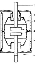
FIGURE 14.40
Principle of vacuum interrupter: 1, movable contact rod; 2, metal bellows; 3, vapor shield; 4, contacts; 5, glass or ceramic cylinder; 6, fixed contact rod.
Figure 14.41 depicts some major design variants of vacuum interrupters, (a) and (b) differ by the arrangement of the necessary insulator gap and the central vapor shield; (c) is a simpler design used in interrupters for lower voltages, where the shield is directly connected to one of the poles. The high vacuum (typically lower than 10−5 mbar = 10−3 Pa after fabrication) over a lifetime of decades requires special materials and manufacturing processes [143].
A typical example of a low-voltage vacuum contactor is shown in Figure 14.42 [45]; medium-voltage contactors are similar. The actuator principle is equivalent to the scheme of Figure 14.6c with a lever between the magnet and the interrupter. Differently from air break contactors they need only one contact gap per phase to interrupt the current. Typical contact strokes lie at a few millimeters; the opening and closing speeds are 1 ms−1 or lower.
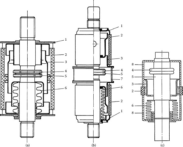
FIGURE 14.41
Different vacuum interrupter designs: (a) one insulator with floating shield inside; (b) two separate insulators with floating shield between; (c) LV contactor interrupter, shield connected to fixed contact. 1, metal cover; 2, insulator; 3, vapor shield; 4, fixed contact; 5, movable contact; 6, metal bellows; 7, metallic center ring; 8, housing.
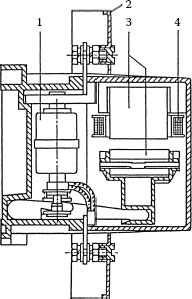
FIGURE 14.42
Low-voltage vacuum contactor: 1, vacuum interrupter; 2, terminal cover; 3, magnet core; 4, coil.
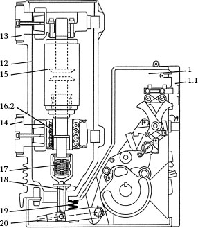
FIGURE 14.43
Medium-voltage vacuum circuit-breaker, poles mounted in insulator tube: 1, breaker mechanism housing; 1.1, front panel, removable; 12, insulating material pole tube; 13, upper breaker terminal; 14, lower breaker terminal; 15, vacuum interrupter; 16, roller contact; 17, contact pressure spring; 18, insulated coupling rod; 19, opening spring; 20 shift lever pair.
Figure 14.43 represents a medium-voltage vacuum circuit-breaker, whose actuator, as in low-voltage circuit-breakers, is spring-driven. In this special design the interrupter poles are arranged within tubes of epoxy resin [145]. Besides insulating these tubes take up the impact forces during switching and keep them off the interrupter vessel. A different variant is shown in Figure 14.44, where each interrupter pole is mounted on two post-type insulators [146]. In this case the forces are taken up by a separate insulating rod mounted parallel to the vacuum vessel. An alternative drive for vacuum circuit breakers uses a bi-stable electromagnet [147].
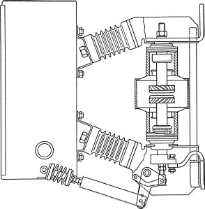
FIGURE 14.44
Medium-voltage vacuum circuit-breaker, poles mounted type insulators.
Depending on the rated voltage and breaking capacity, the final gap length usually lies at 1 cm and higher. For voltages over 50 kV several centimeters are necessary.
14.6.3 Recovery and the Influence of the Design
As discussed in Chapter 9, Section 9.7.3, the vacuum arc gap recovers rapidly if the arc has been staying diffuse or has gone diffuse again before current zero, and if the production of metal vapor that could be re-ionized under the influence of the transient recovery voltage (TRV) has ceased. On the other hand, vacuum arcs between plain electrodes become constricted and heavily melt large areas of the contact surface, when momentary currents of several kiloamperes are exceeded. The cooling time constants of these strongly vaporizing metal pools are large (millisecond range [148]) and may result in interruption failure after current zero.
There are two different methods used to overcome this problem. Both use magnetic fields generated by the current path through especially shaped contact structures:
• The first is to accept the arc constriction but to minimize its negative effect by forcing the arc to rotate instead of dwelling in one place. Thus, the arc energy is distributed evenly across the whole contact area. This is achieved by radial magnetic fields, by which, together with the axial current path, a magnet force F = I × B is exerted peripherally on the arc, see also Section 9.6.3. Figure 14.45a and b shows two typical examples of such structures [149]. Figure 14.45a represents so-called cup electrodes that have slanting slots in the outer cylinder, forming U- or V-shaped current paths, and a smooth contact ring without notches. The spiral electrodes, Figure 14.45b, are formed by appropriate slots in the contact plate. Again a U-shaped current loop is formed, acting on the arc in the sense of increasing the loop (compare Figure 14.2). In this case the arc has to jump across the slot when it reaches the tip of a spiral. This is not a serious problem.
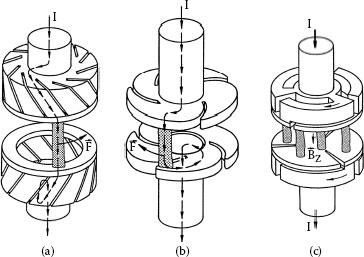
FIGURE 14.45
Vacuum contact structures for different magnetic fields: (a) cup contacts for radial field; (b) spiral contacts for radial field; (c) three thirds of a winding for axial field.
• The second way is to use axial magnetic fields that keep the arc diffuse to higher currents by forcing the charge carriers along the magnetic field lines (see Section 9.6.4). In addition to the even arc distribution, the arc voltage and thus the power transfer to the contacts and shield are lower [149,150,151,152]. A simple but space-consuming method to achieve this is an outside coil around the vacuum vessel [153]. Other solutions use more or less sophisticated constructions of the current path behind the contact plates [151] or they direct axial fields to the gap by ferromagnetic flux concentrators [153]. Figure 14.45c shows an example where the current path behind each electrode forms three thirds of a coil winding. In Figure 14.46, the distribution of the axial magnetic field component across the center plane of the contact gap, calculated by the three-dimensional finite element method (FEM), is shown [154]. The magnetic field is considerably enhanced by radial slots in the contact plate. On the one hand they improve the circular current flow necessary for the axial field, on the other they reduce eddy currents that cause a phase shift of the field against the current, with the consequence of a residual field at current zero [155,156]. This field reduces the effective mean free path of the charge carriers and may increase the reignition tendency. Figure 14.47 demonstrates the influence of radial slots by the FEM-simulated time-evolution of the center axial field without and with slots [154]. The higher field magnitude as well as the lower phase shift at current zero (t = 10 ms) becomes evident.
A comparison of interruption results with a demountable experimental vacuum chamber is given in Figure 14.48 for different contact configurations [152]. The “reignition voltage” plotted is either the breakdown voltage when the failure occurred in the first rising slope of the TRV, or the TRV peak in cases of successful interruptions or of late restrikes after the first peak. Because there is always a portion of reignitions after the first peak, the plot does not necessarily mean that the circuit-breaker will interrupt whenever the actual TRV peak stays below the curve of minimum reignition voltage, but it is a clear indication of the ranking of different configurations. While a sharp voltage decrease happens above 10 kA for the plain contacts and above 20 kA for the spiral contacts with moving constricted arc, the axial field contacts keep a higher voltage limit up to the highest current investigated. Results from postarc current measurements are shown in Figure 14.49 [152,154]. The lower postarc current of the axial field arrangement indicates less residual plasma around current zero at higher currents.
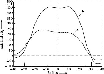
FIGURE 14.46
FEM-calculation of the local distribution of axial field at t = 5 ms for contacts like Figure 14.45c: (a) without slots; (b) with three radial slots in the contact plates. Diameter 62 mm, current shape: half sinewave 30 kA r.m.s.
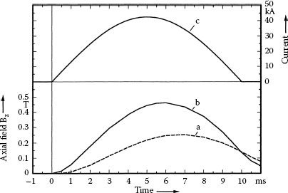
FIGURE 14.47
Simulated time evolution of axial field in the center for contacts like Figure 14.45c: (a) without slots; (b) with three radial slots in the contact plates; (c) current. Conditions as in Figure 14.46.
Of course the magnetic field configuration is not the only criterion determining the breaking capacity. Currently there are optimized interrupters of both principles on the market that do not substantially differ in size for the same high interruption capability [157]. Axial field contacts seem to have some advantages at the high-voltage end of the range.
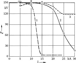
FIGURE 14.48
Lower boundary of reignition voltages for different contact arrangements vs. r.m.s. current. 50Hz, TRV frequency ≈ 20 kHz, TRV peak ≈ 160 kV; 1, plain cylinder; 2, spiral contacts; 3, axial field contacts; all contact diameters 60 mm, CuCr 75/25, gap distance at current zero 1 cm.
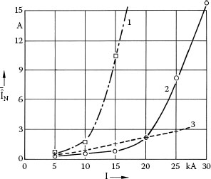
FIGURE 14.49
Postarc current maximum for different contact configurations vs. r.m.s. current: 1, plain cylinder; 2, spiral contacts; 3, axial field contacts; conditions similar to Figure 14.48.
Other factors influencing the current interruption are the same that determine the cold gap breakdown voltage, for example, smoothness of the contours of contacts and other parts stressed by the electric fields of the TRV, or cleanliness. The shape and size of the vapor shield also play an important role for the interruption behavior of vacuum breakers [158,159]. On the one hand a shield of larger diameter yields lower field strength of the partial gaps (contact–shield–contact). On the other hand the amount of residual plasma and therefore the intensity and duration of postarc current is increased by a wider shield. The shield potential follows the anode potential longer, which causes more uneven voltage distribution [159]. Also the heat capacity of the shield and its capability to take up the arc energy has an influence [158,159].
14.6.4 Contact Materials for Vacuum Interrupters and Their Influence on Switching
Because the medium in which switching takes place is entirely formed by the contact material and because it acts back on the quality of the vacuum, the requirements for contact materials in vacuum interrupters are even more complex than for other principles [143,144,160]. The major ones are:
• Low gas content and gettering effect to keep the vacuum during the whole service life.
• Low erosion rate. Eroded contacts cannot be replaced during service life.
• Low welding tendency and weld forces. Welding may be especially critical because
• There are no tarnish films, therefore tendency toward cold welding.
• There is no wiping contact action and no torsion to break up welds.
• There is a detrimental influence of welds on dielectric properties [161].
• Good interruption capability.
• Low chopping level.
• Low tendency to generate high-frequency transients.
• Low heat generation on current flow. As neither convection nor thermal conduction takes place within the vacuum, the heat can only leave the interrupter by thermal conduction through the contact rods.
• High electrical breakdown strength.
These requirements lead to consequences for some contact material properties:
• High electrical conductivity to reduce heat generation
• High thermal conductivity for good heat removal during continuous load and for fast electrode cooling after current zero
• Smooth surfaces after arcing
• Minimizing of particle formation on arcing which might lead to late restrikes [162,163]
The above requirements are partially contradictory, and the choice and development of contact materials is always a compromise.
The following groups of contact materials have been used for switching in vacuum [143,164,165,166,167]:
1. Materials produced by smelting:
a. Single-component materials, for example, pure copper, are scarcely used; they hardly meet the requirements.
b. Alloys such as copper with small additions of bismuth or tellurium for the reduction of weld tendency. These materials have been used in circuit-breakers by some manufacturers, but are now considered obsolete having been replaced almost universally by the Cu-Cr material.
2. Heterogeneous compound materials of two or more components with different melting and boiling points, mostly manufactured by sintering and/or infiltration techniques, such as
a. Combination of refractory component (W, WC) with lower-melting component, especially WCu and WCAg, for switches with a high number of switching operations but moderate breaking capacity (load break switches and contactors). Similar compounds like WAg or MoCu have also been developed and investigated, but are less common.
b. CuCr with compositions between 75/25% and 50/50% by weight. CuCr has proved optimum behavior in many respects for circuit-breakers: High breaking capacity, gettering effect, smooth surface after arcing with subsequent high electrical strength, moderate chopping current. To achieve special properties, further components such as high vapor pressure metals to influence the chopping and high frequency behavior (e.g., bismuth, antimony, zinc), are possible.
3. Other interesting suggestions concerned single-component materials or alloys with high vapor pressure to reduce the chopping current, for example, antimony, as solid depots in holes or grooves of erosion-resistant contact pieces (e.g., of molybdenum), so-called “low-chop” contacts [167,168,169,170]. Their interruption capacity is rather low, and they are not common.
In all cases, the manufacturing method and its parameters, size and distribution of the components, as well as minor additives or impurities, may decisively influence the performance of vacuum contact materials.
The following sections deal with the influence of contact material on the performance of vacuum arcs in the vicinity of current zero. Its influence on arc voltage, arc erosion, welding, contact resistance, and dielectric properties is treated elsewhere [168,171].
Figure 14.50 shows a simplified scheme of the coupled processes at cathode spots (see also Figure 9.46). Materials that own a high reluctance to re-establish these spots after current zero lead to a high breaking capacity. Therefore the electron emission and ionization parameters, the speed of cooling down, the readiness to vaporize or not, and the microstructure after arcing (smooth surface or sharp edges) play an important role.
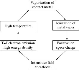
FIGURE 14.50
Simplified scheme of the processes in a vacuum cathode spot.
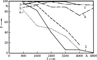
FIGURE 14.51
Frequency of successful interruptions vs. RMS current for different contact materials: 1, CuCr 75/25; 2, CuCr 33/67; 3, CuCrZn 65/24/11; 4, CuCrSb 68/24/8; 5, CuCrLi2O 76/23.6/0.4; 6, WCu 70/30; contact diameter 15 mm, distance 1.5 mm; 50 Hz, fTRV = 16–33 kHz, first TRV peak 35 kV.
Figure 14.51 summarizes results of model experiments with contacts of reduced size and different contact materials [172,173]. The percentage of successful interruptions is plotted versus the r.m.s. current. All results show the same pattern. While at low currents the interruption rate is equal or close to 100%, it decreases when a material-dependent limit is exceeded. CuCr 75/25 without third components shows a nearly 100% interruption rate over the whole range investigated, whereas the approximately opposite CuCr composition (33/67) leads to a high number of failures even at low currents. The addition of the high vapor pressure metal zinc (it forms brass together with copper) has no deteriorating effect under the investigated conditions, while antimony, also with high vapor pressure, already reduces the ability to interrupt. Small additions of alkali or alkali oxide (Li2O) result in considerably reduced breaking capacity, owing to the low work function and ionization potential. WCu also shows rather limited breaking capability. This is owing to agglomerates of tungsten that are formed by repeated arcing and that, owing to high melting and evaporation temperatures of tungsten, favor thermionic emission. Additionally it was found that the materials with the best performance had the smoothest surfaces after arcing, while the others showed sharp cracks and edges.
14.6.4.3 Interruption of High Frequency Transients
The fast recovery which enables high breaking capacity under line frequency conditons (50 or 60 Hz) can lead to unwanted voltage transients when the breaker successfully clears high frequency (HF) currents that are superimposed to the line frequency current under certain conditions ([142]; Section 5.3). This may occur when the gap distance at current zero is still too short to withstand the TRV. The reignition may initialize a HF current, and when the gap successfully clears in one of the HF current zero passages, a sequence of undesirable voltage escalations (“multiple reignitions,” “virtual chopping”) could start, depending on the circuit conditions. To avoid them, a poor interruption capability for HF currents would be ideal, while at the same time the high breaking capacity at line frequency should be unchanged [169,173,174,175,176].
Figure 14.52 summarizes statistical distributions of the HF reignition voltages of different contact materials [173,176]. For most materials at least two populations can be distinguished, representing different reignition mechanisms. One approaches the cold gap breakdown, the other is governed by the residual plasma. CuCr 75/25 without additives exhibits the highest values. Additions of low boiling point metals (Zn, Sb) yield a reduction but cannot really avoid HF current interruptions. As under line frequency conditions a higher chromium content increases the reignition tendency. WCu again shows a rather low tendency to interrupt, and alkaline additions yield practically zero reignition voltage. A comparison of HF and line frequency data shows that the contact materials behave rather synchronously, and that the ideal behavior described above can hardly be reached.
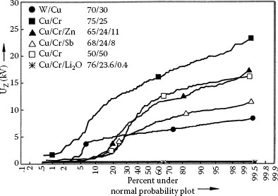
FIGURE 14.52
Statistical distribution of HF reignition voltages Uz for different contact materials after arcing with IPeak = 200 A, f = 200 kHz. Gap distance 0.1 mm, fTRV = 1.8 MHz.
In practice, today’s contact materials do not require special precautions against HF transients in most load cases. For especially critical load situations, surge protection measures help to suppress overvoltages ([142]; Section 5.3).
When the balance of charge carrier generation (Figure 14.50) is disturbed owing to lack of power input into the cathode region, the current may abruptly cease to flow (“chop”) before the natural current zero [168,169,177,178,142; Sections 2.3.3 and 3.2.6]. The simplest equivalent circuit to explain the consequences is like Figure 9.53, but with a rigid voltage source on the left side. The current Ich stored in the circuit inductance L at the moment of chopping commutates to the capacitance C′ which is always present in a circuit (e.g., winding capacitance of a motor) and initiates an oscillation. The maximum voltage appearing across the load is roughly , where is the surge impedance. Depending on the circuit parameters it may constitute a direct overvoltage problem or favor the conditions for the generation of multiple reignitions or virtual chopping (see “interruption of high frequency transient”). These events may be critical on switching low inductive currents. The chopping current of vacuum contact materials, which in turn depends on the composition as well as on the circuit parameters, should not be too high. As explained in detail in ([142]; Section 3.2.6), much attention was given to the phenomenon of current chopping during the early stages of vacuum interrupter development, initiated by experiences with the old copper-bismuth, but is considered not critical with today’s contact materials.

FIGURE 14.53
Chopping currents (average) of different heterogeneous contact materials. U = 400 V, f = 50 Hz, I = 45 A, Z = 1000 Ω.
Chopping currents show different statistical distributions depending on composition, materials homogeneity, and circuit parameters [178,179]. Figure 14.53 compares average chopping currents of different compound materials [168,169]. First it is remarkable that each of them has a lower chopping level than their pure constituents. While copper lies around 15 A and tungsten as well as chromium may chop at even higher currents, their mixtures lie in the area of 6 A. At least for WCu this may be explained by strong vaporization of copper while the refractory tungsten skeleton essentially stays unaffected. The depletion of individual components may change the chopping level gradually during service life. Several per cent of a metal with low boiling point and high vapor pressure, respectively, such as antimony or zinc, clearly reduce the chopping level, but not drastically. Against first expectations a small amount of additive with low work function and low ionization potential (lithium) strongly increases the chopping level. WCAg 60/40, which is not shown, has a chopping level of only 2 A under the conditions of Figure 14.53.
Figure 14.54 shows the chopping levels of concentrated low boiling point metals [169]. They lie much lower, but their use is restricted to low currents because of their poor breaking capability. Again calcium, an earth alkali metal with low boiling point, low work function, and low ionization potential, is an exception with very high values. The influence of these and other material parameters on the chopping level may be explained by a model of the power and particle flux balance of the cathode region taking into account the processes of Figure 14.50 [169].
14.6.5 Simulation of Arcs in Vacuum Interrupters
Similar to switching arcs for low voltage in air or for medium and high voltage in SF6, numerical simulations have gained more importance as study and design tools for vacuum interrupters. They have a great deal in common with those described in Section 14.5 for low voltage arcs in air, consisting of the mass, momentum, and power balances of the fluid, coupled with the current flow and magnetic fields. In contrast to plasmas at ambient or elevated pressure, there is no temperature equilibrium between the species of the plasma, and they need appropriate formulations to take this into account. Often, the cathode and anode regions are more or less simplified. To determine the production of metal vapor at the electrodes, which strongly influences the arc shape and behavior, the heat balance at the electrodes must also be considered. Those simulations help to better understand the arc behavior, and to optimize designs, for example, the local distribution of the axial magnetic field. Without going into details, few references are given:
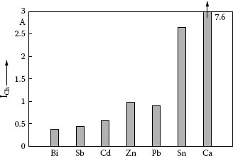
FIGURE 14.54
Chopping currents (average) of different metals with low boiling point. U = 400 V, f = 50 Hz, I = 45 A, Z = 1000 Ω.
• Axial magnetic fields [180,181,182,183]
• Transverse magnetic fields [184]
1. TE Browne Jr. Circuit Interruption, Theory and Techniques. New York: Marcel Dekker, 1984.
2. M Lindmayer. Schaltgeräte; Grundlagen, Aufbau, Wirkungsweise. Berlin: Springer-Verlag, 1987.
3. J Slepian. Theory of the deion circuit-breaker. Trans AIEE 48:523–527, 1929.
4. G Burkhard. Über das Lichtbogenverhalten in Löschblechkammern und deren Bemessung. Thesis TH Ilmenau, 1962.
5. A Lee, PG Slade. Molded-case low-voltage circuit-breakers. In ThE. Browne Jr (ed.) Circuit Interruption. Theory and Techniques. New York: Marcel Dekker, 1984, p 550.
6. A Erk, M Schmelzle. Grundlagen der Schaltgerätetechnik. Berlin: Springer-Verlag, 1974.
7. M Lindmayer, H Stammberger. Application of numerical field simulations for low-voltage switchgear. IEEE Trans CPMT 18(3):708–717, 1995.
8. M Lindmayer. Über die Vorgänge bei der Lichtbogenlöschung in kompakten Löschblechkammern bei Wechselströmen zwischen 2.5 und 8.5 kA. Thesis TU Braunschweig, 1972.
9. R Michal. Theoretical and experimental determination of the self-field of an arc. Proceedings of the 26th Holm Conference on Electrical Contacts, Chicago, 1980.
10. K-H. Schroder. Das Abbrandverhalten offnender Kontaktstiicke bei Beanspruchung durch magnetisch abgelenkte Starkstromlichtbogen. Thesis TU Braunschweig, 1967.
11. W Rieder. Interaction between magnet-blast arcs and contacts. Proceedings of the 28th Holm Conference on Electrical Contacts, Chicago, 1982.
12. M Lindmayer. The influence of contact materials and of chamber wall materials on the migration and the splitting of the arc in extinction chambers. IEEE Trans PHP 9:45–49, 1973.
13. D Amft. Über die Lichtbogenwanderung im Bereich geringer Geschwindigkeiten. 5 Int. Tagung über Elektrische Kontakte, Miinchen, 1970.
14. W Widmann. Arc commutation across a step or a gap in one of two parallel copper electrodes. Proceedings of the 13th Holm Conference on Electric Contact Phenomena, Chicago, 1984.
15. H Weichert. Lichtbogenwanderungs- und Kommutierungsvorgänge in strombegrenzenden Löschkammeranordnungen. Thesis TU Brauschweig, 1988.
16. H-W. Sudhölter. Über den zwischen divergierenden Elekroden wandernden Lichtbogen bei Strömen bis 90 000 A. Thesis TU Braunschweig, 1975.
17. N Behrens. Lichtbogenwanderung in Leitungsschutzschaltern. Thesis TU Braunschweig, 1980.
18. M Lindmayer. Simulation of stationary current-voltage characteristics and of back-commutation in rectangular arc channels. Proceedings of the 17th International Conference on Electrical Contacts, Nagoya, 1994.
19. K-H. Schröder. Kontaktverhalten and Schalten in der elektrischen Energietechnik-Grundlagen und Anwendungsbeispiele. 7. Seminar Kontaktverhalten und Schalten, Karlsruhe, 1983.
20. FW Kussy, JL Warren. Design Fundamentals for Low-voltage Distribution and Control. New York: Marcel Dekker, 1987.
21. M Poniatowski, K.-H. Schröder. Einfluß des Herstellverfahrens auf das Schaltverhalten von Kontaktwerkstoffen der Energietechnik. 7th International Conference on Electric Contacts, Paris, 1974, pp 38–45, 477–483.
22. W Böhm, N Behrens, M Lindmayer. The switching performance of an improved AgSnO2 contact material. Proceedings of the 27th Holm Conference on Electrical Contacts, Chicago, 1981.
23. Y-S. Shen, WD Cote, LJ Gould. A historic review of Ag-MeO materials. Proceedings of the 32nd IEEE Holm Conference on Electric Contact Phenomena, Boston, 1986.
24. W. Rieder. Silber/Metalloxyd-Werkstoffe für elektrische Kontakte. VDE-Fachbericht (VDE-Verlag Berlin) 42:65–81, 1991.
25. A Kraus, R Michal, KE Saeger. Schaltverhalten von Silber/Zinnoxid für Anwendungen im Bereich kleiner bis mittlerer Leistung. VDE-Fachbericht (VDE-Verlag Berlin) 42:83–87, 1991.
26. P Braumann, T Warwas. Analyse des Einschaltvorganges von Motorschaltern für die Entwicklung von Kontaktwerkstoffen. VDE-Fachbericht (VDE-Verlag Berlin) 42:47–57, 1991.
27. NEMA ICS 2-2000. Industrial control and systems controllers, contactors, and overload relays rated 600 Volts.
28. UL508, equivalent to CSA 22.2 No.14. Industrial control equipment.
29. UL489, equivalent to CSA 22.2 No. 5-09, Molded-case circuit breakers, molded-case switches, and circuit-breaker enclosures.
30. UL98, equivalent to CSA 22.2 No. 4. Enclosed and dead-front switches.
31. IEC 60947-4-1. Low-voltage switchgear and controlgear; Part 4-1: Electromechanical contactors and motor-starters. Equivalent: DIN VDE 0660. Teil 102, Niederspannungs-Schaltgeräte: Elektromechanische Schütze und Motorstarter.
32. Part -2: Circuit breakers
33. Part -3: Load switches
34. R Schnabel. Schütze nach NEMA und IEC: Philosophie der Realität. Elektrische Energie-Technik 31:8–10, 1986.
35. Sprecher + Schuh (Now Rockwell Automation). Various technical information brochures on contactors. Aarau, Switzerland.
36. M Lindmayer. Low voltage contactors: Design and materials selection considerations. Proceedings of the 16th International Conference on Electrical Contacts, Loughborough, 1992.
37. F Völker. Ein Verfahren zur Vorhersage des dynamischen Betriebsverhaltens von Schützen mit elektromagnetischem Antrieb. Thesis Universität/GH Duisburg, 1990.
38. AEG. ELSA, the contactor coil unit of the future. Technical brochure, Neumünster, 1990.
39. J Slepian. Extinction of an AC arc. Trans AIEE 47:1398–1407, 1928.
40. M Schmelzle. Grenzen der Selbstlöschung kurzer Lichtbogenstrecken bei Wechselstrombelastung. Thesis TH Braunschweig, 1968.
41. R Amsinck. Das Löschverhalten von Wechselstromlichtbögen in Schützen bei Ausnutzung der Säulenkühlung. Thesis TU Braunschweig, 1978.
42. N Reimann. Das Stromnulldurchgangs-Verhalten von Niederspannungs-Schaltlichtbögen unter Berücksichtigung von Kathodenschicht und dynamischer Lichtbogensäule. Thesis TU Braunschweig, 1986.
43. M Lindmayer. Effect of work function and ionization potential on the reignition voltage of Ag metal oxide contacts. Proceedings of the 26th Holm Conference on Electrical Contacts, Chicago, 1980.
44. A Takahashi, M Lindmayer. Reignition of arcs on double-break contacts. IEEE Trans CHMT 9:35–39, 1986.
45. Siemens. 3TF AC contactors. Technical brochure, Erlangen.
46. AEG. Low-voltage switchgear. Contactors and overload relays. Technical Brochure, Neumünster, 1988.
47. M Huck, A Kraus, R Michal, FJ Wagner. Silber/Zinnoxid in Relais und in kleinen Schaltgeräten. VDE-Fachbericht (VDE-Verlag, Berlin) 40:71–78, 1989.
48. P Braumann. Grenzen von Kontaktwerkstoffen der Energietechnik. VDE-Fachbericht, (VDE-Verlag, Berlin) 40:79–89, 1989.
49. P Braumann, J Lang. Kontaktverhalten von Ag-Metalloxiden für den Bereich höherer Ströme. VDE-Fachbericht (VDE-Verlag, Berlin) 42:89–94, 1991.
50. S Greitzke. Untersuchungen an Hybridschaltern. Thesis TU Braunschweig, 1988.
51. W Rieder, V Weichsler. Make erosion mechanism of Ag/CdO and Ag/SnO2 contacts. Proceedings of the 37th IEEE Holm Conference on Electrical Contacts, Chicago, 1991.
52. P Braumann, A Koffler, K.-H. Schröder. Analysis of the interrelation between mechanical and electrical phenomena during making operations of contacts. Proceedings of the 17th International Conference on Electrical Contacts, Nagoya, 1994.
53. K-H. Schröder. The future of electrical switching contacts under the influence of electronics. 34th IEEE Holm Conference on Electrical Contacts, San Francisco, 1988, pp 3–11.
54. G Friedrich. Hilfsschütze—eine überholte Technologie? Bonn: Klöckner-Moeller, 1990.
55. Th Schoepf. Interplay between electromechanical and solid state switching technologies for meeting cost, sustainability, and safety demands of various applications. 54th IEEE Holm Conference on Electrical Contacts, Orlando, 2008.
56. H Weichert. Halbleiter vs. Elektromechanik - Konkurrenz oder Ergänzung? Electrosuisse Fachtagung ITG-Hardware-Technology, Kontakte und Schaltelemente, Wintherthur, Switzerland 2010.
57. Siemens. 3RW Soft Starters. https://eb.automation.siemens.com/goos/catalog/Pages/ProductData.aspx?catalogRegion=WW&language=en&nodeid=10024029&tree=CatalogTree®ionUrl=/#topAnch&activetab=product&(04-03-2012)
58. Phoenix Contact. Contactron hybrid motor starters. http://www.phoenixcontact.de/produkte/54143_54157.htm (04-03-2012)
59. I Hackel. Mit dem Profibus gegen das Chaos. Siemens Drive & Control No 1:22–23, 1991.
60. D Amft, M Lindmayer. Schalt- und Schutzgeräte für Elektroantriebe. 12 Int. Fachtagung Industrielle Automatisierung—Automatisierte Antriebe, Chemnitz, 1993.
61. V Glocke. Verfahren zur Bereichserweiterung der Betriebsspannung für ein elektromagnetisches Schaltgerät. German Patent Application DE 4003 179 A1, 1990.
62. JA Bauer, DA Mueller, RT Basnett, JC Engel. Electromagnetic contactor with algorithm controlled closing system. US Patent 4.833.565, May 23, 1989.
63. H Meyer. Sanfteinschaltung bei Schützen mit Kontaktstücken aus AgSnO2. VDE-Fachbericht (VDE-Verlag, Berlin) 42:97, 1991.
64. IEC 60947–2: Low-voltage switchgear and controlgear; Part 2: circuit-breakers. Equivalent: DIN VDE 0660, Teil 101, Niederspannungs-Schaltgeräte; Teil 2: Leistungsschalter.
65. IEC 898: Circuit-breakers for overcurrent protection for household and similar installations. Equivalent: DIN VDE0641, Teil 11, Leitungsschutzschalter für den Haushalt und ähnliche Anwendungen.
66. EN 60934/VDE 0642, Geräteschutzschalter. Equivalent: IEC 934: Circuit-breakers for equipment.
67. R Holm. Electric Contacts. Berlin: Springer-Verlag, 1967.
68. IEC 60947-6-2. Multiple function equipment - Control and protective switching devices (or equipment)
69. Eaton. Motor protective circuit breakers PKE. http://www.eaton.eu/Europe/Electrical/ProductsServices/CircuitProtection/MotorProtectiveCircuitBreakers/MotorProtectiveCircuitBreakerPKE/index.htm (04-03.2012).
70. M Stege. Kurzschluss-Erkennungsalgoritzmen zum strombegrenzenden Schalten. PhD thesis TU Braunschweig, 1992.
71. T Mützel, F Berger M Anheuser. Methods of Early Short-Circuit Detection for Low-Voltage Systems. 54th IEEE Holm Conf. on Electrical Contacts, Orlando, 2008.
72. T Mützel. Verfahren der Kurzschlussfrüherkennung zur Verbesserung der strombegrenzenden Wirkung von Niederspannungs-Leistungsschaltern. PhD thesis TU Ilmenau, 2008.
73. ABB. Technische Daten. Sicherungsautomaten Baureihe S 200, S 200 M, S 200 P und S 280 UC. http://www05.abb.com/global/scot/scot209.nsf/veritydisplay/7368200c84b92309c12572eb0031cc69/$file/2CDC002071D0102.pdf (04-05-2012).
74. N Behrens, M Lindmayer. Der Einffuß von Kontaktwerkstoffen auf Lichtbogenverharrzeit, SchweiEkraft und Kontaktwiderstand unter Berücksichtigung unsymmetrischer Werkstoff-paarungen. Seminar Kontaktverhalten und Schalten, Karlsruhe, 1977.
75. M Lindmayer, K.-H. Schröder. The effect of unsymmetrical material combination on the contact and switching behavior. Proceedings of the 9th International Conference on Electric Contact Phenomena. Chicago, 1978.
76. R Michal, KE Saeger. Metallurgical aspects of silver-based contact materials for air-break switching devices for power engineering. IEEE Trans CHMT 12, 1989.
77. E Vinaricky. Das Abbrand und Schweißverhalten verschiedener Silber–Graphit–Kontaktwerkstoffe in unterschiedlichen Atmosphären. PhD thesis TU Wien, 1994.
78. V v.Döhlen. Lichtbogenverhalten beim Ausschalten von Gleichströmen. Experimente und Simulationen. PhD thesis TU Braunschweig, 1996.
79. M Wiersch. PV-Anlagen sicher trennen. ETZ S2: 26–29, 2011.
80. E Belbel, M Lauraire. A new breaking technology, independent from the contact material. Proceedings of the 13th International Conference on Electrical Contacts. Lausanne, 1986.
81. Z Huang, M Lindmayer. Current limiting switching by squeezing arcs into narrow insulating slots. IEEE Trans CHMT 15:160–165, 1992.
82. Z Huang, M Lindmayer. Switching arcs squeezed in rectangular insulating slots – scaling laws and comparison with measurements. European Trans on Electric Power 1:107–111, 1991.
83. T Ito, T Miyamoto, N Takano. Perminant power fuse self-recovering current limiting device. IEEE Summer Power Meeting, Paper No. 70 CP 601-PWR, July 1970.
84. T Itoh, T Miyamoto, Y Wada, T Mori, H Sasao. Design considerations on the permanent power fuse for a motor control center. IEEE Trans PAS, 92:1292–1297, 1973.
85. A Krätzschmer, F Berger, P Terhoven, S Rolle. Liquid metal current limiters. 20th Int. Conf. on Electrical Contacts, Stockholm, 2000.
86. HCW. Gundlach. A self-restoring current-limiting device. 3rd Int. Symp. on Switching Arc Phenomena, Lodz, Poland, 1977.
87. T Hansson, P-O Karlström. Device for motor and short-circuit protection. Int. Pat. Publication WO 91/12643, 1991.
88. FA Doljack. PolySwitch PTC devices—A new low-resistance conductive polymer-based PTC device for overcurrent protection. IEEE Trans CHMT 4:372–378, 1981.
89. Th Hansson. Polyäthylen-Stromwächter für den Kurzschlußschutz. ABB Technik, No 4: 35–38, 1992.
90. M Lindmayer, M Schubert. Current limitation by high temperature superconductors and by conducting polymers. Proceedings of the 5th International Conference on Electrical Fuses and their Applications, Ilmenau, 1995.
91. AR Duggal, LM Levinson. A novel high current density switching effect in electrically conductive polymer composite materials. J.Appl. Phys. 82: 5532–5539,1997.
92. A Wabner. Beitrag zur Kurzschlussstrombegrenzung mit leitfähigen Polymercompounds in der Niederspannungsebene. PhD thesis TU Chemnitz, 2001.
93. J Isberg, H Bernoff, L Liljestrand, L Jonsson, J Karlsson. A new powder based ac/dc switching technology. 20th Int. Conf. on Electrical Contacts, Stockholm, 2000.
94. F Karetta. Dreidimensionale Simulation wandernder Schaltlichtbögen. PhD thesis TU Braunschweig, 1998.
95. LZ Schlitz. Simulation of gas dynamics and electromagnetic processes in high-current arc plasmas. PhD thesis, Univ. of Wisconsin, Milwaukee, 1998.
96. A Hauser, DW Branston. Numerical simulation of a moving arc in 3D. 17th Int. Conf. on Gas Discharges and their Applications, Cardiff, 2008.
97. M Lindmayer. Lichtbogensimulation – Ein Überblick. VDE Fachbericht 65, VDE-Verlag Berlin, Offenbach, 2009.
98. M Anheuser, T Beckert, S Kosse. Electric arcs in switchgear – theory, numerical simulation and experiments. 19th Symp. on Physics of Switching Arc, Brno, Czech Republic, 2011.
99. Ch Rümpler. Lichtbogensimulation für Niederspannungsschaltgeräte. PhD thesis TU Ilmenau, 2009.
100. R Gati, J Ostrowski, D Piva. Comparison of arc simulations with experiments using a simplified geometry. VDE Fachbericht 67, VDE-Verlag Berlin, Offenbach, 2011.
101. H Stammberger, Th Daube, C Dehning, M Anheuser. Arc simulations in realistic low-voltage arcing chambers. 21st Int. Conf. on Electrical Contacts, Zürich, 2002.
102. F Karetta, M Lindmayer. Simulation of arc motion between divergent arc runners. 19th Int. Conf. on Electric Contact Phenomena, Nürnberg, Germany 1998; VDE Fachbericht 51, VDE-Verlag Berlin, Offenbach, 1998.
103. Ch Rümpler, A Zacharias. Simulation des Schaltlichtbogens am Beispiel eines Motor-schutzschalters. 24th CADFEM Users’ Meeting, Stuttgart, 2006.
104. P Zhu, JJ Lowke, R Morrow. A unified theory of free burning arcs, cathode sheaths and cathodes. J. Phys. D: Appl. Phys 25: 1221–1230, 1992.
105. A Kaddani. Modélisation 2D et 3D des arcs électriques dans l’argon à la pression atmosphérique avec la prise en compte du couplage thermique et électrique arc-électrodes et de l’influence des vapeurs métalliques. Thèse de doctorat de l’Université Pierre & Marie Curie Paris 6, 1995.
106. A Spille-Kohoff. Numerische Simulation des ChopArc Prozesses mit CFX-5. In: Final Report „ChopArc MSG-Lichtbogenschweißen für den Ultraleichtbau”. Fraunhofer IRB Verlag, Stuttgart 2005. http://www.cfx-berlin.de/de/entwicklung/choparc/download/cfx_040916.pdf (March 17, 2012).
107. JJ Lowke, R Morrow, J Haidar. A simplified unified theory of arcs and their electrodes. J. Phys. D: Appl. Phys. 30: 2033–2042, 1997.
108. J Wendelstorf. Ab Initio modeling of thermal plasma gas discharges (electric arcs). PhD thesis TU Braunschweig, 2000.
109. M Lindmayer, E Marzahn, A Mutzke, Th Rüther, M Springstubbe. The process of arc splitting between metal plates in low voltage arc chutes. 50th IEEE Holm Conf. on Electrical Contacts, Seattle, 2004.
110. A Mutzke, Th Rüther, M Kurrat, M Lindmayer, E-D. Wilkening. Modeling the arc splitting process in low-voltage arc chutes. 53rd IEEE Holm Conf. on Electrical Contacts, Pittsburgh, 2007.
111. A Mutzke. Lichtbogen-Simulation unter besonderer Berücksichtigung der Fußpunkte. PhD thesis TU Braunschweig, 2009.
112. V Aubrecht, M Bartlova, O Coufal. Radiation transfer in air thermal plasmas. 16th Int. Conf. on Gas Discharges and Their Applications, Xi’an, China, 2006.
113. RW Liebermann, JJ Lowke. Radiation Emission Coefficients for SF6 Arc Plasmas. J. Quant. Spectrosc. Radiat. Transfer 16: 253–264, 1976.
114. SV Dresvin (Ed.). Physics and Technology of Low-Temperature Plasmas. Ames, USA: Iowa State University Press, 1977.
115. R Siegel, JR Howell, J Lohrengel. Wärmeübertragung durch Strahlung, Teil 3. Berlin: Springer-Verlag, 1993.
116. C Lüders. Vergleich von Strahlungs- und Turbulenzmodellen zur Modellierung von Lichtbögen in SF6-Selbstblasleistungsschaltern. PhD thesis RWTH Aachen, 2005.
117. Ph Testé, T Leblanc, R Andlauer. An original method to assess the surface power density brought by an electric arc of short duration, and short electrode gap to the electrodes - Case of copper electrodes. 47th IEEE Holm Conference on Electrical Contacts, Montreal, 2001.
118. F Pons, M Cherkaoui. An electrical arc erosion model valid for high current: vaporization and splash erosion. 54th IEEE Holm Conference on Electrical Contacts, Orlando, 2008.
119. M Lindmayer. Simulation von Erwärmung, Abbrand und mechanischer Beanspruchung elektrischer Kontakte beim Schalten. VDE Fachbericht 65, VDE-Verlag Berlin, Offenbach, 2009.
120. M Anheuser, C Lüders. Numerical arc simulations for low voltage circuit breakers. 19th Symp. on Physics of Switching Arc, Brno, Czech Republic, 2009.
121. Ch Rümpler, H Stammberger, A Zacharias. Low–voltage arc simulation with out–gassing polymers. 57th IEEE Holm Conference on Electrical Contacts, Minneapolis, 2011.
122. Q Yang, M Rong, Y Wu. The simulation and experimental research on air arc plasma considering wall ablation in low-voltage circuit breakers. 23rd Int. Conf. on Electrical Contacts, Sendai, Japan, 2006.
123. RN Gupta, K.-P. Lee, RA Thompson, JM Yos. Calculations and curve fits of thermodynamic and transport properties for equilibrium air to 30000 K, Reference Publication 1260, NASA Langley Research Center, Hampton, VA, 1991.
124. AB Murphy. Transport coefficients of air, argon-air, nitrogen-air, and oxygen-air plasmas. Plasma Chemistry and Plasma Processing 15, 1995.
125. M Capitelli, G Colonna, C Gorse, AD D’Angola. Transport properties of high temperature air in local thermodynamic equilibrium. Eur. Phys. J. D 11: 279–289, 2000.
126. S Selle. Transportkoeffizienten ionisierter Spezies in reaktiven Strömungen. PhD thesis Univ. Heidelberg, 2002.
127. F Yang, M Rong, Y Wu, AB Murphy, J Pei, L Wang, W Liqiang, L Zengchao, L Yiying. Numerical analysis of the influence of splitter-plate erosion on an air arc in the quenching chamber of a low-voltage circuit breaker. J. Phys. D: Appl. Phys. 43, 2010.
128. M Lindmayer, A Mutzke, Th Rüther. Messungen und Simulation von Schaltlichtbögen in Löschblechkammern. VDE-Fachbericht 61, VDE Verlag Berlin, Offenbach, 2005.
129. Y Cressault, R Hannachi, Ph Teufet, A Gleizes. Influence of metallic vapours on thermal plasmas properties: Application to Air - Fe/Cu/Ag mixtures. XVI International Conference an Gas Discharges and their Applications, Xi’an, China, 2006.
130. V Aubrecht, M Bartlova, O Coufal. Radiative emission from air thermal plasmas with vapour of Cu or W. J. Phys. D: Appl. Phys. 43, 2010.
131. Ch Rümpler, H Stammberger, A Zacharias. Berücksichtigung gasender Kunststoffe bei der Simulation des Schaltlichtbogens. VDE-Fachbericht 67. VDE-Verlag ⋅ Berlin, Offenbach 2011.
132. Y Cressault, A Gleizes. Calculation of diffusion coefficients in air–metal thermal plasmas. J. Phys. D: Appl. Phys. 43, 2010.
133. AB Murphy. The effect of metal vapor in arc welding. J. Phys. D: Appl. Phys. 43, 2010.
134. J Riß, M Lindmayer, M Kurrat. Considerations to simplify the numerical gas flow simulation of low voltage arcs. 19th Symp. on Physics of Switching Arc, Brno, Czech Republic, 2011.
135. J Riß, M Lindmayer, M Kurrat. Simplification of the Arc Splitting Process in Numerical Gas Flow Simulations. XXth Int. Conf. on Electrical Contacts, Beijing, 2012.
136. H Stammberger. Magnetfeld- und Kraftberechnungen für strombegrenzende Niederspannungs-Schaltgeräte. PhD thesis TU Braunschweig, 1995.
137. F Barcikowski. Numerische Berechnungen zur Wärme- und Antriebsauslegung von Schaltgeräten. PhD thesis TU Braunschweig, 2003.
138. R Kalms. Simulation von Antrieben und Auslösern für Niederspannungsschaltgeräte. PhD thesis TU Braunschweig, 2000.
139. SV Angadi, WE Wilson, RL Jackson, GT Flowers, BI Rickett. A multi-physics Finite Element model of an electrical connector considering rough surface contact. 54th IEEE Holm Conf. on Electrical Contacts, Orlando, 2008.
140. P Lindholm. Numerical study of asperity distribution in an electrical contact. 57th IEEE Holm Conf. on Electrical Contacts, Minneapolis, 2011.
141. H Stammberger, H Pursch, A Zacharias, P Terhoeven. Simulation of the temporal behavior of circuit breakers and motor starters. 22nd Int. Conf. on Electrical Contacts, Seattle, 2004.
142. PG Slade. The Vacuum Interrupter - Theory, Design, and Application. Boca Raton: Taylor & Francis Group, 2008.
143. M Lindmayer, L Schiweck. Vakuumschalterentwicklung und damit verbundene Werstoff-Fragen. ETG-Fachtagung “Mit Energie in die Zukunft,” Nürnberg, 1986.
144. M Lindmayer. Das Vakuumschaltprinzip. Vakuum-Technik 36:101–108, 1987.
145. ABB Calor Emag. VD4 vacuum circuit-breaker. Instruction manual, Ratingen, 1993.
146. Siemens. Mittelspannung Vakuumschalttechnik, Leistungsschalter 3AF. Technical Brochure, Erlangen, 1991.
147. E Dullni. A vacuum circuit-breaker with permanent magnetic actuator for frequent operations. 18th Int. Symp. on Discharges and Electrical Insulation in Vacuum, Eindhoven, the Netherlands, 1998.
148. G Frind, JJ Caroll, CP Goody, EJ Tuohy. Recovery times of vacuum interrupters. IEEE Trans PAS 104:283–288, 1987.
149. Fr-W Behrens. Über den Einfluß der Elektrodengeometrie auf das Ausschaltverhalten von Vakuumleistungsschaltern. PhD thesis TU Braunschweig, 1984.
150. WGJ Rondeel. The vacuum arc in an axial magnetic field. J. Phys. D: Applied Phys. 8:934–942, 1975.
151. S Yanabu, E Kaneko, E Okumura, T Aioshi. Novel electrode structure of vacuum interrupter and its practical application. Proceedings of the IEEE PES Summer Meeting, Minneapolis, 1980.
152. F Unger-Weber, Wiederverfestigung des Hochstrom-Vakuumbogens bei höheren Spannungen. PhD thesis TU Braunschweig, 1988.
153. H Schellekens, K Lenstra, J Hilderink, J ter Hennepe, J Kamans. Axial magnetic field type vacuum circuit-breakers based on exterior coils and horse shoes. Proceedings of the 12th International Symposium on Discharges and Electrical Insulation in Vacuum. Shoresh, Israel, 1986.
154. B Fenski, M Lindmayer. Vacuum interrupters with axial field contacts—3D Finite Element simulations and switching experiments. Proceedings of the 17th International Symposium on Discharges and Electrical Insulation in Vacuum, Berkeley, California, 1996.
155. T Sohme, H Toda, E Kaneko, T Tamagawa, S Yanabu. Basic characteristics of axial magnetic field electrode for vacuum circuit-breakers. Proceedings of the International Symposium on Switching Arc Phenomena, Lodz, Poland, 1980.
156. Y Kurosawa, S Sugawara, Y Kawakubo, N Abe, H Tsuda. Vacuum circuit-breaker electrode generating multi-pole axial magentic field. IEEE PES Winter Meeting, New York, 1980.
157. RK Smith. Tests show the ability of vacuum circuit-breaker to interrupt fast transient recovery voltage rates of rise of transformer secondary faults. IEEE Trans PD 10:266–273, 1995.
158. PG Slade, RE Voshall. Effects of arc shield proximity to the electric contacts on the current interruption capability of vacuum interrupters. E&I 107:138–140, 1990.
159. V Biewendt. Einfluß der Schirm- und Kontaktgeometrie auf das Löschverhalten von Vakuumleistungsschaltern. PhD thesis TU Braunschweig, 1993.
160. PG Slade. Vacuum interrupters, the new technology for switching and protecting distribution circuits. IEEE Trans Industry Application, 33(6): 1501–1511, Nov/Dec. 1997.
161. W Widl. Contact welding and field emission breakdown in vacuum. ETZ-Archiv 4:12–17, 1982.
162. L Cranberg. The initiation of electrical breakdowns in vacuum. J. Applied. Phys. 23:518–522, 1952.
163. S Anders, B Jüttner, M Lindmayer, C Rusteberg, H Pursch, F Unger-Weber. Vacuum breakdown with microsecond delay time. IEEE Trans El 28:461–467, 1993.
164. PG Slade. Contact materials for vacuum interrupters. IEEE Trans PHP 10:43–47, 1974.
165. PG Slade. Advances in material development for high power vacuum interrupter contacts. IEEE Trans CPMT, part A 17(1):96–106, 1994.
166. H Kippenberg, W Kuhl, W Schlenk. Kontaktmaterial für Vakuumschalter. Siemens Energie und Automation 7:76, 1986.
167. E Vinaricky (Ed.). Elektrische Kontakte, Werkstoffe und ihre Anwendungen. Berlin, Heidelberg: Springer-Verlag, 2002.
168. U Reininghaus. Schaltverhalten unterschiedlicher Kontaktwerkstoffe im Vakuum. PhD thesis TU Braunschweig, 1983.
169. L Czarnecki. Einfluß des Kontaktwerkstoffes auf Stromabriß und Löschung des Vakuumbogens. PhD thesis TU Braunschweig, 1986.
170. D Sämann. Schaltverhalten von Vakuumkontaktstücken mit Antimon-Einlagerungen, PhD thesis TU Braunschweig, 1984.
171. K Fröhlich, HC Kärner, D König, M Lindmayer, K Möller, W Rieder. Fundamental research on vacuum interrupters at Technical Universities in Germany and Austria. IEEE Trans El 28:592–606, 1993.
172. D Heyn. Untersuchungen Zum Einfluß des Kontaktwerkstoffes auf das Löschverhalten im Vakuum. PhD thesis TU Braunschweig, 1990.
173. D Heyn, M Lindmayer, E-D. Wilkening. Effect of contact material on the extinction of vacuum arcs under line frequency and high frequency conditions. IEEE Trans CHMT 14:65–70, 1991.
174. J Panek, KG Fehrle. Overvoltage phenomena associated with virtual current chopping in three-phase circuits. IEEE Trans PAS 94:1317–1325, 1975.
175. J Helmer, M Lindmayer. Mathematical modeling of the high frequency behavior of vacuum interrupters and comparison with measured transients in power systems. Proceedings of the 17th International Symposium on Discharges and Electrical Insulation in Vacuum. Berkeley, 1996.
176. E-D. Wilkening. Vorgänge im Hochfrequenz-Stromnulldurchgang von Vakuumstrecken. Thesis TU Braunschweig, 1991.
177. GA Farrall. Current zero phenomena. In Vacuum Arcs, Theory and Application. (Editor: JM Lafferty) New York: Wiley, 1980, pp. 184–227.
178. G Philip. Untersuchungen über das statistische Verhalten der Abreißströme von Vakuumschaltern. PhD thesis TU Wien, 1984.
179. L Czarnecki, M Lindmayer. Influence of contact material properties on the behavior of vacuum arcs around current zero. Proceedings of the International Conference on Electrical Contacts, Electromechanical Components and their Applications, Nagoya, 1986.
180. E Schade, DL Shmelev. Numerical simulation of high-current vacuum arcs with an external axial magnetic field. IEEE Trans. Plasma Sci. 31: 890–901, 2003.
181. DL Shmelev. Low current vacuum arcs in strong axial magnetic field. 21st Int. Symp. on Discharges and Electrical Insulation in Vacuum, Yalta, Ukraine, 2004
182. W Hartmann, A Hauser, A Lawall, R Renz, N Wenzel. The 3D numerical simulation of a transient vacuum arc under realistic spatial AMF profiles. 14th Int. Symp. on Discharges and Electrical Insulation in Vacuum, Braunschweig, Germany, 2010
183. S Jia, L Zhang, L Wang, B Chen, Z Shi, W Sun. Numerical simulation of high-current vacuum arcs under axial magnetic fields with consideration of current density distribution at cathode. IEEE Trans. Plasma Sci. 39: 3233–3243, 2011.
184. T Delachaux, O Fritz, D Gentsch, E Schade, DL Shmelev. Simulation of a high current vacuum arc in a transverse magnetic field. IEEE Trans. Plasma Sci. 37: 1386–1392, 2009.