
Chapter 7
Protection of DERs
Raza Haider*
Abstract
This chapter gives a brief introduction of the different protection schemes in electrical power distribution system, integrated with distributed energy resources (DERs). The electrical power industry is now moving towards decentralization with the effective use of newly available renewable and micro energy resources. The protection system designed for high power and interfacing schemes is based on the direct coupling of rotary machines, i.e. synchronous or induction generators. Depending on the type of DER interface, the contribution to the fault current and accordingly the impact on protection will change. The chapter covers an overview of distribution system protection, the schemes for better protection, the coordination among protective devices, and the recent developments in the protective equipment. All the results are shown and briefly explained.
Keywords
distributed energy resources
protection
electrical power
generation
utilization
7.1. Introduction
Electric power systems are at their most popular since their invention and are now the most common constraint. They play a key role in technological reforms, infrastructure development, and economic growth. The well-linked system of electrical power distribution is the conventional one, that is, generation in bulk quantity, transmission at high voltage levels, and distribution via grid stations with the facility of end-user’s level voltage.
Experts worldwide are concerned over the grab of energy resources on the atmosphere and their regular supply in the coming future. In the past 10 years, a large fluctuation in oil prices has been recorded, and the scarcity of petroleum products prompted the energy experts to think of alternative and sustainable energy resources for a clean and green environment. Distributed energy resources (DERs) were promoted as an idea for instant electricity generation and connectivity to the main electric grid. A rapid growth of DERs has occurred as it provides clean power generation with less environmental impact, reliability assurance, and insertion of renewable energy sources for modern power scenario requirements [1].
The complexity of electrical power systems is mainly based on the smart and case sensitive protection schemes. A well-designed protection scheme is the backbone of any electrical system. DER is a recent idea that was developed for decentralizing the power system. The Electrical Power System industry comprises generation, transmission, and distribution, working closely with centralization. DER has brought new distribution technologies that not only give the opportunity to utilize the indigenous renewable energy resources at door steps but also make generation level small and less complex. It is a reliable system of distribution that changed the conventional model of power generation as promising and smart integrated system. There are numerous issues regarding fuel prices, genuine or artificial shortages, global warming, and increasing electricity need, which are big challenges for traditional power generation technologies to cope. DER with microgrids enable technologies to get more attention for their efficiency, durability, and improved reliability. There are some issues relating to DER protection which are being addressed and certain models have been developed to minimize and control power system disturbances.
The main purpose of DER is to utilize the energy resources that can serve at a cost of no transmission line, as the generation is close to the load center. The electrical power transmission system, with variable losses and high cost, has made DER a more reliable and promising option that shares load jamming on conventional utility and assists localized power generation. The DER system has the delicate intensity to control and can easily be handled by the distribution utilities.
The sustainable approach behind DER is to integrate it with the ongoing power system utilities by applying novel protective measures. The conventional distribution system is designed as a submissive network in which huge alternative energy penetration may cause bidirectional power flow, and as a result there are variations observed in voltage, current, or frequency. In addition, power system oscillations due to sudden fault currents could affect the protective apparatus. This chapter mainly focuses the different protection issues in DER, needs of protection, and reliable protection schemes.
The Institute of Electrical and Electronics Engineers (IEEE) P1547-2003 is a benchmark model for interconnecting DERs with conservative electrical power systems and it also provides guidelines for general interconnection of electric utility. This involves the response to abnormal conditions when functioning, power quality issues, and safety condition together with operation in utility grid connected and islanded mode [2]. Fig. 7.1 shows DER placement in an electrical power system network. This includes multiple power generation sources in a mode of bidirectional or islanded operation, and power flow coordination in a single network.

Figure 7.1 Distribution energy resource layout.
DERs became mainstream after advanced renewable energy technologies had been explored and implemented. Renewable energy equipment brings a helping hand for grid-integrated electric supply and benefits the suppliers, operators, as well the customers. Keeping environmental concerns in view, the conventional power generation technologies that use to produce more carbon is reduced. At present, researchers are working to suppress voltage fluctuations in renewable energy harnessing technologies because the frequency and voltage always fluctuate due to weather-dependent renewable energy resources. The energy storage devices with state-of-the-art technologies are gaining more importance to cope the fluctuation problems. These devices help for smooth voltage distribution and reduce the technical hurdles in distribution system [3,4]. The mode of transmission of energy through the main electric grid has now being changed by DERs and facilitating consumers to have flexible energy utilization.
DER integration to the main electric grid enforces major challenges in the protection systems. The conventional system of distribution is planned for radial distribution groups that contain feeders at one end with high fault currents. The fault currents always flow downstream in a radial system of distribution, from the utilization service towards the faulty point. Because of the single source of power generation, high fault currents are generated by the utilization service, triggering protective apparatus next to the feeder corridor. Therefore, despite the several advantages, there are many technological challenges behind control and protection mechanism for DERs [5].
Another issue is related to the number of units installed with DER, which connect the main electric grid in order to share supply line and the accessibility of adequate level of short-circuit current in the islanded operating mode. This level of DER may significantly fall down after a detachment from the main electrical grid while keeping express track. Actually, the working conditions of DERs continually vary because of the alternating energy resources, that is, wind, tidal, or solar, and intermittent load distinction. Such conditions may lead to overcurrent protection failure and will not guarantee any discriminating action for all possible faults. Thus it is necessary to check the selected setting for overcurrent protective relays that take into account the grid connectivity, transformed position, and the type and amount of power generation. The overcurrent relays (OCRs) and circuit breaker coordination, and sequential operating conditions at fast tracks are the challenges to be addressed.
7.2. Protection in distribution system
7.2.1. General protection
The prime objective of the power system protection is to ensure safe and reliable electrical power supply to consumers. The system is based on heavy duty and expensive equipment with high electrical power concentration, thus it should be of major concern.
In every system of electrical power protection, control of all electrical quantities is compulsory. Normally the values of voltage, current, and frequency should be under control and limiting these electrical quantities ensures the power system protection reliability.
The distributed energy protection system depends upon the mode of distribution, that is, radial, ring main, or network. The most commonly used system of distribution is the radial one that depends on the supply at one end through a main source. This system is normally very simple to operate and is generally employed with circuit breakers, fuses, and relays. But with the distributed generation injected to the main electricity system, it requires more attention, and can weaken the protection coordination. Therefore, a model and coordination has to be developed that can protect the overall system in a sound manner and allow fault diagnosis to be easily achieved.
Faults on overhead electrical power transmission or distribution systems are characterized as symmetrical and unsymmetrical. In an overhead system of transmission line the faults between any two phases of a three-phase system are rare, but bad weather conditions affect the line and give rise to faults. The most common faults occurring are single phase to ground, which are due to the insulator flashover and breakdown. In a distribution system, the overhead lines are subjected to different kinds of faults because the distance is closer to the utility end. Hence the overall protection scheme and the equipment operation should be linked with grid-integrated DERs. Transients and harmonics are rising as big problems in DERs that are already present in normal distribution systems. The harmonics are the distortion in voltage or current that occurs at a numeral multiple of the fundamental frequency, and the transients are the sudden changes occurred at distribution system depending upon the nature of load connected. One of the drawbacks of utilizing an alternating current (AC) source is that it produces transients and harmonics, because most of the loads in daily life are inductive in nature. There is much research going on to address this challenge and make transfer of AC supply constant and smooth.
Nowadays, electrical energy system engineering is going through a major transformation due to many alternative and renewable energy supplies and better quality of power distribution by the utility. This is going to be supportive in order to ignore disorder of manufacturing or other practices caused by voltage drop, swell, or distort conditions when a short circuit fault takes place in the distribution system [6].
The protection system of distribution network in general is used for power flows from the grid supply point to the downstream low voltage system. It is generally based on OCRs with preferred settings to pledge discrimination between upstream and downstream relays. The protection coordination should be arranged so that a fault on a downstream part must be cleared by the relaying system at the source end of the main feeder. At this moment, the operation of any other relaying system on an upstream part would result in a blackout and the system would be seriously affected [7].
There are several studies into DER protection, which are based on different protective algorithms. In one of the schemes, protection is provided by dividing the whole distribution network in different operating zones, which are known to be an islanding operation. A multilayer perceptron network is utilized for determining the faults by installing a computer-based relaying system. It is the most common neural network model because it gives the desired output mapping sets of all input data. This method is best suited to isolating system fault within a defined range and protecting rest part of the system [8].
In the integrated system of distribution, there are many cases that deal with different characteristics of overcurrent protection. This includes definite or inverse time and inverse definite minimum time characteristics. There are drawbacks of each overcurrent relaying protection, such as the time lag of the unknown nature of short circuits and coordination with the additional load. The protection scheme should be designed in manner that the fault clearing time is less and without causing disturbance for the end users [9]. When the DER is connected to the distribution substation, it makes the overall system complex because the new system will be having its own dynamics. Therefore, in order to synchronize DER with the ongoing distribution system, the corrective protection measures have to be taken. Furthermore, each protective device must be capable to differentiate this characteristic for all disturbing or faulty positions, the nature of faults, different load levels, and possible supportive supply design.
As shown in Fig. 7.2, a DER has to be connected to the ongoing power system bus. According to the fundamental principles of power system operation, the DER should have common electrical parameters for electric grid interconnection. The most important conditions that have to be fulfilled are:
1. The frequency of the DER and the existing system should be same, and
2. The voltages at the terminals of DER and the existing system should be same.

Figure 7.2 DER interconnection.
The DER interconnection is complex in the present scenario of main electric grid; it creates technical challenges in feeder design, where one or more generators connect to presented feeder. The areas of common concern are voltage regulation, relay desensitization, islanding, voltage flickers, transformer substitution, and resonant conditions.
The energy generating source, having some governor control mechanism, controls the real power supplied by the source to the electric grid whereas the field circuitries decide the amount of reactive power drawn from it. If the DER is connected to the existing system of power generation and running under lower frequency, this will make the DER consume electrical power instead of supplying it. Therefore, some control mechanism is important for the joint operation and control of DER and main electric grid. This can be achieved by a governor controller, which is a control mechanism with different set points to adjust the system frequency.
The prime objective of the utility companies is to supply electricity to consumers with protective standards and keeping the economical means in view. The protection of DER is achieved by protective relaying with the adaptive and new available schemes.
7.2.2. IEEE standards for protection
The recommended practice for protection of domestic, commercial, and industrial power systems given by the IEEE provides information regarding short circuit current, standard power system voltages, sensing device characteristics, and various interruptions in power systems. The general principles [10] for the relevant protection of DER specified in the IEEE standards are mentioned further.
7.2.2.1. Voltage requirements
The DER that has to be connected to the main electric grid will not be responsible for voltage fluctuation and may not cause variations in the area electric power system. Any mishandling could cause the severe unbalancing and affect the distribution grid auxiliary equipment operation.
7.2.2.2. The grounding
The grounding scheme should be designed in a manner that the connection to the main electric grid may not cause any over voltage that go beyond the rating of the equipment connected to the area of electrical power system. And the overall coordination of the ground-fault protection on the area may not be affected.
7.2.2.3. Synchronization
DER has brought new issues on the stability and the transient function of the main electric grid. The penetration of such resources into the grid may cause synchronization problems because the sudden detachment or reconnection gives rise to transients or harmonics. The voltage fluctuation at the point of common coupling around ±5% of the existing voltage level at the main electric grid is allowed for DER integration.
7.2.2.4. Energization area
The DERs, when integrated to the main electric grid, do not energize the area power system. The standard is about the DER units that stop to energize the area electrical power system for faults on the circuit to which they are connected. If a fault is detected in a circuit and has been de-energized by its protection system in order to clear the fault, there should be no fixed source on the circuit to energize it.
7.2.3. What to do under fault conditions
DER contains different generation units and capability of each unit to detect fault depends upon the technology utilized for generation and the nature of fault. The synchronous generators operating as a unit with DER produce fault currents during absolute periods of time because of their capability curve characteristics. The initial fault occurring can reach more than six times the generator full-load current and can decompose over a number of seconds under generator full-load current as the generator field disintegrates. Under such conditions, the voltage on the generator considerably comes down and helps to detect and analyze the fault. Different fault analysis techniques are employed based on the fault current and voltage sag on the synchronous generator. The commonly used techniques are OCRs with voltage control and voltage restraint with unlike inverse or definite time characteristics.
The voltage control OCR protection gives permanent sensitivity by building the set of overcurrent operating value relative to the applied input voltage. The OCR keeps the voltage under a desired value and controls it by under voltage factor. There are certain coordination difficulties caused by the magnitude of faults that continue for a long time because the sensitivity of the OCR has a preset value. The voltage restraint OCRs are adjusted at different sensitivity levels depending on the voltage sag. Normally, at 25% voltage the sensitivity is four times the one at the rated voltage. It provides better coordination and works as backup for differential relay [11].
For the induction generator operating with DER the fault current contribution depends on the declaration and the required time of fault current for relay to operate. The declaration of fault current in an induction generator depends upon the type, severity, and the means of reactive power compensation. The proper selection of these parameters makes the protection system efficient and the operation becomes smooth.
The DER with inverters behaves as intelligent active elements and, when connected to the main electric grid, cannot afford significant currents under outdoor fault conditions. These currents are usually not more than one and half times their rated load current. The generally applied fault-finding methods using overcurrent standards are not helpful in this case. Inverter-connected DERs rely on other techniques such as voltage deviation or frequency sensing to identify faults in the supply area of electrical power system. Whereas in case of external faults the behavior of the DER can be affected mostly because it is connected to the energy source that is dependent on different types of generator technology, which can supply current to a fault in their neighboring circuit or some other point of area electric power system. Such complications rise after DER integration to the main electric grid because of the dynamic behavior of different technological devices and load uncertainties.
7.2.4. Fault currents change
The DER sometimes works as microgrid, and the change in fault currents depend on the operation means. In DER integrated mode, the utilities contribute to microgrid fault currents and when operating in an islanded mode, the fault currents are less. With the power electronic devices the fault current adding capacity is limited to twice their rated currents. These lower fault currents do not trip the OCRs. Usually under normal conditions, the fault current decreases as the feeder impedance increases when fault point shifts downstream to feeder path. DER equipment, including synchronous and induction generators, contribute more to fault currents compared with DER with power electronic devices. This is because of the dynamic behavior of the machines, so the fault current paths could be different for the DER operation with electric grid or as an islanded mode. Such an arrangement will require different relay settings; the fixed relay settings under such condition might become unfeasible [12].
7.2.5. Smart protection
Voltage stability and coordination among protective devices with high DER penetration, flashing of renewable power output impacts on voltage regulation, and the controlling capability of DER with active and reactive components are the big challenges to cope with. Smart protection refers to the term that the DER integration to the main grid network should have its own protection scheme at the point of link, in order to transfer electrical power in a safe mode. The modern and projected advancements in power system apparatus, processors, and communication networks provide opportunities for pioneering utilities to develop power system organization, competence, and consistency.
Fault location isolation and service restoration (FLISR) application is one of the important developments in smart protection, which enables distributed utilities to implement advanced distribution applications. Fig. 7.3 shows the time line for fault investigation without FLISR, and the delay can be seen clearly. FLISR generates an immediate exchange plan for restarting sections of a distribution circuit that has been shut down as a result of an undying feeder fault. Once the exchange plan is generated, FLISR can mechanically implement the plan to reinstate service where feasible, generally in less than 1 min following the original fault incidence.

Figure 7.3 Time line for fault investigation without FLISR. (Source: Courtesy of PAC World.)
The FLISR application automatically senses that a fault has arisen and locates the fault between two intermediate switches. And then subject control commands to open the switches where likely to reinstate service to healthy sections of the feeder. This modern technology allows all of these actions to be completed without manual intervention [13].
In smart protection there are several control functions that include regulated power flow on feeders, regulated voltage at the interface of each DER, and load sharing when the system is islanded. It works as a chain reaction and reduces the additional complexity in operation, control, and protection system of the closed integrated loop. The general overview and operating conditions of FLISR are given further.
7.2.5.1. Fault detection
The operating control of FLISR is such set that it operates when a short circuit fault on upstream or downstream occurs. If the feeder becomes de-energized due to manual switching activities, the FLISR will not operate. Such an arrangement can be obtained by putting in more than one fault detectors to trigger FLISR function. Commonly a microprocessor-based control relay or intelligent electronic device (IED) is installed in substations to provide a signal to FLISR for operation.
7.2.5.2. Fault location
After fault detection, the fault segment on the feeder needs to be located. There are different sections on FLISR, which are enclosed by distantly controlled switches. These switches include the faulted circuit indicator (FCI) that determines if fault current has recently passed through the switch. This indicates if a fault is located further from the substation and uses the FCI status and feeder topology to determine the faulty zone.
7.2.5.3. Fault isolation
After fault location, FLISR issues control commands to open the switches desired to completely cut off the damaged segment of the feeder based on the fault location investigation. FLISR suspend all control actions until the routine reclosing sequence is completed and makes sure that reconfiguration of feeder by FLISR is performed. After performing all of the aforementioned checks the FLISR follows the permanent fault to operate.
7.2.5.4. Service restoration
This is the last action performed by FLISR, to isolate the damaged segment of the feeder. It attempts to reinstate the service to as many healthy segments of the feeder as possible using the normal source of supply to the feeder and offered backup that have standby capacity to carry additional load.
7.2.5.5. Power system stability
With the advent of DER, electrical power systems have been primarily impacted by stability and quality problems. The maloperations and change in protective device settings has dramatically reduced the reliability of DER. Voltage sags are the most significant power system stability problems since the application of the power electronics equipment. The controlling and monitoring devices like programmable logic controller, supervisory control and data acquisition, or automatic voltage regulator are becoming very much sensitive to voltage sags as the complexity of the equipment enhancing [14]. A high share of DER is supporting new technologies to wipe away conventional boundaries and demand in a more practical complexity. Every new operational element adding to the distribution system will lead to associated fluctuation. Like many, DERs are dependent on weather conditions; under normal weather, power generation will be up to the required level. However, any change in weather will at once create a large jerk in the area electric power system and the supply into a given line will drop. Such changing weather conditions may cause voltage variations and create stability problems. Even the change in demand response or real-time charging interacts with programmed home controls to deal with an oversupply of energy on the grid. The fall in prices boosts up energy consumption at domestic and industrial levels and, as a result, a sudden surge in demand is developed [15]. These kinds of issues greatly influence the distribution system in general and the other interconnected systems in particular. Thus the distribution system has to be more imperatively situational based that should consider the load and control dynamics.
7.3. Power system disturbances
A broad classification of power system disturbances that might occur and cause potential impact on the system behaviors and the equipments is described in this section. The normal operating conditions and the smooth flow of electrical power makes the system stable.
7.3.1. Power quality issues
There are certain power quality issues that need to be addressed and remedies that have to be taken to strengthen the overall power system and increase the life of equipments. Any disturbance in the electrical power system is caused due to the change in the system parameters that affects basic electrical quantities. Some of the quality issues are mentioned further.
7.3.1.1. Voltage behavioral changes
The voltage is an important electrical quantity that generates pressure to make a smooth flow of the current. Any change in this quantity rather than the desired value leads to some unfavorable conditions like voltage dips, voltage surges, overvoltages, undervoltages, voltage fluctuation, voltage imbalance, or short and long voltage interruptions. The voltage dips are exercised due to the local and remote faults in the area of electrical power system with maximum inductive loading and the continuous switching operation of large loads. This impact is found on the sensitive protective equipment in the form of tripping.
Voltage surges are produced due to the capacitive switching, phase faults, and sudden switch off of heavy loads. The surges form high voltage penetration, thus the sensitive equipment operates at once and damages the insulation and windings of machines. The change in voltage is due to the system voltage regulation or heavy network loading, this might impact the equipment dependent on constant steady state voltage. The imbalance in voltage is due to unbalance loads and impedances, which create overheating in motors and generators and mostly interrupt three-phase power operations.
7.3.1.2. Power frequency variations
Power and frequency variations in an electric supply system are mainly due to the extreme loading conditions and loss of generation. The frequency of power system depends on the active power balance and needs to remain constant at different operating conditions. Any change in load affects frequencies in the entire region and tie-line power exchange among regions. Such variations impact on motoring operations and power electronic equipments.
7.3.1.3. Harmonics and transients
The harmonics in power system equipment due to the nonlinearity of transformer core have been always the point of research and interest has increased over past years with the rapid change and modernization in power system devices. Heavy inductive loading in the industries, rectifier equipment, and the source of conventional power generation made this a main power quality problem. Harmonics create maloperation of sensitive power system equipments. The transients are aperiodic current waveforms that flow in a circuit for a very short duration following an electromagnetic disturbance due to various reasons.
7.3.2. Faults
The faults refer to the unwanted or stern variation in the state of voltages or currents under standard working conditions. At normal stages, the electrical power system equipment carries standard voltages and currents that make power system operation secure. However, under abnormal conditions the unwanted signals, known or unknown, damage the power system equipment and stop supply.
Thus to have safe and secure operation, different and technically sound protection schemes are employed that comprise relays, reclosers, circuit breakers, isolators, and other switchgear equipment. In general, electrical power system disturbances are classified into two broad categories, symmetrical and the unsymmetrical faults.
7.3.2.1. Symmetrical faults
A fault in an electrical system is a failure that impedes the standard values of voltage and current. Symmetrical three-phase faults are roughly 8–10 %, and cause severe power system disturbances. The currents which flow in unlike parts of the power system instantly after the event of the fault fluctuate from those flowing a few cycles afterward just prior to the circuit breakers operate and open the both sides of faulty line.
The current at this stage is totally different from the currents that flowed under steady state conditions. This can be continued if the faulty line is not disengaged from the line by the efficient use of circuit breakers. Circuit breakers are normally dependent upon the value of the current flowing after the occurrence of fault and the interruption. The analysis of the three-phase fault is carried out on a per phase basis and the information regarding is taken from the switchgear equipment.
7.3.2.2. Unsymmetrical faults
The faults that cause imbalance between any two phases are known as unsymmetrical faults. In electrical power system, 80–90% faults are of unsymmetrical type and cause severe unbalancing in the power system operation. Before the occurrence of an unsymmetrical fault, the system is balanced and the positive sequence network is dynamic. As the fault occurs, the sequential networks automatically connect through the faulty line. Fig. 7.4 shows the symmetrical and unsymmetrical fault waveforms.

Figure 7.4 Symmetrical and asymmetrical waveforms.
These faults can be calculated by applying a bus impedance matrix composed of positive or negative sequence impedances. The method of positive sequence network is applied to determine voltage and current under symmetrical fault conditions. For unsymmetrical faults, negative and zero sequence networks are applied.
Faults in the power system may occur due to certain internal and external conditions that influence directly on power system operations. The reasons behind some of the fault origin conditions are discussed further.
7.3.2.3. Surrounding weather
The fault mostly depends on the condition of the atmospheric weather. Wind, heavy rain, humidity, coastal wind effects on bare conductor transmission lines, ice topping, etc, interrupt the power system continuity and reliability.
7.3.2.4. Equipment
The electrical equipment has to be protected for the all mishaps. As most severe faults in electrical systems are short circuits, the cause could be improper handling, insulation breakdown, or poor cabling. Heavy currents flow through electrical equipments during short circuit fault that could damage or weaken the supply equipment.
7.3.2.5. Mishandling
Mishandling also leads to electrical faults. Such human error could put the lives of the personnel handling the system in danger. The improper rating of the device, loose connections, or poor servicing leads to such problems.
7.3.2.6. Flashover
Flashover in a power line is caused due to the stress on insulators. The corona effect in the transmission line occurs because of ionization in the air. As air is not a perfect insulator, the ionization makes surrounding air conducting and, as a result, the flashover or spark causes the insulators breakdown.
7.3.3. Consequences of electric faults
7.3.3.1. Flow of overcurrent
In an electrical circuit the overcurrent flow produces very low impedance path resulting heavy current being drawn. The current sensing devices trip the circuit at once, any delay could cause loss of insulation or apparatus.
7.3.3.2. Threat for operator
The fault in a system could cause danger for the personnel handling and it depends upon the magnitude of the fault current. Therefore, safety measures and advanced training are essential for the operator handling electrical power system apparatus.
7.3.3.3. Loss of apparatus
The electrical system apparatus can burn completely if the protection equipment could not operate well timed. It is mandatory to keep overall protection coordination smooth to save the devices and the individuals.
7.3.3.4. Effect on healthy systems
Electrical faults may affect a healthy system connection or interconnected circuits of a network to the faulty point.
7.3.3.5. Fire risk
Severe short circuits in a transmission or distribution system due to lightning, heavy winds, or snowfall could cause flashover and sparks that lead extreme fires.
7.3.4. Application based three-phase fault analysis
The circuit shown in Fig. 7.5 has three-phase supply, star-delta connected transformer, and the other fault analyzing devices carrying a three-phase load. The temporary switches connected create temporary and permanent faults. By pressing the switching button, one creates a temporary fault and the 555 timer arrangement trips the line and restores electric supply back to load. By pressing the switch button more than one time, the circuit will create permanent faults thus disconnecting the circuit from the supply line, and the relay arrangement will shut down the system. The distribution protection system also works in the same pattern [16].

7.4. Impact of DER on protection system
A DER can be considered as small generating station ready to be integrated with the regular electric grid. Generally the DER can be considered as renewable energy or a conventional small-scale generation system, in order to mix share in central power system. There are two options, connect the DER to electric grid or use it in an islanded mode. During any such operation, some diversity is observed that the energy can flow in either track when protection system is sensing and the commonly used radial system of distribution has no bidirectional flows. The low capacity units used in a DER system may affect the distribution system in a number of ways. The overall performance, reliability, and stability may be put in danger if additional protection devices are not installed with proper coordination [17].
DER installation changes the conventional practice of distribution scheduling and engineering by escalating the range and density. Even many conventional rules of thumb and guidelines might not remain valid.
In a conventional electrical network, the electrical power flows in one direction only, that is, from the feeding transformers to the load end. But the DER installed at distribution substations may lead the electrical power flow back and forth. This is because the conventional distribution system protection is not planned to work with DER and different power generator capabilities with changed voltage profile. In total, the DER deals with all power generation voltages including renewable and nonrenewable, which contribute differently during a fault.
All generators give rise to the fault currents during any power system disturbance. But synchronous generators are the main cause of such disturbances because of the field excitation and stability problems. Another challenge for the offered protection of distribution networks is DER integration. Since DER is generally coupled with distribution system, the new connection of a generating source can redistribute the source fault current on the feeder circuits causing loss of relay coordination and possible over voltage [18].
In many countries, most loads are designed to supply radial loads, and a DER running on an islanding mode will make the system more complicated. For the uninterruptable utilities the fault clearing time is of worth importance and they need the fastest fault recovery time, which is impossible if the DER is running in islanding mode.
7.4.1. Protection failure
The trouble when integrating DER with the presented electrical power network is that distribution systems are intended as a passive network, that is, carrying the power unidirectional from the central generation at high voltage and then downstream to the load centers at low voltage.
There are two different ways the protection system might fail to operate correctly. One is the mal-trip (without cause eliminates a nonfaulted element) and the other is fail-to-trip (unable to eliminate a faulted element) as shown in Fig. 7.6.

Figure 7.6 Mal-trip and fail-to-trip (CIRED 2007).
A mal-trip can occur when a DER unit feeds an upstream fault, which is initiated from any of the DER units. Such a condition may disobey the edge of overcurrent protection at the definite feeder, and will disconnect it with the system unnecessarily.
Fail-to-trip occurs for downstream faults and in this case the fault current is mainly composed of the current originated from the DER unit. Therefore, the fault current through the overcurrent protection remains passive and the faulty feeder will not be disconnected from the system [19].
7.4.2. Hosting capacity
Let us consider a network without integration of DER that can be modified to consider integration with DER. In order to establish the maximum allowed penetration of DER into an existing network, different indices can be formulated, which are the base for determining hosting capacity. In addition, corresponding to varying degrees of modification, the varying amount of DER can be accepted. The hosting capacity recognizes the degree of DER in the electrical power grid that can be received without putting the reliability or quality of power systems in danger [20]. The performance of the system can be seen from the hosting capacity definition. The estimation of the hosting capacity is repeated for each different phenomenon in power system operation and design and it depends on system parameters including structure of network or type of DER.
One more significant performance condition is that the DER unit must have a selective protection system with the other protections in the network. The selectivity constraint means that the DER should be linked in with the system as long as possible and if selectivity is not a prerequisite, the system and its adjustment will likely be kept simpler. This will allow the DER to be detached without taking into account other protection devices in the network [20].
7.4.3. Loss of coordination
In normal operating conditions, the protective devices correspond in a way that the main protection works before the backup can take some action. The DER integration to the ongoing power system increases the chance of short circuit fault. Depending on the original protection coordination settings along with the size, location, and type of DER, an uncoordinated condition may be acceptable. In such conditions, the backup protection operates before the main, and this results tripping of some loads.
In order to make operation stable, some modifications in coordination between the protective devices and DER should be made. Again it depends on the source of generation being protected because the grid interfacing technology differs for every source, like power electronic converters, induction generators, and synchronous machines.
Here we have developed a generalized method that sets the penetration limit of DER in terms of range, position, and equipment from loss of coordination viewpoint [21]. The procedures involved are summarized in following steps and a flow chart is given in Fig. 7.7.
1. In a given system, first define the different coordination paths. A coordination path can be defined as a set of protective devices positioned along a circuit path starting from the main feeder breaker to the most downstream protective device. Most of the fuses selected, which are lateral or sublateral, should be similar and lead to a limited number of different coordination paths. A single coordination path might represent many laterals utilizing the same types of fuses.
2. Construction of coordination charts and organizational study of different protection paths may lead towards better operation.
3. The least short circuit current at which the loss of coordination may occur among all protective coordination paths is to be examined. This current may be the junction between coordination curves of two successive protection devices. In a case where there is no junction between the coordination curves, the minimum current may not continue living. Such a condition will not limit the installed DER to breach the system coordination and work efficiently.
4. Describe the contestant points at which the DER may be installed. The penetration limit will be calculated for these specific points. These contestant points may be obtained from a planning study to resolve the finest location of DER to reduce system losses and improve the voltage profile, or it might be stated by the customer.
5. Here the simulation is applied at first contestant point and the capacity of any one of the DER and its interfacing transformer is increased gradually. It will be continued till reaching the minimum short circuit current for the loss of coordination and the specific DER size will be recorded. It should be noted that increasing the size of DER and its interfacing transformer inherently increases the short circuit mega volt-ampere (MVA) capacity of the combined DG/transformer set.
6. Keep on doing the same practice as described in step 5 for other contestant points. This will help in estimation DG impedance estimation using its rating.
7. Tabulate the results.
8. The same procedures could be repeated by altering the DER technology. Consider the cases of synchronous, inverter-based or induction generators, and then repeat steps 5 to 7 by tabulating individual results.

Figure 7.7 A generalized method to assess the loss of coordination. (Source: CETC-Varennes 2007.)
7.4.4. Protection issues of DER
Low voltage distribution systems including DER are divided into limited protective regions which are enclosed by a network or the equipment consisting of transformers, generators, buses, or loads. The well-known criteria 3S provides the requirements for basic design of a distribution protection system and holds good for directional, distance, and differential protection schemes. The abbreviation 3S stands for selectivity, sensitivity, and speed of protection system. Sensitivity refers to the ability to recognize an anomalous state that exceeds a small threshold value. The selectivity makes the protection system target oriented that disconnects only the faulted part of the system at any abnormal condition in order to minimize fault implications. Speed is important for any protection scheme, and the devices should respond to power system disturbances in the fastest possible time in order to avoid risk and keep stability check [22].
Fig. 7.8 shows different protection zones of medium voltage (MV) and low voltage (LV) line connected with circuit breakers (CB). CB 0 and CB 1 are protecting the MV and LV lines. The DER generation (labeled G) and the load are connected to the system through switch board.

Figure 7.8 Protection zones of MV and LV circuit breakers.
If a fault occurs between the line and the main electric grid, the MV protection system clears the fault. However, in case of sensitive loads the DER has to be isolated by the system circuit breaker (CB2) as fast as possible. The required time could be 70–80 μs. Also the DER has to be isolated from the main electric grid by CB1 if the MV protection is not operated in the required time. A fault detected by an OCR can be challenging in the case of a DER consisting of power electronics equipment because they have fixed fault current restrictions.
Power electronics devices are capable of supplying a smaller rated current to a fault but the rotary machines specifically designed to supply high fault currents. The fault current depends on the sources of short circuit electrical power. The grid electrical power has generally higher short circuit strikes compared to small DER integrated to normal distribution system. As a result, the fault current sensed by protection relays is less than the fault current sensed when the distribution system is connected to transmission line electric grid in an islanded mode [23]. But still such numbers are lower than a short-circuit current supplied by the main electric grid. In this case a directional OCR with circuit breaker is only practical solution if current is used for the fault finding. Therefore, the setting has to be constantly supervised and modified when DER generation experience changes depending upon the source of generation.
Fig. 7.9 shows a DER monitoring and control system, which is functionally composed of the components with different operational modes. The boxes shown within the interconnection system are associated with power equipment functions whereas the circles represent monitoring and control functions. The power equipment functions change the electrical energy from one form to another in order to make it compatible to use. Like the storage devices provide a direct current (DC) source or the microturbines give power at high frequency. The quality issues are also checked by the conditioning devices connected with power equipment to supply a clean AC power [24].

Figure 7.9 DER monitoring and control.
The protection and control monitors the common point of coupling with the overall flow of electrical power supplied by DER. The main function of these blocks is to disconnect the DER connected with main electric grid under abnormalities. By following the IEEE standards, which provides an opportunity for developing procedures and maintenance support, risk can be minimized.
7.5. Protection schemes for distribution systems with DER
A distribution system with DER integration requires a modified protection system because of the many challenges caused by small scale generation in the form of DER. Unusual changes occur during transition from interconnected to islanded network operation. DER applications are reliant on variable primary energy resource, which modify the system working conditions and put down the efficiency of the conventional protection system all through faults occurring.
Presently, many electrical power research institutes, companies, and energy managers are working together for the reliable deployment of DER technology with grid integration. According to recent reports, US military bases are presently looking for consistent and protected energy resources, as these most popular bases are powered by public electrical grids, which in some occasion lead to as many as 300 power outages per year [25].
These disruptions deteriorate the military and other executive institution motivation and create certain protection issues. Reliance on conventional energy supplies may be inadequate to perform important function by these institutions, as well as to other emergency support service agencies, hospitals, and networking data centers. The control and protection hardware are being advanced to permit the supplying of the consumers in island mode as well.
7.5.1. Islanded operation
Islanding is a state in which a part of power system consisting of one or more power sources and load is separated from the rest of the system. Such a state will remain active as long as the DER is capable to meet the load demand. Because of the sudden disconnection from the main supply, the coordination among the protective devices may be lost and lead to vulnerability. Due to the aforementioned facts and associated problems the DER disconnection is preferred if an islanding state is observed.
Islanded operation (IO) can be intentional or unintentional depending upon the condition of the system. For unintentional IO it is planned in advance whereas the system and equipment is designed to deal with the situation. The DER is then capable of controlling the voltage and frequency in IO. An intentional IO regularly exists in manufacturing plants where the procedure has additional energy that can be used to produce electrical power [26].
There are two approaches to deal with islanding operation. The first one deals with the inverter control modes and the other is the synchronous generator control modes [27]. In inverter control mode the DERs have an inverter as a generator interface and they can operate either as a current source or as a voltage source. Normally the voltage source inverter (VSI), with added control loops, can make current control source if required. Due to the voltage and frequency references all the inverters can be operated in active and reactive power (known as PQ) mode.
The VSI controls the magnitude as well the phase of output voltage and the inductor circuit determines the flow of active and reactive power from the DER. Fig. 7.10 shows the basic inverter interfaced generation system. Here the vector connection between the voltage of the inverter, V, and the generation voltage, E, along with the reactor, L, determines the flow of active and reactive power form the DER to the main electrical grid [28].

Figure 7.10 Inverter mode.
In synchronous generator control mode the frequency of the DER is maintained tightly; however, following a disturbance the frequency may change quickly due to the low inertia present in DER. Therefore, the control of the main electric grid is very important in order to protect the frequency of the DER during islanded operation [29].
7.5.2. The protection equipment for DER networks
There is a large selection of equipment used to protect the DER networks. The rigorous type of protection used depends upon the scheme of the system and the level of the voltage. Fault clearance is a critical job in power system network. If we interrupt the circuit directly when fault occurs, it reduces the substantial smash up to the power system apparatus and also assets. The DER protection is not dependent on a precise standard but the resource availability, the pattern of scheme, and the utility infrastructure indicates the state of action. The most commonly used devices for DER protection are:
1. OCRs;
2. Reclosers;
3. Sectionalizers; and
4. Fuses.
7.5.2.1. Overcurrent relays
The relays give excellent protection for generators, transformers, and buses. These are not really suitable for feeders and transmission line protection. This is because the current transformer (CT) would need to be located at either end of the line and the secondary leads conducted over the relatively long distances. This is expensive and, more importantly, the impedance of the secondary conductor could give rise to serious inaccuracies. In a relaying system, the differential principle is used for different applications. The very common form of feeder protection is to protect it from overcurrent. For example, if a fault occurred in a feeder, it would give rise to the overcurrent in the line. An OCR connected closer to the breaker would detect the fault and could be set to open the breaker. The standard device number for an instantaneous OCR is 50.
The principle of operation of this type OCR is simple, the CT may use the current in the primary line and the CT secondary passes this current through the coil of electromagnet. The resulting magnetic force pulls the hunched armature that is a clapper against a restraining spring. If the current input to the relay is above the preset pick up level, then the relay contacts will close and energize the tripping circuit. The pickup level can be adjusted by taps on the coil and also by adjusting spring tension.
Another type of instantaneous OCR is the plunging type. In this case the electromagnet pulls the plunger up against the force of gravity. Again the pickup level can be preset by adjusting the taps and also by adjusting the position of the core. When current accedes the pickup level, the instantaneous relay will operate within about 50 ms, that is, about 3 cycles, and energize the tripping circuit to open its associated breakers.
In order to avoid fault consequences the operating pickup must be set to a very high level. This would be adequate for preprotection of severe faults that could affect the power system stability.
One of the recent advancements in OCR for power distribution includes the protection, automation, and control (PAC) system with more than 25 elements added for quick response and advanced-level protection. Fig. 7.11 shows the PAC system model, which provides feeder protection as well bay control along with eight setting profiles. With microprocessor based control and power quality monitoring system, certain effects of sag, swell, transients, and harmonics are detected and recorded.

The protection against low-level faults is achieved by time OCR of standard No. 51. This is a typical type time OCR, and its main components are electromagnet, the operating coil, the rotating disc, pin contacts, and time dial. The secondary current from the CT is passed through the operating coil, which is wound around the central leg of the electromagnet. It sets up this magnetic circuit, the flux passes through the magnetic disc and then returns through the disc again to the outer legs of the electromagnet. In this condition the disc will not rotate as these two fluxes are in phase. However, by placing a shorting coil at one outer leg, a phase displacement occurs and the flux here will now lag the inner one and cause the disc to rotate.
The disc is normally held stationary by a retaining spring. Only when the sufficient current passing through the operating coils, the disc will start to move. That is the pickup level, and the magnitude of the current in the operating coil is proportional to the primary current along the feeder, which is being protected. Therefore, the greater the primary current, the greater the operating current will be, and the greater the flux, the faster the disc will rotate. Similarly, the higher the level of the fault current, the quicker the operation of the relay will be. These conditions will finally force the circuit breaker to operate.
7.5.2.2. Reclosers
Reclosers are protective devices used to recognize phase to phase, and phase to ground-faults under overcurrent condition. It breaks off the line if the state of overcurrent persists after a programmed instance, and recloses mechanically as the fault is removed. It will remain open after a fixed number of actions, if the fault is still in the line, and will close upon complete isolation of the fault. In overhead system distribution lines 70–80 % of the faults are of momentary nature and last a few seconds or cycles.
Hence, the reclosers, with its opening/closing characteristic, protect a supply circuit being left out of service for momentary faults. Normally, the reclosers are intended to have three open/close operations at maximum and, after these, a last open operation to lock out the succession. One added ultimate operation by instruction manual means is generally permitted. The counting means record operations of the phase or ground-fault units which can also be commenced by externally controlled devices when suitable contact ways are available.
There is a variety of solid dielectric reclosers designed to provide overcurrent protection for distribution system. The structure is composed of epoxy summarized vacuum disrupter attached through a impel rod to a high-speed magnetic activator. Such an arrangement provides excellent insulation properties and secured void-free structure.
The operating time versus current curve of reclosers normally includes three curves, one is the fastest and the other two are delayed. The new recloser devices have a microprocessor-based control, which helps an operator to produce any curve that suits the coordination requirements for both ground and phase faults. This permits encoding of the individuality to understand the consumer’s precise needs without changing the apparatus.
Synchronization with other safety devices is significant in order to guarantee that, when a fault arises, a minimal part of the circuit is detached to reduce interruption of supplies to consumers. Normally, the time feature and the progression of action of the recloser are chosen to organize the instrument upstream towards the supply.
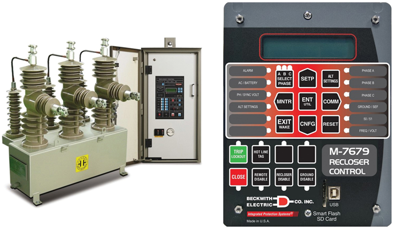
At present the new generation recloser device, known as Recloser Control M-7679, is compatible and independent pole with more than 30 elements for best protection, maximal automation, and communication technologies are inserted. Fig. 7.12 shows the recloser and its control mechanism. The device operates with all other protective components in a coordinated way and functions promptly with any abnormality.
7.5.2.3. Sectionalizers
Sectionalizes automatically cut off faulted segments of distributed lines prior to an upstream circuit breaker or a recloser interruption. Such a device is normally installed downstream of a recloser. While sectionalizes have no capacity to rupture fault current, so they are used in distribution protection with a supporting device that has fault current breaking capacity. The sectionalizers tally the number of events of the reclosers throughout electrical disturbances, and the number of recloser openings is preselected. Upon reaching the preselected value, the sectionalizer opens and isolates the faulty section of a line. This allows the recloser to shut and reinstate provisions to those regions, which are free of faults. If the fault is momentary, the operating instrument of the sectionalizer is reset.
Sectionalizers operate with hydraulic or electronic mechanism and are constructed to operate for both single and three phase systems. The sectionalizers are coordinated easily with other protective devices as they do not have time–current characteristics. It also brings an added step of protection without any coordination to the protective scheme. Fig. 7.13 shows a three-phase sectionalizer with control mechanism and sectioning rods.

7.5.2.4. Fuses
Fuses are the simplest and most commonly used overcurrent protection device. This is a primary device with slim wire enclosed in a covering or glass which joins two metal parts. It holds a fusing element subjected to the flow of current and blows when the current exceeds a preset value. The physical substitute of a wire is necessary if it blows out due to any abnormal state.
The correct function of a fuse usually depends upon the opening of circuit immediately after the high current interventions. This happens due to the heating effect of high current on the fusing element. However, the majority of fuses used in distribution systems function on the discharge code explicitly having a tube to detain the arc by the inside enclosed with deionizing fiber. In the occurrence of a fault, the interior fiber is excited when the fusible element melts and produces deionizing gases which amass in the tube.
When the fault occurs, the high current flow produces an arc which is compressed and expelled out of the tube. The escape of gas from the nail clippings of the tube causes the particles that maintain the arc to be debarred. Similalry, the arc is quenched when current reaches zero.
This is a primary protecting device with slim wire enclosed in a covering or glass which joins two metal parts. The wire melts while extreme current flows in a circuit. There are different types of fuses that depend on the voltage at which it is to work. The occurrence of deionizing gases and the commotion within the tube makes sure that the fault current is not established again after the current passes through zero point. The function zone is limited by two factors, the lower limit is based on the minimum time required for fusing of the element and the upper limit is determined by the maximum total time that the fuse takes to clear the fault. There are different international standards to categorize fuses according to their electrical characteristics. The commonly known categories are voltage and current ratings, time–current relationships, developed features, and some other considerations.
7.5.3. Recent technological trends in DER protection
The organization and control of distribution networks is becoming advanced and changing due the use of new digital protective relay technologies. Broadly, deployment of supervisory control systems that gather grid data within a few seconds is too periodic to expose many of the power system disturbances that cause tripping of relaying circuits.
7.5.3.1. DER protection characteristics
The electricity infrastructure is mainly divided into three zones, generation, transmission, and distribution, whereas the protection is mandatory for all the three zones. The goal of all utility companies is to deliver electricity in a protected, consistent, and efficient way. The relaying system in a protection zone makes the overall system of electricity safe and secure. The protective relaying system comprises current transformers, circuit breakers, and the relays.
The job of the DER protection system is to sense and react to all emerging faults with minimum or no loss to the consumers and equipment. The relaying system does not operate at normal power system operations and also does not limit the capability of a system to carry load currents. However, in electrical systems no device works under ideal conditions, and if the equipment is trying to accomplish some of the objectives described previously it may compromise on others. The limit of this concession is the criterion used to determine positions for fault-interrupting devices, and the sensitivity and working speed of the fault sensing devices. Such different relaying systems are applied in distribution system for overcurrent protection.
7.5.3.2. Overcurrent protection scheme
The overcurrent protection scheme is used to protect the distribution lines of electric grids integrated with DER. This protection scheme is further classified into two categories, the phase overcurrent protection and the ground overcurrent protection. The relays used in such schemes could be directional (operating for in-front events) and nondirectional (will operate for all) depending upon the mode of distribution. The nondirectional relays are mostly used for radial distribution systems.
In all the cases, the feeder protection starts at the electric grid with feeder control mechanism (a breaker or recloser). Reclosers are usually prepared with the inverse time overcurrent device that senses the faults and sends signal to the breaker, and then after a predetermined setback, it operates by reclosing the breaker. All the protective devices should be in sound coordination with the upstream and downstream links. The upstream link is the high voltage transformers, and the downstream are the protective equipments.
Fig. 7.14 shows the schematic arrangement for overcurrent protection of DER with coordinated protection. The generation is fed to the transformer via isolator switch, and the output power from transformer passing the OCR is supplied to end-users.

Figure 7.14 Overcurrent protection scheme for DER.
7.5.3.3. Fuse operating scheme
Utility companies generally apply two strategies in distribution lines for fuse operating schemes, which are known as fuse-saving and fuse-blowing. The fuse-saving strategy under operation benefits both the company and the consumers. In this scheme, the service is restored automatically and the technical handling is no more required for replacing the fuse. However, one of the drawbacks of fuse-saving schemes is the limited coordination at high currents, as it just coordinates with the next device to trip and functions at the same time. This results in temporary electrical power failure, thus the utility companies have now replaced this scheme with fuse-blowing.
Fuse-blowing schemes are used to limit the total reclosing cycle for the main feeder. This is employed for sensitive loads in distribution feeders, where considerable interruption occurs if the line is momentarily de-energized. One more application of this scheme is commercial and urban load centers where the number of reclosing cycles could result damage to equipments or individuals [30].
7.5.3.4. Voltage control scheme
A direct voltage control method without the inner current control loop can provide a faster and a more robust performance; however, it is unable to limit the current in the DER unit during abnormal conditions. Thus, a fault condition can either trip out the DER unit or damage its power electronic components. A voltage-controlled–distributed energy resource (VC–DER) unit is also prone to dynamic overload conditions since it lacks the capacity to rapidly limit the output power. This is due to the inherent characteristics of the controlling devices.
The overload protection scheme limits the output power of DER. This scheme identifies overload conditions based on voltage measurements and limits the output power by assigning suitable voltages to the terminals of the interface voltage-sourced converter (VSC) of the DER unit. Fig. 7.15 shows a VC–DER unit, characterized by a DC voltage source, a VSC, and a series RL filter. The unit is interfaced to the DER microgrids at the point of connection through a step-up transformer. The block denoted by “Remainder of Microgrid” comprises voltage and power-controlled DER units and other components, for example, distribution lines, loads, and capacitor banks [30].

Figure 7.15 VC–DER unit.
7.6. Conclusions
This chapter focuses on various protection schemes for distribution systems with DER integration. Since the advancement and rapid utilization of DERs, protection systems have started to change from normal to smart operations. The protection engineers are now working on different control methodologies that can dynamically be applied to promote the reliability and security of electricity supply. Nowadays the capabilities of the advance protective devices have evolved with the addition of more powerful and intelligent components. Electricity is a basic necessity of life and a symptom of modernization, therefore, it is necessary to distribute it efficiently using smart grid or DER integration. Also the protective schemes used in transmission line may be used in the protection schemes for distribution line in future.
This chapter covers a range of DER protection scenarios along with different power system disturbances that weaken the system and cause breakdowns. Also, the cause and effect of each disturbance, advanced protection schemes, and the sensitive equipments used in DER protection is mentioned. The DER integration to the main electric grid creates various overcurrent problems, these problems are discussed in detail by referring the previous work. It is definite that DER is going to be fully operational in the future and it will be the best alternative to meet the growing electricity demands. The electrical energy generation, transmission, and distribution always need coordinated protection, which ensures the stability of power system, and with the integration of DER, the protection system needs to be modified accordingly.
..................Content has been hidden....................
You can't read the all page of ebook, please click here login for view all page.