
Chapter 1
Introduction
Toshihisa Funabashi Institute of Materials and Systems for Sustainability (IMaSS), Nagoya University, Nagoya, Japan
Abstract
The world energy demand has been increasing exponentially. Conventional energy resources (eg, coal, oil, and gas) are exhaustible and limited in supply. Therefore, there is an urgent need to conserve what we have on hand and explore the alternative energy resources. Among various types of renewable energy resources, the solar and wind energies are the most promising for humankind. Because of the large amount of renewable energies, the renewable energy sources will be the backbone of the energy system in future. Over the time, the renewable energy gradually displaces the coal, oil, and gas from our energy consumption patterns. In order to integrate a large amount of renewable energies into the power system, it is required to reconfigure the existing energy systems. The intelligent power grid or smart grid (SG) is the key to grasp this transformation. The SG systems in future will compose of several elements such as distributed renewable energy sources, a strong power grid, a flexible consumption, and an intelligent power control system. Distributed renewable energy sources (eg, wind turbine, photovoltaic, fuel cell, biomass, smart house, etc.) and energy storage devices (eg, battery, EDLC, superconducting magnetic energy storage, etc.) are expected to play a vital role for the green SG system and to meet the future energy demand. The DGs are to locate generation close to the load, hence on the distribution network or on the customer side of the meter. DGs have much potential to improve distribution system performance and it should be encouraged.
Keywords
wind turbine
photovoltaic
fuel cell
biomass
smart house
battery
EDLC
superconducting magnetic energy storage
smart grid
1.1. Introduction
World energy demand has been increasing exponentially. Conventional energy resources (eg, coal, oil, and gas) are exhaustible and limited in supply. Therefore, there is an urgent need to conserve what we have and explore alternative energy resources. Among various types of renewable energy resources, solar and wind energies are the most promising for humankind [1]. Because of the large amount of renewable energies, the renewable energy sources will be the backbone of the energy system in future [2]. Over time, renewable energy will gradually displace coal, oil, and gas from our energy consumption patterns. In order to integrate a large amount of renewable energies into the power system, it is required to reconfigure the existing energy systems. The intelligent power grid or smart grid (SG) is key to this transformation. In the future, SG systems will be composed of several elements such as distributed renewable energy sources, a strong power grid, a flexible consumption, and an intelligent power control system [3]. Distributed renewable energy sources (eg, wind turbine, photovoltaic, fuel cell, biomass, smart house, etc.) and energy storage devices (eg, battery, electric double layer capacitor, superconducting magnetic energy storage, etc.) are expected to play a vital role for the green SG system and to meet the future energy demand [4,5]. The distributed generations (DGs) locate generation close to the load, that is, on the distribution network or on the customer side of the meter [6]. DGs have great potential to improve distribution system performance and should be encouraged [7].
Rating of DGs: The maximum rating of the DG which can be connected to a distributed generation depends on the capacity of the distribution system that is interrelated with the voltage level of the distribution system. Hence, the capacity of DGs can vary widely. There are four different categories of DGs which are as follows [8]:
Micro. DG range: ∼1 W < 5 kW;
Small. DG range: 5 kW < 5 MW;
Medium. DG range: 5 MW < 50 MW;
Large. DG range: 50 MW < ∼300 MW.
Due to the various types of DGs, the generation electric current can be either direct current (DC) or alternating current (AC). Photovoltaic, fuel cell, and batteries generate the DC which is appropriate for DC loads and DC SG. On the other hand, the DC can be converted to the AC by using power electronics interface and then it can be connected to the AC loads and power grid. Other DGs such as wind turbine, micro turbine, and biomass deliver an AC which for some applications must be controlled by using modern power electronic equipments in order to acquire the regulated voltage [9].
Application of DGs: There are several applications of DG in the power system such as [9]:
▪ The DG can be scattered in different places. It can be utilized as a standby power source. If the grid power cuts off the sensitive loads, for example, process industries and hospitals, the DG can provide the emergency power for these loads.
▪ The DG can supply power for the isolated communities where areas are geographical obstacles and difficult to connect the main power grid. Therefore, the DG can improve the economic condition for isolated communities.
▪ The electric power cost depends on the electric load. When the load demand is high, the electric power price will be high and vice versa. The DG can supply the electric power to the load when the demand is high. As a result, the customer can reduce the electricity cost to pay time-of-use rates.
▪ The DG can supply power for the rural and remote applications which include lighting, heating, cooling, communication, and small industrial processes.
▪ Individual DG owner is usually used as a base load to provide part of the main required power and support the grid by enhancing the system voltage profile. The DG also helps to reduce the power losses and improving the system power quality.
1.2. Distributed generation resources
Photovoltaic (PV) energy, wind turbines, and other distributed generation plants are typically situated in remote areas, requiring the operation systems that are fully integrated into transmission and distribution network [10]. The aim of the SG is to integrate all generation plants reduce the cost and greenhouse gas emission. A detailed discussion about the distributed energy resources and SG system is considered next in this section.
The DG is also known as the local generation, on-site generation, or distributed energy which produces electricity from some small energy sources. The energy sources are directly connected to the medium voltage (MV) or low voltage (LV) distribution systems, rather than to the bulk power transmission systems. Different types of the DG resources are depicted in Fig. 1.1 [11].

Figure 1.1 DG sources.
The DG can be power supplied by conventional generation systems (eg, diesel and gas generators) and nonconventional generation systems (eg, fuel cells and renewable energy resources). Various types of energy storages are also considered as the DG resources.
1.2.1. Reciprocating engines
The reciprocating engine is also known as the piston engine. It is an internal combustion engine (ICE) and can burn a variety of fuels, including natural gas, diesel, biodiesel, biofuels, etc. The reciprocating engine, with its compact size, wide range of power outputs, and fuel preferences, is an ideal prime mover for powering electricity generating sets used to deliver primary power in remote locations or more generally for providing mobile and emergency or stand-by electrical power. The power generation scales of the reciprocating engines are differed from the 1 kVA (small scale) to several tens of MVA (large scale) [11].
In case of the DG application, the reciprocating engine provides the lowest cost of all combined heat and power (CHP) systems, high efficiencies, short start-up times to full loads (10–15 s), and high reliability. But these types of engines generate the emission pollutants (eg, NOX, CO, SOX, etc.) which might be harmful for the environment.
1.2.2. Microturbine generator (MTG) system
The MTG is one of the best systems of the DG. The MTG has the advantages of being low (initial) cost, multifueled, reliable, and lightweight. In addition, the MTG offers the cogeneration system that generates heat energy as well as electric energy. This feature is suitable for the energy system of hotels, hospitals, supermarkets, etc. Although the MTG generates the electric power using the natural gas, it has an environmental benefit, that is, low nitrogen dioxide emission. But the energy efficiency of the MTG is lower than the reciprocating engines [12].
Fig. 1.2 illustrates the system configuration of the MTG. The operation of this system is briefly explained as follows:
▪ The compressor compresses the outside air.
▪ The compressed air is heated by the exhausting gas in the recuperator.
▪ The heated air is combined with the natural gas. Then the mixed gas burns into the combustor.
▪ The combustion gas flows to the turbine, which generates the kinetic energy. The output power of the turbine is utilized for both generator and compressor.
▪ Since the output voltage of the generator is enclosed to the high frequency, it is converted into the DC voltage by the converter. The DC voltage is then converted into the AC voltage through the inverter and the output power sends to the consumers.

Figure 1.2 System configuration of the MTG.
1.2.3. Fuel cells
A fuel cell can produce electricity by a chemical reaction. There are many types of fuel cells, but they all consist of an anode, a cathode, and an electrolyte that allows charges to move between the two sides of the fuel cell. Electrons are drained from the anode to the cathode through an external circuit, producing DC electricity. As the main difference among fuel cell types is the electrolyte, fuel cells are classified by the type of electrolyte. The major types of the fuel cells are alkaline fuel cell (AFC), proton exchange membrane fuel cell, phosphoric acid fuel cell, solid oxide fuel cell, and molten carbonate fuel cell (MCFC). Since the fuel cells generate the DC electricity, to obtain the AC electricity from fuel cells, power-conditioning equipment is required to handle the conversion from DC to AC that is obligatory to be included into the power distribution network [11].
The power generation capacity of fuel cells is diverged from 10 kW to 3 MW which depends on the types of fuel cells. In a fuel cell, hydrogen gas is used as a fuel, hence, virtually no harmful emissions are generated by the fuel cells. This results in power production that is almost entirely absent of nitrogen oxide (NOX), sulfur dioxide (SOX) or particulate matter. On the other hand, fuel cells are highly efficient, fuel flexible, and suitable for the CHP. There might be several disadvantages of the fuel cells such as MCFC requires a long start-up time and low-power density, AFC is sensitive to CO2 in fuel and air.
1.3. Renewable energy sources
Due to the crisis of exhausting fossil fuels and considering the greenhouse effect, it is predicted that over the next 20 years, fossil fuels will contribute 64% of the growth in energy. Renewables (eg, wind, solar, hydro, wave, biofuels, etc.) will account for 18% of the global energy by 2030. The rate at which renewables penetrate the global energy market is similar to the emergence of nuclear power in the 1970s and 1980s [13]. Renewable energy sources are emission free; hence, they will be vital part of the future SG system. Different types of renewable energy sources are described in the forthcoming sections.
1.3.1. Wind energy conversion system
A wind energy conversion system (WECS) is powered by wind energy and generates mechanical energy that sends energy to the electrical generator for making electricity. Fig. 1.3 shows the interconnection of a WECS. The generator of the wind turbine can be a permanent magnet synchronous generator (PMSG), doubly fed induction generator, induction generator, synchronous generator, etc. Wind energy acquired from the wind turbine is sent to the generator. To achieve maximum power from the WECS, the rotational speed of the generator is controlled by a pulse width modulation converter. The output power of the generator is supplied to the grid through a generator-side converter and a grid-side inverter. A wind farm can be distributed in onshore, offshore, seashore, or hilly areas. The WECS might be the most promising DG for future SG.
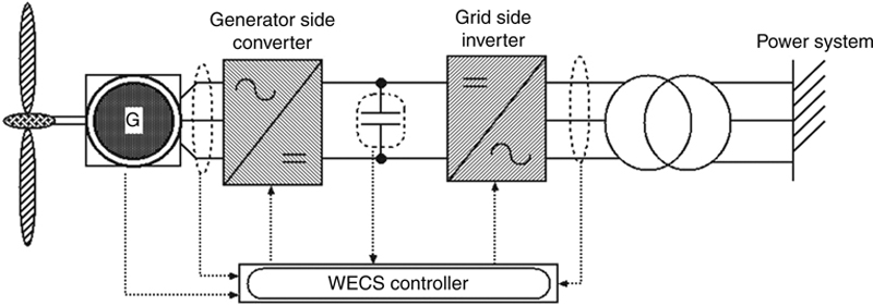
Figure 1.3 Wind energy conversion system.
Wind energy is an alternative to fossil fuels, it is plentiful, renewable, widely distributed, clean, low cost, produces no emissions during operation, and uses a tiny land area [14]. The effects on the environment are generally less problematic than those from other conventional power sources. Due to the variable wind speed, the output power of the WECS fluctuates and may create a frequency deviation of the power grid. To solve this problem, much research has already been conducted.
The world wind energy association (WWEA) published the key statistics of the World Wind Energy Report 2013.
The world wind energy capacity reached 318.5 GW by end of 2013 (this was 282.2 GW in 2012). In total, 103 countries are today using wind power on commercial basis. China was still by far the leading wind market with a new capacity of 16 GW and a total capacity of 91.3 GW. Wind power contributes close to 4% of the global electricity demand. For the year 2020, the WWEA predicts a wind capacity of more than 700 GW [15].
1.3.2. PV energy system
PV power systems convert sunlight directly into electricity. The PV system can be stand-alone (off-grid) or grid connected. Like WECS, PV is also a clean source of energy. However, the primary obstacle to increased use of PV systems is their high initial cost but continuous price reductions have been occurring. In some off-grid locations as short as one-quarter of a mile, PV systems can be cost-effective versus the costs of running power lines into the property and the subsequent continual electric charges. PV modules can be grouped together as an array of modules connected in series and parallel to provide any level of power requirements, from W to kW, and MW size. The PV energy generation system with battery pack is shown in Fig. 1.4. The PV array receives power from the sunlight and generates electricity, and a DC–DC converter converts the output voltage into a desired level. Depending on the PV system requirements, a battery energy storage system (BESS) stores the power into the battery and delivers the power to the PV system. A DC–AC inverter transports power to the power grid.

Figure 1.4 PV energy system.
1.3.3. Biomass
Biomass fuels generate energy from things that once lived such as wood products, dried vegetation, crop residues, aquatic plants, and even garbage. When plants lived, they used a lot of the sun’s energy to make their own food (photosynthesis). They stored the foods in the plants in a form of chemical energy. As the plants died, the energy became entrapped in the remains. This trapped energy is usually released by burning and can be converted into biomass energy. Wood remains the largest biomass energy source to date. Industrial biomass can be grown from numerous types of plants, including miscanthus, switchgrass, hemp, corn, poplar, willow, sorghum, sugarcane, bamboo, and a variety of tree species, ranging from eucalyptus to oil palm [16]. Burning materials like wood, waste, and other plant matters releases stored chemical energy in the form of heat, which can be used to turn shaft to produce electricity.
The use of biomass can be environmentally friendly because the biomass is reduced, recycled, and then reused. It is also a renewable resource because plants that can make biomass can be grown over and over. Biomass takes carbon out of the atmosphere while it is growing, and returns it as it is burned. If it is managed on a sustainable basis, biomass is harvested as part of a constantly replenished crop. This is either during woodland or arboricultural management or coppicing or as part of a continuous programmed of replanting with the new growth taking up CO2 from the atmosphere at the same time as it is released by combustion of the previous harvest. The energy stored in biomass fuels came originally from the sun.
Biomass is such a widely utilized source of energy, probably due to its low cost and indigenous nature, that it accounts for almost 6.9% of the world’s total energy supply.
1.3.4. Geothermal energy
Deep down in the Earth’s coating, molten rock exists, and it is simply rocks that have melted into liquid form as a result of excessive heat under the Earth. This can be found about 1800 miles deep below the surface, but closer to the surface, the rock layers are hot enough to keep water and air spaces there at a temperature of about 10–16°C. Geothermal technology takes advantage of the hot close-to-Earth-surface temperatures to generate power.
In places with hotter “close-to-Earth-surface” temperatures, deep wells can be drilled and cold water pumped down. The water runs through splinters in the rocks and is heated up. It comebacks to the surface as hot water and steam, where its energy can be used to drive turbines and generates electricity. Geothermal energy is also known as a renewable energy source because the water is refilled by the rainfall, and the heat is continuously produced by the Earth. Geothermal systems are extremely environmentally friendly, unlike conventional power stations. Even though it may occasionally release some gases from deep down inside the Earth, which may be slightly harmful, these can be contained quite easily. Again the cost of the land on which to build a geothermal power plant is usually less expensive than the construction of an oil, gas, coal, or nuclear power plant. Geothermal energy accounts for more than 6 GW of generated energy, and is installed in 21 countries across the world [17].
1.3.5. Hydro energy
Moving water generates kinetic energy. This can be transferred into useful energy in different ways. Hydroelectric power schemes store water high up in dams. Water has gravitational potential energy which is released when it falls. The moving water turns the generator shaft, producing electricity. Hydro energy is also a renewable energy and there is no possibility to generate emission. Hydro energy provides almost 2.7% of the world’s total energy supply.
1.4. Energy storage systems
Energy storage systems are an essential part of the renewable power generation system. The renewable power sources like solar, wind, and hydro are fluctuating resources. To supply a smooth output power to the power grid, energy storage systems are installed to the power generation system. Again the renewable sources (wind and solar) are unreliable, and in the case of the wind energy, the wind velocity sometimes drops below the power generation level, and sunlight may only be available 6–8 h per day to generate electricity. When the power generation becomes zero or the energy demand is high, the energy storage systems can deliver power to the consumers. Therefore, an energy storage system can be an important component of the SG system to improve the reliability of the power network. There are various types of energy storages, such as electric double layer capacitor (EDLC), BESS, superconducting magnetic energy storage (SMES), flywheel (FW), plug in electric vehicle (PEV), etc. A short description of these energy system storage systems is given in this section.
1.4.1. Electric double layer capacitor
EDLC is also known as super capacitor or ultra capacitor. The EDLC is an electrochemical capacitor employing conducting polymers as the electrodes [18,19]. The EDLC enables large power effects per weight having a goal up to 10 kW/kg but a storage capacity around 10 Wh/kg only. The storage time is short or typically up to 30–60 s. A 1-m3 EDLC to rage may, in the future, yield a 1–5 MW power pulse and weight 100–500 kg [20]. The price is around 200–600 €/kWh and 50–150 €/Wh but in 5–10 years a price level of 10–15 €/Wh is predicted. The most important drawback of EDLCs is their high cost [21].
1.4.2. Battery energy storage system
Batteries are a well-established technology for storage the electricity. The power and capacity that are bound together through the electrode surface means that increasing the power level simultaneously increases the storage capacity. Many types of batteries are now mature technologies. In fact, research activities involving lead–acid batteries have been conducted for over 140 years. Notwithstanding, a tremendous effort is being carried out to turn technologies like nickel–cadmium (Ni–Cd), sodium–sulfur (NaS), and lithium ion (Li ion) batteries into cost effective options for higher power applications. The capital power costs of the lead–acid, Ni–Cd, NaS, and Li ion may vary from 50–100, 400–2400, 210–250, and 900–1300 $/kWh, respectively [22,23].
1.4.3. Superconducting magnetic energy storage
The SMES system is a relatively recent technology. Its operation is based on storing energy in a magnetic field, which is created by a DC current through a large superconducting coil at a cryogenic temperature. The energy stored is calculated as the product of the self-inductance of the coil and the square of the current flowing through it. The response time is very short. The SMES technology has been demonstrated but the price is still very high. According to [24], the power injection of a 1 MW/1 kWh SMES can be increased by 200 kW only in 20 ms and the capital power cost may vary between 1,000 and 10,000 $/kW.
1.4.4. Flywheel
In an FW the storage capacity is based on the kinetic energy of a rotating disc which depends on the square of the rotational speed. A mass rotates on two magnetic bearings in order to decrease friction at high speed, coupled with an electric machine. Energy is transferred to the FW when the machine operates as a motor (the FW accelerates), charging the energy storage device. The FW energy storage system (FESS) is discharged when the electric machine regenerates through the drive (slowing the FW). FESSs have long lifetimes, high energy density, and a large maximum output power. The energy efficiency of an FESS can be as high as 90%. Typical capacities range from 3–133 kWh.
1.4.5. Plug in electric vehicle
Recent PEVs have been increased extensively and usually include a BESS. PEVs may play an important part in balancing the energy on the grid by serving as distributed sources of stored energy, a concept called “vehicle-to-grid”. By drawing on a large number of batteries plugged into the SG throughout its service region, a utility can potentially inject extra power into the grid during critical peak times, avoiding brownouts and rolling blackouts. Therefore, they can play a vital role to improve the power system reliability and the power quality of the SG. PEVs can drastically lessen the dependence on oil, and they emit nothing about air pollutants when running in all-electric modes. However, they do rely on power plants to charge their batteries, and conventional fossil-fueled power plants release pollution. To run a PEV as cleanly as possible, it needs to be charged in the hours of the morning when power demand is at its lowest and when wind power is typically at its peak. The SG technologies will help to meet this goal by interacting with the PEV to charge it at the most optimal time [25].
1.5. Smart grid
The electrical grid was built in the 1890s and improved upon as technology advanced through each decade. This type of the traditional grid includes centralized power generation, and at distribution level one-directional power flow and weak market integration [25].
The world’s electricity systems face a number of challenges, including ageing infrastructure, continued growth in demand, the integration of increasing numbers of variable renewable energy sources, electric vehicles and other distributed networks, the need to improve the security of supply, and the need to lower carbon emissions. To move forward, we need a new kind of electric grid, one that is built from the bottom up to handle the groundswell of digital and computerized equipment and technology dependent on it – and one that can automate and manage the increasing complexity and needs of electricity in the 21st century. SG technologies offer ways not just to meet these challenges but also to develop a cleaner energy supply that is more energy efficient, more affordable, and more sustainable. An SG is an electricity network that uses digital and other advanced technologies to monitor and manage the transport of electricity from all generation sources to meet the varying electricity demands of the user. SGs coordinate the needs and capabilities of all generators, grid operators, end-users, and electricity market stakeholders to operate all parts of the system as efficiently as possible, minimizing costs and environmental impacts while maximizing system reliability, resilience, and stability [26]. An SG includes centralized and distributed power generation produced substantially by renewable energy sources. It integrates distributed and active resources (ie, generation, demand, storage, and electricity vehicles) into energy markets and power systems. SGs can be characterized by a controllable multidirectional power flow. Following are the general features of a SG system [26]:
▪ Wide-area monitoring and control
▪ Information and communication technology integration
▪ Renewable and distributed generation integration
▪ Transmission enhancement
▪ Distribution grid management
▪ Advanced metering infrastructure
▪ Electric vehicle charging infrastructure
▪ Demand-side management systems
An emission-free SG system is shown in Fig. 1.5. The SG includes distributed renewable sources, PEV, energy demand, and control system. The integration of DG and flexible loads in a distribution network will benefit the network when managed appropriately. To lessen distribution losses, voltage regulation within the acceptable range, smooth power flow at the interconnection point, and stable power output to the power network are vital issues for the SG system, when DGs are integrated as power generation sources. The combination of DG and other active sources into a distribution system is needed in order to fully exploit the benefits of active resources in the network management. With proper management of active resources the overall system performance may be enhanced from presently used practices. One important control task in power systems is to maintain balance between power production and consumption which means keeping the power system’s frequency at a proper level. This procedure is becoming more and more challenging due to an increase in the penetration level of intermittent renewable power production. In recent years, there have also been many serious frequency unsteadiness related to wide-area power system blackouts in Europe and the USA, and their costs, both economical and social, are high [27].

Figure 1.5 Schematic diagram of the zero-emission smart grid integrated with the distributed renewable energy sources, intelligent power controller, PEV, energy storage, and energy demand.
..................Content has been hidden....................
You can't read the all page of ebook, please click here login for view all page.