Chapter 8

Lightning protections of renewable energy generation systems

Shozo Sekioka    Department of Electrical & Electronic Engineering, Shonan Institute of Technology, Japan

Abstract

The top of a blade of a wind turbine, with a couple of MW capacity, is more than 100 m high. In general, lightning tends to strike higher structures. Accordingly, lightning often strikes a wind tower or a blade. Most lightning currents have high amplitude and high frequency, and sometimes have large energy. The current generates a high voltage in the power apparatus and measurement and control systems in the wind turbine generation system, and causes damage to the apparatus, causing the system to malfunction. Distributed energy resources outside a house or building have a risk of lightning damage.

Keywords

lightning
lightning protection
lightning damage
lightning surge
winter lightning

8.1. Introduction

The top of a blade of a wind turbine, with a couple of MW capacity, is more than 100 m high. In general, lightning tends to strike higher structures [1]. Accordingly, lightning often strikes a wind tower or a blade. Most lightning currents have high amplitude and high frequency, and sometimes have large energy. The current generates a high voltage in the power apparatus and measurement and control systems in the wind turbine generation system, and causes damage to the apparatus, causing the system to malfunction. Distributed energy resources outside a house or building have a risk of lightning damage.
Lightning surges come into a wind turbine generation system consisting of single wind turbine and an overhead line as illustrated in Fig. 8.1. Lightning surges comes from an overhead line such as a distribution/transmission line or a telecommunication line, direct lightning strikes a wind tower or a blade, and ground potential rise caused by lightning hit to the ground or the tower.
image
Figure 8.1 Lightning events in a wind turbine generation system.
The mechanisms that cause lightning damage are classified as follows.
1. Lightning overvoltage: high current with high frequency generates high voltage and causes breakdown.
2. Energy: lightning current with long duration has large energy and causes meltdown or burnout of conductors and a blade.
3. Lightning electromagnetic impulse: lightning current with high frequency generates impulse voltages. The impulse voltage on an overhead line caused by a nearby lightning is called lightning-induced voltage. The crest voltage and energy of the lightning-induced voltage are relatively low. Thus, the lightning-induced voltage is not main cause of serious lightning damage. The lightning electromagnetic impulses frequently appear in various networks, and sometimes cause malfunctions. The insulation level of a power distribution line is relatively low. Therefore, power distribution lines have been targeted for the lightning-induced voltage in lightning protection design [2]. The use of surge arrester (Ar) is effective for the protection of the distribution lines against the lightning-induced voltages, and lightning outages have been decreased. Thus, the lightning protection for distribution lines mainly considers a direct lightning hit to the line [3].
Wind turbine blades sometimes explode and scatter due to the lightning flash. Serious damage to a wind turbine blade causes serious economic losses due to long-term loss of service and its cost to repair the blade [4]. Abnormal lightning such as winter lightning, which is frequently observed along the coast of the Sea of Japan [58], causes serious damage to wind power generation [4,9]. Many utilities in Japan gave up maintaining wind power generation because some lightning damage in winter seasons needed long time and much money to repair the blade during the winter. Therefore, the rational lightning protection design for wind turbine is very important to stable generation.
Home photovoltaic panels are set on the roof of a house or top of a building. Considering lightning sometimes strikes an antenna on a roof, lightning might strike a photovoltaic panel on a roof. Air termination systems such as a lightning rod or a shielding wire are used to prevent photovoltaic panels from damage caused by direct lightning flashes. The insulation level of photovoltaic system is very low in comparison with that of distribution line. Therefore, the lightning protection design for photovoltaic system is targeted for lightning-induced voltages [10,11]. However, lightning flashes with low lightning current might strike a photovoltaic panel on a roof of a house based on an electrogeometric model (EGM) [12] even if an antenna stands besides the panel. Direct lightning flash causes serious damage to photovoltaic systems. If low lightning current cause no damage in the system, direct lightning hit should be considered in lightning protection design of photovoltaic system. Photovoltaic generation needs large area to generate MW of electric power. The height of the system is low, but the probability of the lightning striking a photovoltaic panel is not small.
Wind turbine and photovoltaic systems related to the lightning protection should be designed on the basis of the IEC international standards 62305 series [1316] and 61400-24 [17]. Lightning current parameters exceeding the values used in the IEC standards are sometimes observed. Thus, lightning phenomena are not well known. Moreover utilities want to make the cost for lightning protection as low as possible. Therefore, it is very important to know lightning protection methods for distributed energy resources, and to improve them. This chapter describes the lightning protection methods of wind turbine and photovoltaic systems, which are frequently damaged by lightning.

8.2. Lightning protection principle

The lightning protection of electrical equipments and signal transmission systems should be carried out using the following methods.
1. Shielding: air termination system such as a shielding wire or a lightning rod catches a lightning discharge. Overhead lines, buildings, and structures can be protected from a direct lightning strike using the air termination system.
2. Reduction: lightning overvoltage becomes lower by reducing impedance. Equipotential bonding method is a kind of reduction method because this bonding reduces voltage differences in grounding system.
3. Suppression: surge arrester and surge protective device (SPD) suppress lightning overvoltage.
Fig. 8.2 illustrates the reduction and suppression against lightning overvoltage.
image
Figure 8.2 Reduction and suppression for lightning overvoltage.

8.2.1. Reduction

The reduction method makes lightning overvoltages lower by reducing impedances. The overvoltage is proportional to impedance. Therefore, breakdown occurrences are decreased by the reduction of the overvoltage. However, if lightning current is much high, the voltage in a system exceeds the breakdown voltage, and lightning damage occur. The reduction of grounding resistance is a typical reduction method. The reduction of the grounding resistance at a lightning striking point is very effective. The grounding resistance is approximately inversely proportional to the surface area of a grounding electrode. A large grounding electrode must be driven in the ground to obtain low grounding resistance. Terminal voltage V (V) is approximately given by

V=Ldidt+Ri

image(8.1)
where L is the inductance of the down conductor (μH), R is the grounding resistance (Ω), and i is the injected current into the grounding electrode (A). L is approximately 1 μH/m.
Even if the grounding resistance is very low, high inductance of the down conductor raises the terminal voltage for high frequency current. Thus, the down conductor should be as short as possible.

8.2.2. Suppression

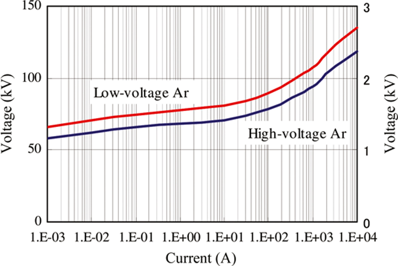
Zinc oxide varistor has an excellent nonlinear characteristic. Fig. 8.3 shows an example of voltage–current characteristics of an SPD using the ZnO element. The horizontal axis in Fig. 8.3 is logarithmic scale. Therefore, the SPD or Ar terminal voltage is almost constant for the variation of the injected current. The Ar and SPD are modeled by a cell in convenience. Thus, the terminal voltage with an Ar or SPD is suppressed under the value, and equipments can be protected from lightning overvoltages. The voltage is effectively suppressed at which an Ar or SPD is installed. The Ar or SPD cannot cover all the system, and many Ars or SPDs must be installed in the system. Fig. 8.4a illustrates a calculation circuit including an SPD and a device. Devices are often represented by capacitance in lightning surge analysis. The voltage of the SPD is constant Ea, the line characteristics are the surge impedance Z0 of 500 Ω, the surge velocity v0 of 300 m/μs, which is equal to the speed of light. Forward traveling voltage e = at for t < Tf, where Tf is the rise time of the forward traveling voltage, propagates on a line from far end of the line, which is semi-infinite length of line. The line is terminated at the end of the line through a capacitance C, which represents a device. An SPD is connected to the line at the distance x from the capacitance. Fig. 8.4b shows simulation results of the terminal voltage V in cases of x = 10 m and 50 m. aTf in the simulation is 2Ea, and Tf = 1 μs. The electromagnetic transients program is used. The capacitance of the device is an important factor. The higher the capacitance, the terminal voltage becomes higher [18]. The amplitude of resonance voltage is dependent on the distance from the SPD. This phenomenon can be explained by the oscillation of a circuit consisting of line inductance and device capacitance [19]. The SPD/Ar must be installed as close as to the device to be protected.
image
Figure 8.3 V–I characteristic of SPD.
image
Figure 8.4 Influence of distance between an SPD and a device on device voltage.
(a) Simulation circuit for an SPD and an apparatus. (b) Lightning overvoltage at line end.
The grounding method affects the effectiveness of SPD on the lightning protection level. The circuit for discussion consists of an impulse voltage generator, an SPD including a series gap, and a device for testing. Experimental results are shown in Fig. 8.5 [20]. Upper curve in the measurement results are applied currents. The following three cases are discussed on the influence of grounding system on overvoltage on a device.
1. Down conductor of the device is connected to the SPD, and is grounded at the SPD.
SPD terminal voltage, V1, and device terminal voltage, V2, are effectively suppressed by the SPD, and these voltages become almost same.
2. Down conductor of the device is connected to the SPD, and is grounded at the instrument.
V2 is much higher than V1. This difference is caused by the inductance voltage in the down conductor of the SPD due to the SPD discharge current; V = L × di/dt.
3. Grounding of the SPD is isolated from that of the device.
V2 is much higher than V1. The voltage difference in this case is higher than that in case (b). Thus, an SPD and a device to be protected should be commonly grounded at the SPD.
The equipotential bonding method is useful technique as is clear from the experimental results. The grounding system related to down conductors must be carefully selected to suppress lightning overvoltages using SPDs effectively.
image
Figure 8.5 Experimental study of SPD grounding methods [20].
(a) Down conductor of the instrument is connected to the SPD, and is grounded at the SPD. (b) Down conductor of the instrument is connected to the SPD, and is grounded at the instrument. (c) Grounding of the SPD is isolated from that of the instrument.

8.2.3. Shielding

For simplicity, the EGM proposed by Armstrong and Whitehead [12], which is used in lightning protection design of electric power system, is adopted in this chapter. Fig. 8.6 illustrates an example of the application of the EGM to a transmission line. The lightning striking distance, rc (m), is dependent on the crest value of lightning current, and is given by:

rc=kImα

image(8.2)
where Im is the crest value of lightning current (kA). k and α are empirically determined based on experimental or observation results, and many values are proposed [1].
image
Figure 8.6 Electrogeometric model.
Lightning flashes with higher currents generate longer lightning striking distance, and a shielding wire catches the lightning strike. There are three conductors: a shielding wire, a phase conductor, and the ground. Lightning strikes LS1f with low current goes down outside of the exposure arc SB, and reaches the exposure arc PB. This means the lightning strikes the power conductor, namely shielding failure. In case of higher lightning current, the exposure arc SA catches the lightning strike LS1s, and the shielding wire succeeds in shielding. Thus, lower currents tend to cause shielding failure. When lightning strikes are located outside an exposure arc of the power conductor, the lightning hits the ground (LS2s). Line and structures can be prevented from direct lightning hit by properly arranging the air-termination system such as shielding wires or lightning rods.

8.2.4. Lightning characteristics for lightning protection design

Applied voltage waveform for lightning impulse withstand voltage test is a double exponential function k(eαt − eβt). A typical lightning current waveform is shown in Fig. 8.7 [21]. Most lightning currents show the negative polarity. Two time scales, A and B, in Fig. 8.8 are the average current waveforms for negative first and subsequent strikes, respectively. The waveform is normalized by the crest value. The lightning current waveforms are similar to the test voltage waveform. Most of lightning currents have high amplitude, but wave duration is less than 1 ms. This type of lightning current mainly causes breakdown or electromagnetic interference.
image
Figure 8.7 Average negative first and subsequent stroke waveform [21].
image
Figure 8.8 Cumulative statistical distributions of peak values of directly observed lightning currents (solid lines) and their log-normal approximations (dashed lines).
(1) Negative first strokes, (2) negative subsequent strokes, and (3) positive first strokes [21]
The Heidler function as a lightning current waveform model is frequently used in lightning surge analysis [22]. This model is given by:

I(t)=I0η(t/τ1)n(t/τ1)n+1exp(t/τ2)

image(8.3)
A triangle wave shape is also often used in lightning protection design and surge analysis because this model is very simple and convenient [23].
Fig. 8.8 shows the cumulative statistical distributions (solid line curves) of return-strike peak currents for (1) negative first strikes, (2) negative subsequent strikes, and (3) positive strikes (each was the only strike in a flash) [21,24]. Subsequent return strikes are characterized by 3–4 times higher current maximum steepness (current maximum rate of rise).
The winter lightning current shows a variety of and complex waveforms such as long-duration waveform plus many pulses and having both polarities. The average peak value of the winter lightning current is approximately equal to that of the summer lightning. The winter lightning current has much longer wave tail duration. Consequently, the winter lightning sometimes shows large electric charge. This is equivalent to large energy, and causes serious damage in wind turbines. Fig. 8.9a illustrates a wind power station in Japan, and Fig. 8.9b shows an observation result of lightning current injected into the lightning tower in the power station [25]. The peak value of the lightning current is estimated to be about 240 kA. This value much exceeds that used in the IEC standard. The lightning current shown in Fig. 8.9b is one of giant lightning flashes. The current waveform is quite different from the summer lightning. Observation results of the lightning currents in the wind turbines suggest the following remarks [26]:
Some of the winter lightning currents have shown a time duration of more than 200 ms.
Some of the winter lightning currents with the electric charge of more than 300 C, which is the protection level recommended by the IEC international standard, have been observed, and the maximum value is approximately 1270 C.
image
Figure 8.9 Observation of lightning current in a wind power station [25].
(a) Observation point at Nadachi Wind Power Station. (b) Observation result of lightning current.
Thus, the IEC international standard is not sufficient for the Japanese wind turbine generation systems against the winter lightning in Japan.
The stepped leader of summer lightning develops from a cloud to the ground, and the return strike with high current starts from the ground, a structure or a tree to the cloud. A downward lightning is observed in summer as shown in Fig. 8.10a. On the other hand, the winter lightning frequently has an upward lightning strike as in Fig. 8.10b [27]. The difference of lightning strikes affects the lightning striking point and shielding failure.
image
Figure 8.10 Example of lightning strokes in summer and winter in Japan [27].
(a) Summer lightning. (b) Winter lightning.
The other parameters related to the lightning such as ground flash density, lightning channel impedance, and return strike velocity should be known. Updated data on the lightning parameters for engineering including theses characteristics are available [28] (Table 8.1).

Table 8.1

Parameters of Downward Negative Lightning [24]

Parameters Units Sample Size Exceeding Tabulated Value (%)
95% 50% 5%

Peak current (minimum 2 kA)

    First strokes

    Subsequent strokes

kA

101

135

14

4.6

30

12

80

30

Charge (total charge)

    First strokes

    Subsequent strokes

    Complete flash

C

93

122

94

1.1

0.2

1.3

5.2

1.4

7.5

24

11

40

Impulse charge (excluding continuing current)

    First strokes

    Subsequent strokes

C

90

117

1.1

0.22

4.5

0.95

20

4

Front duration (2 kA to peak)

    First strokes

    Subsequent strokes

μs

89

118

1.8

0.22

5.5

1.1

18

4.5

Maximum di/dt

    First strokes

    Subsequent strokes

kA/μs

92

122

5.5

12

12

40

32

120

Stroke duration (2 kA to half peak value on the tail)

    First strokes

    Subsequent strokes

μs

90

115

30

6.5

75

32

200

140

Action integral (∫i2dt)

    First strokes

    Subsequent strokes

A2s

91

88

6.0 x 10³

5.5 x 10²

5.5 x 10⁴

6.0 x 10³

5.5 x 10⁵

5.2 x 10⁴

Time interval between strokes ms 133 7 33 150

Flash duration

    All flashes

    Excluding single-stroke flashes

ms

94

39

0.15

31

13

180

1100

900

where I0, η, τ1, n, and τ2 are constants, and are empirically determined.

8.2.5. IEC international standard [1317]

The lightning protection zone (LPZ) as shown in Fig. 8.11 and Table 8.2 was introduced in the IEC 62305 for lightning protection design. Protection measures such as the lightning protection system (LPS), shielding wires, magnetic shields, and SPD determine the LPZs. IEC 62305 also introduces four lightning protection levels (LPL) I–IV. For each LPL, a set of maximum and minimum lightning current parameters is fixed. The maximum values of lightning current parameters for the different LPLs are given in Table 8.3 [13], and are used to design lightning protection components. The minimum amplitudes of lightning current for the different LPLs are used to determine the rolling sphere radius to define the LPZ 0B, which cannot be reached by direct lightning strike. The minimum values of lightning current parameters together with the related rolling sphere radius are given in Table 8.4 [13]. The rolling sphere model [29] is applied to a wind turbine. This model is an EGM. The lightning striking distance in the IEC 62305 is dependent on the LPL. They are used for positioning of the air-termination system and to define the LPZ 0B.
image
Figure 8.11 Division of wind turbine into different lightning protection zones [17].

Table 8.2

Definition of Lightning Protection Zones

Outer Zones

LPZ 0 Zone where the threat is due to the unattenuated lightning electromagnetic field and where the internal systems may be subjected to full or partial lightning surge current.
LPZ 0A Zone where the threat is due to the direct lightning flash and the full lightning electromagnetic field. The internal systems may be subjected to full or partial lightning surge current.
LPZ 0B Zone protected against direct lightning flashes but where the threat is the full lightning electromagnetic field. The internal systems may be subjected to partial lightning surge currents.

Inner Zones

LPZ 1 Zone where the surge current is limited by current sharing and by SPDs at the boundary. Spatial shielding may attenuate the lightning electromagnetic field.
LPZ 2,...n Zone where the surge current may be further limited by current sharing and by additional SPDs at the boundary. Additional spatial shielding may be used to further attenuate the lightning electromagnetic field.

Table 8.3

Maximum Values of Lightning Parameters According to LPL

First Short Positive Stroke LPL
Current Parameters Symbol Unit I II III IV
Peak current I kA 200 150 100
Short stroke charge Q short C 100 75 50
Specific energy W/R MJ/Ω 10 5,6 2,5
Time parameters T 1/T 2 μs/μs 10/350
First Short Negative Strokea LPL
Peak current I kA 100 75 50
Average steepness di/dt kA/μs 100 75 50
Time parameters T 1/T 2 μs/μs 1/200
Subsequent Short Strokea LPL
Current Parameters Symbol Unit I II III IV
Peak current I kA 50 37,5 25
Average steepness di/dt kA/μs 200 150 100
Time parameters T 1/T 2 μs/μs 0,25/100
Long Stroke LPL
Current Parameters Symbol Unit I II III IV
Long stroke charge Q long C 200 150 100
Time parameter T long s 0,5
Flash LPL
Current Parameters Symbol Unit I II III IV
Flash charge Q flash C 300 225 150

a  The use of this wave shape concerns only calculations and not testing.

Table 8.4

Minimum Values of Lightning Parameters and Related Rolling Sphere Radius Corresponding to LPL

Interception Criteria LPL
Symbol Unit I II III IV
Minimum peak current I kA 3 5 10 16
Rolling sphere radius r m 20 30 45 60

The nacelle, the tower, and the transformer kiosk are protection zone LPZ 1. The devices inside metal cabinets in LPZ 1 are in protection zone LPZ 2. For instance, control systems inside a cabinet or a metal tower are in LPZ 2, but in a metal cabinet outside the tower they are in LPZ 1 or LPZ 2. Very sensitive equipment may be placed within a still more protected zone LPZ 3. The division of the wind turbine into LPZs is a tool to ensure systematic and sufficient protection of all components of the wind turbine. For instance, protection against overvoltages is only necessary for cables passing from one zone into another zone with more sensitive components, whereas internal connections within the zone may be unprotected. Basic protection measures in an LPMS according to IEC 62305-4 include bonding, magnetic and electrical shielding of cables, line routing (system installation), coordinated SPD protection, and grounding.
When the structure is protected by an LPS, a Type 1 SPD needs to be provided at the line entrance to provide equipotential bonding between the line and the grounding system. When there is no LPS, the SPD at the entrance is still needed to provide a border between an LPZ 1 inside the structure and an LPZ 0 outside the structure.

8.3. Lightning protection for wind power generation systems

8.3.1. Lightning damage in wind power generation system

The main reason for outage for long periods is damage to blades. Some types of damage of blades are found in [4]. An example of the damage is shown in Fig. 8.12 [4].
image
Figure 8.12 A case of lightning damage in a wind turbine (same turbine and same event) [4].
(a) Blade burnout; (b) blade burnout and wire melting.
Fig. 8.13 shows outage period of blades and control equipments due to lightning as a parameter of season [9]. This period reflects an influence of the damage on power supply. The number of the damaged control equipments is larger than that of the blades. However, damage of a blade caused by winter lightning stops generation for long periods. Thus, the damage of the blades is the most serious problem for wind power generation. It is hard to repair the damaged blades in winter due to the strong snow and wind. Damage to control systems are mainly observed. This is caused by malfunctions due to the lightning electromagnetic impulse.
image
Figure 8.13 Damage of wind turbine caused by lightning.
Observed lightning currents often have high amplitude or large electric charge. However, the large lightning flash does not always cause damage [26]. A rational lightning protection design by properly arranging SPDs and constructing air-termination system is required.

8.3.2. Lightning protection methods for wind turbine

Fig. 8.14 gives an example of lightning protection measures for a wind turbine generation system [17]. SPDs must be installed at entrances of wind tower to a service line and a telecommunication line. Wind tower and nacelle themselves are regarded to be Faraday cages. Equipments and instruments in the tower and the nacelle can be protected from lightning overvoltages by the equipotential bonding and the installation of the SPDs.
image
Figure 8.14 An example of lightning protection management system considering LPZs [17].
Fig. 8.14 is an example of how to document LPMS division of electrical system into protection zones with indication of where circuits cross LPZ boundaries and showing the long cables between tower foundation and nacelle [17]. It is the best method to install a number of SPDs at every entrances of equipment and boundary of the LPZs. A cable with metallic sheath reduces an influence of external electromagnetic fields by grounding the metallic sheath. The core conductor is located very close to the metallic sheath, and the voltage between the core conductor and the metallic sheath is low because of the coupling factor. Considering the nacelle and the wind tower are a kind of Faraday cage, and grounding the metallic sheath and the installation of SPDs properly on the basis of the equipotential bonding, the voltages on the equipment in the nacelle and the tower can be less than the lightning impulse withstand voltage.

8.3.3. Grounding resistance

Lightning performance of a grounding system must be considered for rational lightning protection design [30]. Transient response of grounding resistance is simply represented by circuits shown in Fig. 8.15. High grounding resistance of more than 100 Ω often shows a capacitive type and a low resistance of less than 10 Ω the inductive type. Thus, the grounding resistance should be treated as impedance. The steady state grounding resistance for a wind turbine is designed to be as low as possible. The grounding resistance of wind turbines is designed to be less than 2–10 Ω. The grounding resistance is lower as the grounding electrode is larger. Therefore, high cost is required to obtain very low grounding resistance in high resistivity soil.
image
Figure 8.15 Grounding resistance for lightning current.
(a) Equivalent circuits of grounding resistance. (b) Transient response of grounding resistance.
The ground potential rise of a grounding system of an actual wind turbine was measured. The measurement results are verified using the finite-difference time-domain (FDTD) method [31]. Fig. 8.16a illustrates the grounding system consisting of a foundation, which is constructed with reinforced concrete, a grounding mesh and foundation feet. Measurement result of the ground potential rise of the grounding system is shown in Fig. 8.16b [32]. The applied current has stepwise waveform, and the voltage is regarded to be transient grounding resistance. The transient grounding resistance is the inductive type. The maximum value is much higher than the steady state grounding resistance. Thus, the transient response of grounding resistance is very important for estimating lightning overvoltages in wind turbine generation system. Simulation results using the FDTD method agree well with the experimental results. Thus, the FDTD method is a useful tool to predict transient response of wind turbine grounding system. Mesh type grounding electrode, which is frequently used in substations, also shows the same variation [33].
image
Figure 8.16 Measurement results of the grounding system compared with FDTD calculated results [32].
(a) Configuration and dimension of grounding system of an actual wind turbine generator system. (b) Comparison of measured results of ground potential rise with simulation results using FDTD.
A tower foundation can be regarded to be a large grounding electrode, and is an excellent grounding electrode, and very low grounding resistance can be obtained by the tower foundation alone. However, it is difficult to obtain low grounding resistance, when the wind tower is constructed in high-soil-resistivity yard. Auxiliary grounding electrodes such as horizontal and vertical grounding conductors, and a ring electrode are often used to obtain the low steady–state grounding resistance. The grounding electrodes of the towers in the wind farm are sometimes connected each other using the long grounding conductors to obtain low steady–state grounding resistance [34].
For simplicity, the grounding resistance Rp of two grounding electrodes of a tower foundation and an auxiliary grounding electrode is given by:

Rp=R1R2Rm2R1+R22Rm

image(8.4)
where R1 and R2 are self-grounding resistances of a tower foundation and an auxiliary grounding electrode respectively, and Rm is the mutual grounding resistance.
The following two cases must be carefully considered in the grounding system design:
1. R1 ≈ Rm, a ring type grounding electrode is sometimes set near and around a tower foundation. If these electrodes are closed, Rm is almost equal to R1. As a result, the total grounding resistance is approximately equal to the tower footing resistance, namely Rp ≈ R1. In this case, the ring type electrode is not expected to reduce the grounding resistance. The ring type electrode has an important role to reduce foot voltage around the tower.
2. R1 <<R2, in case the grounding resistance of an auxiliary grounding electrode is sufficiently higher compared with R1, the total grounding resistance is approximately equal to the tower footing resistance. Thus, the reduction effect of the auxiliary grounding electrodes is not expected in this case.
Thus, a tower foundation is very useful grounding electrode, and auxiliary grounding electrodes are carefully selected so that mutual and self-grounding resistances are as low as possible. Simulation tools based on electromagnetic theory such as the FDTD method and the method of moment are useful for designing the grounding system.
Considering the reduction of the grounding resistance for lightning currents due to the soil ionization is small in case of low grounding resistance [33], the soil ionization effect on the grounding resistance of a wind turbine is not expected.
A down conductor for equipments in a nacelle is sometimes set along a wind tower. Breakdown and short circuit occurs between the down conductor and the tower due to lightning overvoltages [35]. Radius of a wind tower is very large, and the tower has low surge impedance. Therefore, the wind tower should be treated as a down conductor.

8.3.4. Lightning protection of blade using receptor [4,17]

Wind turbine blades are large and long hollow structures manufactured of composite materials such as glass fiber reinforced plastic, wood, wood laminate, and carbon fiber reinforced plastic. Wind turbine blades should be considered for lightning protection design as follows:
1. Height of a blade is very tall, and lightning frequently hits the blade.
2. Shielding wire, which is used in electric power systems, is not fundamentally adopted considering wind condition. Thus, shielding effects by the shielding wire are not expected.
3. Blade materials, such as FRP, are easy to burn.
4. Most of blades are composed of two pieces of shells and are hollow. Lightning discharges can intrude into the cavity resulting in a rupture of a blade.
Receptors are installed on a blade surface for lightning protection so that the damage of blade rupture or surface tearing can be reduced more effectively. A down conductor is installed inside the cavity of the blade, and leads the lightning current safely to the root end of the blade and onward to the earthed structure of the wind turbine. Serious blade damage can be mitigated by the receptor. A metal cap receptor on the tip edge of each blade is an improved type of the receptor. The receptors should be installed close to the tip part of a blade. The down conductor should be a thick wire for lightning current with large energy.

8.3.5. Energy coordination of surge arrester/surge protective device [36]

Winter lightning and continuing current sometimes have large energy enough to burn Ars and SPDs. When air-termination system works well, the most of lightning current is injected in to the ground. The ground potential rise due to the lightning current is the main reason to cause the large energy into the Ars and SPDs. A relation between current I(t) and electric charge Q(t) is given by:

Q(t)=0tI(T)dT

image(8.5)
Assuming impedance, Z, is constant, energy En(t) is given by:

En(t)=0tZ{I(T)}2dT=Z0t{I(T)}2dT

image(8.6)
∫{I(t)}2 corresponds to the action integral in Table 8.1. It is difficult to estimate Z and most of impedances are not constant. The electric charge is useful to estimate an influence of lightning current on a lightning damage. As is shown in Fig. 8.3, Ar and SPD voltages can be regarded to be constant, and the Ar and the SPD are modeled by the direct current (DC) voltage source, E0. The energy is given by:

En(t)=0tE0I(T)dT=E00tI(T)dT=E0Q(t)

image(8.7)
and is estimated from the electric charge.
Fig. 8.17 illustrates routes of lightning currents when the lightning strikes a receptor. In case of a wind farm, the distribution line can be replaced by neighboring towers.
image
Figure 8.17 Routes of lightning currents in case of lightning hit to a receptor.
The lightning current injected into the tower from the receptor (arrow 1) is flown into the ground through grounding electrodes (arrow 2). The current into the ground raises the ground potential rise. When the ground potential rise is higher than the surge arrester operation voltage, the transformer arrester acts, and a part of the injected current into the ground goes through the surge arresters (arrow 3). The lightning surge on a power cable in the tower transfers through the transformer (arrow 4). However, this surge is low, and can be ignored. A pert of the lightning current is flown into the ground through distribution line arresters (arrow 5).
Fig. 8.18 shows an equivalent circuit for direct lightning hit to a receptor. Current into the service line ID and the service line voltage VD are given by:

ID=RWIL(EW+ED)RD+RW

image(8.7)

VD=RDRWRD+RWILRDEWRWEDRD+RW

image(8.8)
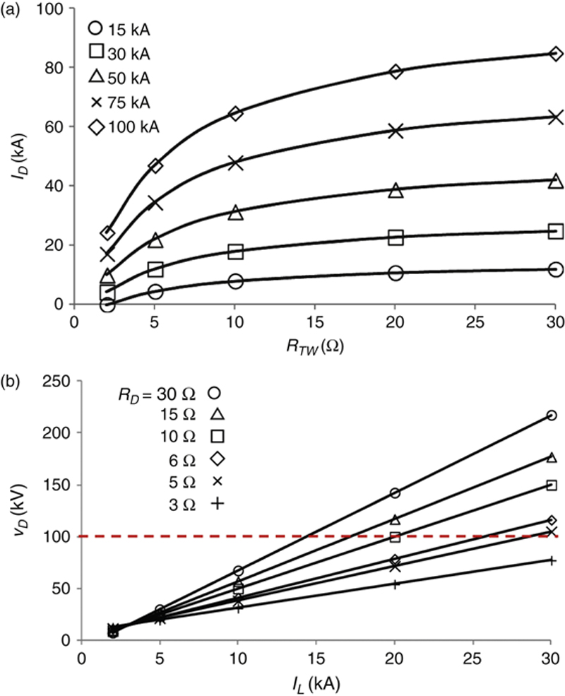
Calculated results using the equations are shown in Fig. 8.19, where ED = EW = 15 kV, and dotted line is flashover voltage of the service line. The grounding resistance of the wind turbine should be as low as possible because most of the lightning current is injected into the ground. The line voltage becomes high in comparison with line flashover voltage even if Ars are installed, because the ground potential rise becomes high. Thus, Ar capability is carefully selected, and wind turbines and lines must be coordinated on the insulation and energy.
image
Figure 8.18 Equivalent circuit for current distribution in case of lightning hit to a receptor.
image
Figure 8.19 Service line voltage and current.
(a) Service line current (RD = 15 Ω); (b) Service line voltage (RW = 10 Ω).

8.4. Lightning protection of wind farms

One of the countermeasures to protect wind turbine blades from the lightning is constructing lightning towers besides the wind turbine towers as shown in Fig. 8.20.
image
Figure 8.20 Shielding by lightning tower. (Source: Photo is taken by Uchinada-cho.)
The receptor is an air-termination system for blades. However, the receptor is small, and does not always catch the lightning. The lightning tower is a kind of independent giant lightning rod. When the lightning towers are constructed in a wind farm, those cover some wind towers against the lightning. The lightning tower needs to be as high as possible. However, the dimension and location of the lightning tower is restricted because the lightning tower affects the flow of wind.
There are 15 wind turbines in Nikaho wind park, which is located in Akita prefecture of Japan and facing the coast of the Sea of Japan. Observation of lightning discharges using still cameras got 99 lightning hits to wind turbines. An uneven distribution of the number of lightning hits on the wind turbines is shown in Fig. 8.21. The wind turbines, which are located at the end of a wind turbine line or facing the coast, are more often hit by lightning. Thus, the lightning discharge in a wind farm is dependent on the location of wind towers. This observation result suggests that if a lightning tower is constructed at the location to which the lightning most frequently hits, most lightning flashes can be caught by the lightning tower.
image
Figure 8.21 Lightning discharge observation at Nikaho wind park [4].
WTG, Wind turbine generator.
Lightning striking position is dependent on the dimension and location of structures, lightning striking angle and lightning peak current. The EGM is applied to the determination of the lightning striking point as illustrated in Fig. 8.22 [37]. It should be mainly considered to be spherical in the case of wind turbines. According to Fig. 8.22, the exposed surface changes due to not only the lightning current but also the direction and orientation of the blades. Fig. 8.23 shows a comparison of the calculated results using the EGM with the observation results. The comparison of the expected rate of lightning strikes seems to be reasonably good.
image
Figure 8.22 Exposed surface with a lightning tower and wind turbines [37].
image
Figure 8.23 Comparison of calculated results using the EGM with observation results for a wind tower and a lightning tower [37].
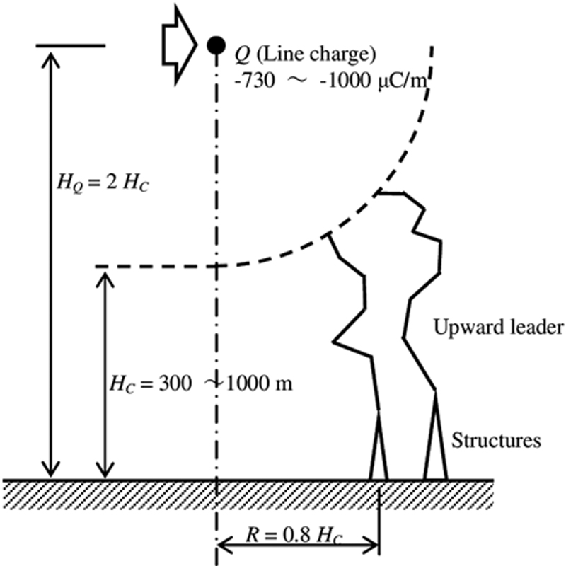
Winter lightning observed along the coast of the Sea of Japan, where many wind turbine generators are built, shows upward lightning discharge. The upward leader progression (ULP) model has been proposed to predict lightning protective effect of upward lighting [38]. The EGM was developed on the basis of the downward lightning developing from a cloud to the ground, and is hard to evaluate lightning shielding failure against winter lightning, namely upward lightning. The ULP model is applicable to winter lightning and a shielding effect of a lightning tower [39]. Fig. 8.24 illustrates configuration of cloud, a lightning tower, and wind turbine towers. The relationship between the direction of the cloud movement and location and height of the towers is very important. The estimated ratio of lightning strike to wind turbines using the ULP model is satisfactorily agrees with that of observation result [40] (Fig. 8.25).
image
Figure 8.24 Charge configuration used in the ULP model [41].
image
Figure 8.25 Comparison of calculated results using the ULP model with observation results for a wind tower and a lightning tower [40].
(a) Nikaho wind park. (b) Taikoyama wind park.

8.5. Lightning protection for photovoltaic power generation systems

The height of photovoltaic systems is low, and the probability of direct lightning hit to the photovoltaic system is low. Moreover, the withstand voltage of the photovoltaic system is much lower compared with the other electric power systems. Therefore, the lightning protection design for photovoltaic system concerns the air-termination system and lightning electromagnetic impulse such as lightning-induced voltage. Lightning protection for photovoltaic system is fundamentally based on the IEC standard.

8.5.1. Lightning damage in photovoltaic system

Only a few lightning damage in photovoltaic array has been reported. Most of lightning damage in actual photovoltaic systems occur in power conditioner and measurement and indicator equipment [41]. Fig. 8.26 illustrates an example of lightning protection measures for a photovoltaic system. Megasolar system frequently adopts lightning rods [42].
image
Figure 8.26 Possible installation of SPDs in case of a building with external LPS when separation distance is not kept [42].

8.5.2. Lightning protection against lightning overvoltages in photovoltaic systems

SPDs must be properly selected and installed according to the LPZ. The distance between the LPS and the metal structure of the photovoltaic array should be kept as short as possible to prevent the photovoltaic array from lightning damage. Insulation level of photovoltaic modules is basically determined by reverse withstand voltage of backward diodes.
LEMP generates high voltage but small energy. However, photovoltaic array continues generating DC voltage, and large energy is flown into SPDs. Therefore, a disconnector for an SPD in the DC side must be provided to disconnect the failed SPD from a line in case the failed SPD has been damaged due to high lightning surge exceeding its capability.

8.5.3. Direct lightning flash to photovoltaic system

Lightning strike with low current might strike a photovoltaic array based on EGM. An experiment of discharge to a photovoltaic array using an impulse voltage generator was carried out. Lightning impulse voltage with 1.2/50 μs is applied to a rod using the impulse voltage generator. Specification of a photovoltaic array is 70 W and 11.9 V. The thickness of the cover glass (tough glass) on photovoltaic cells is 2.5 mm, and the breakdown voltage of the glass is approximately 210 kV. The metal frame of the array is grounded in the experiments, but is not directly connected to the cells. Fig. 8.27 illustrates a photovoltaic array. The cell is polycrystalline silicon type.
image
Figure 8.27 Configuration of a photovoltaic array.
The 50% sparkover voltage of the rod-plate gap is almost equal to that of the rod array gap. Thus, the photovoltaic cells act a metal plate for lightning impulse voltages. Fig. 8.28 show an example of discharges in case of 0.3 m gap including sparkover and surface discharge [43]. The sparkover is attached to a point on the glass of the array under the rod, and then the surface discharge towards a frame, which is grounded, occurs. Generally speaking, surface discharge occurs on an insulated material above a conductor. Thus, photovoltaic cells can be regarded as a metallic plate for lightning impulse voltages. The experimental results suggest that a direct lightning strike with small lightning current to a photovoltaic array might not cause serious damage due to surface discharge on the glass. Therefore, it is possible to protect photovoltaic systems from direct lightning strikes.
image
Figure 8.28 Example of observation results of surface discharge on a photovoltaic array.
A large-scale photovoltaic system should be protected from direct flash with lightning current having high amplitude using air-termination system such as tall lightning rods. Lightning flashes with low current might strike the system. SPDs must be installed according to the IEC standard. The grounding system design is very important in both cases [11,44]. The photovoltaic array structure itself is a good down conductor. They should be connected each other using grounding conductors.

References

[1] Rakov V, Uman MA. Lightning—Physics and effects. UK: Cambridge University Press; 2003.

[2] Nucci CA, et al. Lightning-induced voltages on overhead power lines, part I: return stroke current models with specified channel-base current for the evaluation of the return stroke electromagnetic fields, part II: coupling models for the evaluation of the induced voltages. Electra. 1995;162:74102.

[3] Yokoyama S. Lightning protection on power distribution line against direct lightning hits. Trans IEE Japan. 1994;114-B(6):564568: (in Japanese).

[4] CIGRE WG C4.409. Lightning protection of wind turbine blades, CIGRE Technical Brochure no. 578, 2014.

[5] Nakahori K, Egawa T, Mitani H. Characteristics of winter lightning in Hokuriku district. IEEE Trans Power Ap Syst. 1982;101(11):44074412.

[6] Miyake K, Suzuki T, Takashima M, Takuma M, Tada T. Winter lightning on Japan Sea coast—lightning striking frequency to tall structures. IEEE Trans Power Deliv. 1990;5(3):13701377.

[7] Miyake K, Suzuki T, Shinjou K. Characteristics of winter lightning on Japan Sea coast. IEEE Trans Power Deliv. 1992;7(3):14501457.

[8] Asakawa A, Miyake K, Yokoyama S, Shindo T, Yokota T, Sakai T. Two types of lightning discharges to a high stack on the coast of the Sea of Japan in winter. IEEE Trans Power Deliv. 1997;12(3):12221231.

[9] New Energy and Industrial Technology Development Organization (NEDO), Activity report on study of lightning protection measures for wind turbine generator. 2007 (in Japanese).

[10] Takahashi M, Kawasaki K, Matsunobu T. Lightning surge characteristics and protection methods of photovoltaic power generation system. Trans IEE Japan. 1989;109(10):443450: (in Japanese).

[11] Hernandez JC, Vidal PG, Jurado F. Lightning and surge protection in photovoltaic installations. IEEE Trans Power Deliv. 2008;23(4.):19611971.

[12] Armstrong HR, Whitehead ER. Field and analytical studies of transmission line shielding. IEEE Trans Power Ap Syst. 1968;87(1):270281.

[13] Protection against lightning electromagnetic impulse—part 1: general principles IEC 62305-1; 2006.

[14] Protection against lightning electromagnetic impulse—part 2: risk management IEC 62305-2; 2006.

[15] Protection against lightning electromagnetic impulse—part 3: physical damage to structures and life hazard IEC 62305-3; 2006.

[16] Protection against lightning electromagnetic impulse—part 4: electrical and electronic systems within structures IEC 62305-4; 2006.

[17] Wind turbines—part 24: lightning protection IEC 61400-24; 2010.

[18] Yamamura Y, Oka S. Distribution of surge voltages in the substations and the new surge analogue computer. J IEE Japan. 1958;78:5460: (in Japanese).

[19] Kawamura T, Kouno T, Kojima S, Ishizaki S, Ishihara H. New estimation methods of lightning overvoltages in substation and their application, IEEE PES Summer Meeting, A78. pp. 502–507.

[20] Wind turbine grounding systems for lightning protection, IEE J Tech Rep, 1270; 2013.

[21] Berger K, Anderson RB, Kroninger H. Parameters of lightning flashes. Electra. 1975;80:223237.

[22] Heidler F. Traveling current source model for LEMP calculation. Proceedings of the sixth international Zurich Symposium on Electromagnetic Compatibility; 1985. pp. 157–162.

[23] Ametani A, Kawamura T. A method of a lightning surge analysis recommended in Japan using EMTP. IEEE Trans Power Deliv. 2005;20:867875.

[24] CIGRE WG C4.404. Cloud-to-ground lightning parameters derived from lightning location systems—the effects of system performance, CIGRE Technical Brochure no. 376; 2009.

[25] Minowa M, Yoda M, Kusama Y, Maeda Y. Observation of winter lightning flashes to Nadachi wind power station on the Cast of Japan. Proceedings of International Conference on Grounding and Earthing; 2002. pp. 53–57.

[26] NEDO. Research and development of next-generation wind power generation technology for technology corresponding to natural environment etc. for measures of lightning protection; 2015.

[27] Lightning damages in wind power plants and mitigation against them, IEEJ Technical Report, No. 1126; 2008.

[28] CIGRE WG C4.407. Lightning parameters for engineering applications, CIGRE Technical Brochure. No. 549; 2013.

[29] Horváth T. Interception of lightning air termination systems constructed with rolling sphere method. Proceedings of the International Conference on Lightning Protection. pp. 555–560; 2006.

[30] Lorentzou MI, Hatziargyriou ND, Cotton: I. Key issues in lightning protection of wind turbines. WSEAS Trans Circuits Syst. 2004;3(5):1408.

[31] Noda T, Yokoyama S. Thin wire representation in finite difference time domain surge simulation. IEEE Trans PWRD. 2002;17(3):840847.

[32] Yamamoto K, Yanagawa S, Yamabuki K, Sekioka S, Yokoyama S. Analytical surveys of transient and frequency-dependent grounding characteristics of a wind turbine generator system on the basis of field tests. IEEE Trans Power Deliv. 2010;25(4):30353043.

[33] Sekioka S, Hayashida H, Hara T, Ametani A. Measurements of grounding resistances for high impulse currents. IEEE Proc Gener Transm Distrib. 1998;145(6):693699.

[34] Cotton I. Windfarm earthing. Proceedings of International Symposium on High Voltage Engineering, vol. 2. London, UK; 1999. pp. 288–291.

[35] Sekioka S. Lightning surge analysis model of reinforced concrete pole and grounding lead conductor in distribution line. IEEJ T Electr Electr. 2008;3:432440.

[36] Sekioka S. A study of lightning surge in a medium voltage line caused by direct lightning hit to wind turbine generator system, High voltage meeting, IEEJ; 2015. HV-15-043.

[37] Sakata T, Yamamoto K, Sekioka S, Yokoyama S. Risk evaluation of lightning damage to wind turbines with the electro geometrical method. IEEJ Trans. 2007;127(12):13201324.

[38] Shindo T, Aihara Y. A shielding theory for upward lightning. IEEE Trans Power Del. 1993;8(1):318324.

[39] Sakata T, Yamamoto K, Sekioka S, Yokoyama S. Lightning protection effect of lightning tower set up in wind power station based on upward Leader progression model. IEEJ Trans. 2011;131(2):215221: (in Japanese).

[40] Sakata T, Yamamoto K, Sekioka S, Yokoyama S. An examination of upward leader progression model simulating thundercloud charge with a point charge, High Voltage Meeting. IEEJ; 2014. HV-14-081.

[41] NEDO, Analysis and evaluation of lightning damage condition and damage decrease countermeasure technique of lightning damage for PV systems; 2009.

[42] CIGRE WG C4.408, Lightning protection of low-voltage networks. CIGRE Technical Brochure. No. 550; 2013.

[43] Sekioka S. An experimental study of sparkover between a rod and a photovoltaic panel. Proceedings of International Conference on Lightning Protection; 2012.

[44] Charalambous CA, Kokkinos ND, Christofides N. External lightning protection and grounding in large-scale photovoltaic applications. IEEE Trans Electromagn Compat. 2014;56(2):427434.

..................Content has been hidden....................

You can't read the all page of ebook, please click here login for view all page.
Reset
3.142.199.191