
Now that we have everything set up, let's try to run some simple sketches to make you feel more comfortable with the IDE. Here, you'll be testing how to blink and fade an LED.
In these demos, at least for the fade example, you'll need:
- A small breadboard: This type of solderless circuit allows you to build electronic circuits without any soldering while being reusable.
- An LED: We'll use a 5 V LED.
- A resistor: Depending on the LED type, color, and manufacturer, different resistors will be required. To be able to support a wider range of LEDs, let's use a 1 kΩ resistor. This resistor is represented by the color code brown, black, red, and silver, and it will help you avoid damaging the LED.
In this example, you'll be blinking an LED repeatedly over time. This is a very simple demo that is used many times as a test to check whether everything is properly configured and running:
- Ensure your Galileo is powered up and the USB cable is connected to your computer.
- Open Arduino IDE you had installed in the previous steps. Locate the Tools tab on the top, click on the Board option and select the board you'll be using (Galileo or Galileo Gen 2).
- Next, you need to select a port for your serial communication. In the same Tools menu, click on the Serial Port option and select your port:
- In Mac OS X, the port starts
with /dev/cu.usbmodemor/dev/tty.usbmodem - In Linux, the port should start with
/dev/ttyACM - In Windows, it's one of the COM ports
- In Mac OS X, the port starts
- Now that you have everything set up, you can open the example
sketchby navigating to File | Examples | 1.Basics | Blink.
You'll now have the Blink sketch in your editor. Now, if you click on the Verify button, you'll be able to see its result in the console. At the end, it will print something like this:
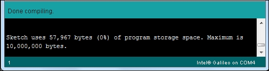
Verifying a sketch
This means your sketch has no errors, and that it is occupying 57,967 bytes of the total 10,000,000 bytes of maximum program storage space available.
Now, by clicking on the Upload button, you'll be able to run the sketch in your board. If everything went fine, you'll see a Transfer complete message in the console and an on-board LED blinking every second.
The whole idea behind this demo consists of exporting the pin 13, configuring it as an output, and then keep doing digital writes from high to low inside a loop.
The following code will explain this more clearly:
/*
  Blink
  Turns on an LED on for one second, then off for one second, repeatedly.

  Most Arduinos have an on-board LED you can control. On the Uno and
  Leonardo, it is attached to digital pin 13. If you're unsure what
  pin the on-board LED is connected to on your Arduino model, check
  the documentation at http://arduino.cc

  This example code is in the public domain.

  modified 8 May 2014
  by Scott Fitzgerald
 */
The pin 13 was selected because it is directly connected to the on-board LED you can see blinking. If you connect an LED to that I/O, you'll have them both blinking:
// the setup function runs once when you press reset or power the board
void setup() {
  // initialize digital pin 13 as an output.
  pinMode(13, OUTPUT);
}
// the loop function runs over and over again forever
void loop() {
  digitalWrite(13, HIGH);   // turn the LED on (HIGH is the voltage level)
  delay(1000);              // wait for a second
  digitalWrite(13, LOW);    // turn the LED off by making the voltage LOW
  delay(1000);              // wait for a second
The sketches always have two main functions—the setup and the loop. The setup function will only be called once, and it is commonly used for initial configuration. In this example, you can see the pinMode method being called inside this method, exporting the LED (connected to pin 13) for the application and setting its direction as OUTPUT.
Inside the loop method, you'll find that pin 13 is repeatedly being set from HIGH to LOW, and vice-versa. Those changes are made using the digitalWrite method, which is responsible for changing the pin voltage level from 0 V to 5 V and from 5 V to 0 V. The delay method helps the LED keep its state every second (1,000 ms) after a state change.
In this example, you'll be able to understand how to fade an LED. Plug in your resistor, LED, and jumper wires to the breadboard, as shown in the following figure:

The Fade example connection diagram
Connect one jumper wire from Galileo pin 9 (digital PWM) to one side of the resistor. The other side of the resistor should be connected with the anode of the LED (the longer lead). Finally, the LED cathode (shorter lead) should be connected to the Galileo ground.
Coming back to the IDE, you'll find this example sketch by navigating to File | Examples | 1.Basics | Fade. With the example loaded into your sketch, verify and upload it to your board.
As soon as the upload is complete, you should see the LED fading in and out repeatedly over time.
In the previous example, you were able to set two LED states, on and off, using the digitalWrite method. In order to have more states, we will need to use the analogWrite method. The LED seems to have more than two states. This happens because analogWrite uses a property named pulse with modulation (PWM). It accepts values from the range of 0 up to 255:
Looking at the code, we have:/*
 Fade

 This example shows how to fade an LED on pin 9
 using the analogWrite() function.

 This example code is in the public domain.
 */
int led = 9;           // the pin that the LED is attached to
Only pins with PWM are supported, Galileo has available the pins 3, 5, 6, 9, 10 and 11.
int brightness = 0;    // how bright the LED is
int fadeAmount = 5;    // how many points to fade the LED by

// the setup routine runs once when you press reset:
void setup()  {
  // declare pin 9 to be an output:
  pinMode(led, OUTPUT);
}
Every loop cycle, the amount of brightness is increased by 5 units until it reaches the PWM maximum of 255 or decreased by 5 units until it reaches 0:
// the loop routine runs over and over again forever:
void loop()  {
  // set the brightness of pin 9:
  analogWrite(led, brightness);

  // change the brightness for next time through the loop:
  brightness = brightness + fadeAmount;

  // reverse the direction of the fading at the ends of the fade:
  if (brightness == 0 || brightness == 255) {
    fadeAmount = -fadeAmount ;
  }
  // wait for 30 milliseconds to see the dimming effect
  delay(30);
}Sometimes, you need to have a bit more feedback about the operations you are doing, display some variables values, or just output something so that you can see your code flow. In such situations, printing to the Galileo serial port can be very helpful.
Using the fade LED demo, we can add some outputs so that we can understand what's happening.
The Serial.begin(baud_rate) method opens the Galileo serial port and sets its speed to the specified baud rate. You can then start writing using the Serial.print() and Serial.println() methods if you wish to change line at the end of the writing.
In your previous code, you can add the following lines:
/*
 Fade

 This example shows how to fade an LED on pin 9
 using the analogWrite() function.

 This example code is in the public domain.
 */

int led = 9;           // the pin that the LED is attached to
int brightness = 0;    // how bright the LED is
int fadeAmount = 5;    // how many points to fade the LED by

// the setup routine runs once when you press reset:
void setup()  {
Initialize the serial port and set up the data transfer baud rate to 9600:
  Serial.begin(9600);
  // declare pin 9 to be an output:
  pinMode(led, OUTPUT);
Print a line with a custom message to confirm that it is working:
  Serial.println("Setup is concluded!");
}

// the loop routine runs over and over again forever:
void loop()  {
Print the text keeping the "cursor" in the same line:
Serial.print("Brightness value is ");Print the brightness value and move the "cursor" to the next line:
  Serial.println(brightness);
  // set the brightness of pin 9:
  analogWrite(led, brightness);

  // change the brightness for next time through the loop:
  brightness = brightness + fadeAmount;

  // reverse the direction of the fading at the ends of the fade:
  if (brightness == 0 || brightness == 255) {
    fadeAmount = -fadeAmount ;
  }
  // wait for 30 milliseconds to see the dimming effect
  delay(30);
Tip
Downloading the example code
You can download the example code files from your account at http://www.packtpub.com for all the Packt Publishing books you have purchased. If you purchased this book elsewhere, you can visit http://www.packtpub.com/support and register to have the files e-mailed directly to you.
Verify and upload this code on your board. As soon as it is uploaded, click on the Serial monitor button, the one with a magnifying glass in the top right corner. In the serial Monitor window, select the 9600 baud rate, matching the same baud rate specified in the sketch. You should now be able to see the brightness values being displayed, as shown in the following screenshot:

The serial output