
In many public buildings, house gardens, or even common spaces such as restrooms, we can find lights that are triggered on when motion or presence is detected. These kinds of systems aim to save electricity by turning the lights on only when they are needed, not giving the chance of someone forgetting to turn them off.
In this chapter, we will create our own energy saving lighting system. We'll control a single AC powered lightbulb using a solid state relay, which will be operated by the Galileo considering sensorial data. You'll learn how to use the Arduino IDE to read digital and analog data from sensors. Finally, we'll build a web server to serve a web page, allowing you to control the whole system with it.
In this chapter, we will cover the following topics:
- Reading analog and digital inputs with the Arduino IDE
- Learning how to use a PIR sensor for motion detection
- Learning how to use a photoresistor to detect luminosity
- Controlling a solid state relay considering the collected data from sensors
- Using Galileo as a web server
- Controlling the whole system using a web page served by Galileo
This project will require some electronic and electrical equipment. We'll be building not only DC, but also AC circuits.
To be able to complete all the steps in this chapter, besides the Galileo board, you'll need the following material:
- A lightbulb, a lightbulb socket, and a power plug:

In this example, we'll be using an E27 lightbulb (220 V-240 V, 20 W, 160 mA) with the correspondent socket and a power plug. We'll be using a European C-type plug, supporting 220 V. If you want to use another type of plug, socket, or lightbulb, be sure that they are compatible, otherwise you'll need to do some adjustments to the circuits.
- A Passive infrared motion sensor:
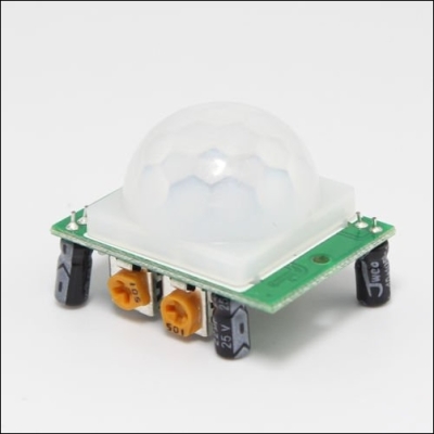
For the motion detection, we'll be using a generic HC-SR501 Passive Infrared (PIR) motion sensor supporting 5 V. This type of sensor can detect motion by measuring heat changes in its surroundings.
Note
If you need to purchase one, visit http://www.amazon.com/Great-Deal-HC-SR501-Infrared-Raspberry/dp/B00M1H7KBW.
- A photoresistor and a 10 kΩ resistor:
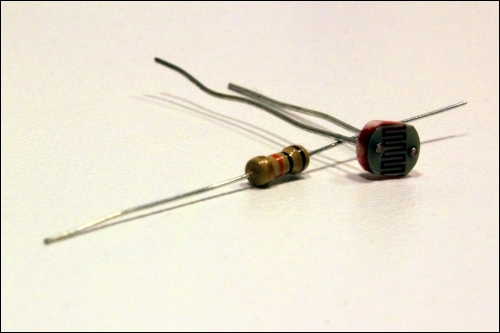
The photoresistor is a special type of resistor with a photoconductive property. The resistor value changes depending on the amount of light it is exposed to. It is a cheap option and a great addition to obtain input on the day's luminosity. You'll also need a resistor for the circuit. We'll use a 10 kΩ resistor, which is represented by the colors: brown, black, orange, and gold.
Note
If you need to purchase a photoresistor and a 10 kΩ resistor, you can order them at http://www.ebay.com/itm/3-x-Light-Photosensitive-Detector-Sensor-Switch-LDR-3-x-10k-Resistor-Arduino-/181585094020?hash=item2a4750a584.
- A solid state relay, four two-core cable and Y terminals:

To be able to control a 220 V lightbulb, we'll need to use a relay. A relay is a switch that is electrically controlled. It uses an electromagnet to mechanically pull two connections together and close that circuit. In this particular case, we will be using a solid state relay. It is also a switch, but it doesn't contain mechanical parts. Besides having a bigger lifetime than the electromechanical relay, it is safer to operate, considerably faster, but more expensive. We'll need one solid state relay (http://www.amazon.com/Bessky-TM-White-Controller-24-380V/dp/B00HIU8TSK) that can handle 220 V AC, being operated by 5 V DC. We'll also need a two-core cable (http://www.ebay.com/itm/2-Core-6A-Black-Power-Cable-0-75mm-Electric-Flexible-Mains-Car-Wire-/360465655261) long enough to connect the lightbulb socket to the relay and power plug. Using Y terminals (http://www.amazon.com/Absolute-USA-ST1210Y-Insulated-Connectors/dp/B00M4CZZJI) in the cables that will be connected to the relay will help make the wiring process easier and safer.
- A breadboard and some jumper wires:
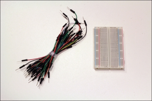
A small breadboard and a couple of male/male hookup wires will help you connect your sensors to the Galileo.
Note
If you need to purchase them, you can find them at http://www.amazon.com/microtivity-IB401-400-point-Experiment-Breadboard/dp/B004RXKWDQ.