8
High-Speed Maglev Transport
8.1 Electromagnetic and Electrodynamic Levitation
Magnetic levitation (maglev) can provide a super high-speed ground transport with a nonadhesive drive system that is independent of frictional forces between the guideway (track) and vehicle bogies. Maglev trains, a combination of contactless magnetic suspension and linear motor technology, realizes super-high-speed running, safety, reliability, low environmental impact, and minimum maintenance. Two maglev transportation technologies emerged in the early 1970s: electromagnetic (EML) levitation, which utilizes attractive forces of electromagnets with controlled air gap, and electrodynamic (EDL) levitation, which utilizes repulsive forces and superconductivity.
Nowadays, the target speed of ground transport of economic superpowers is minimum 400 km/h. Research done in Germany and Japan shows that vehicles suspended magnetically and propeled by linear motors are the optimum solution to modern transport problems. Magnetic levitation trains can run at speeds up to 550 km/h, consuming less energy than aircraft and road vehicles. Speed above 500 km/h can also be achieved by wheel-on-rail trains (TGV Atlantique set the world speed record of 574.8 km/h in 20071), but this kind of propulsion is not adhesion free and emits a high level of acoustic noise.
In EML levitation systems (Fig. 8.1), the attraction force between the steel yoke (guidance) and electromagnet poles lifts the vehicle. The electromagnet is fixed to the undercarriage. The current of the electromagnet is automatically controlled in proportion to the air gap. Assuming that the magnetic permeability of steel tends to infinity, there is no fringing effect and no leakage fluxes, the inductance of the electromagnet winding as a function of the air gap is simply
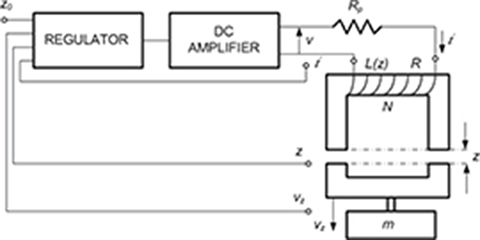
Fig. 8.1. Electromagnetic levitation system: zo — required air gap, z — actual air gap, vz — speed of the electromagnet in the z-direction, m — mass of yoke (part being suspended).

Fig. 8.2. Electrodynamic levitation system: a — coil width, l — coil length, d — aluminum plate thickness, g — air gap.
where the inductance at nominal air gap is
In eqns (8.1) and (8.2), μo is the magnetic permeability of free space, A is the area of the air gap under a single pole of the electromagnet, N is the number of turns of the coil, z is the axis perpendicular to the electromagnet pole shoes, and g is the nominal air gap. The attraction force can be found using eqn (1.15), Chapter 1. However, this equation does not include the magnetic voltage drop in the ferromagnetic core (magnetic saturation). With the magnetic flux path in the ferromagnetic core being included, eqn (1.15) for attraction force of an U-shaped electromagnet takes the form
where lF e is the mean path of the magnetic flux in the ferromagnetic core including armature, and μr is the relative magnetic permeability of the ferromagnetic core (assuming the same magnetic flux in each portion of the core) for a given magnetic field intensity.
An EML levitation system needs a control system. When the air gap between the pole and the yoke increases, the current in the coil of the electromagnet must increase. When the air gap decreases, the current must decrease. In practice, to keep the required air gap z = g = constant (about 10 mm), a control system with three feedback signals is used: displacement z, linear velocity vz in the z direction, and current i.
In EDL levitation systems (Fig. 8.2), the repulsive forces between the SC electromagnet mounted on the undercarriage and aluminum plates or short circuited coils (guidance) fixed to the guideway are used. The air gap (100 to 300 mm) is much higher than that in EML levitation systems. Owing to the large air gap, the electrodynamically levitated trains can operate in severe climates with heavy snowfalls, ice formations, and white frost formations. The repulsive force between the d.c.-fed coil moving with velocity v and a nonferromagnetic conductive plate placed below the coil can be calculated using Hannakam’s [82] formula, which has been modified by Guderjahn et al, [73] i.e.,
If the thickness of conductive plate d < δ
and if the thickness of conductive plate d > δ
The parameter
is the equivalent depth of penetration of the electromagnetic field into the nonferromagnetic conductor with electric conductivity σ. The length of electromagnetic wave is λ = v/f ≈ a [73]. The coefficient 1/(1 + k2) in eqn (8.4) can also be replaced by exp{−ξ/[1 + 2(g/l)3/2]}, where ξ = [4π/(μovσg)]1/2. The coil moving with velocity v is subject to the drag (braking) force
More detailed discussions of eqn (8.4) are given in [29, 73].
8.2 Transrapid System (Germany)
8.2.1 Background
Research in transportation engineering carried out in Germany in the 1960s and early 1970s was focused on the energy consumption, costs, safety and impact on environment by trains, road cars, aircraft, and maglev vehicles [140]. Fig. 8.3a shows energy consumption per passenger per 1 km against speed of trains, cars, aircraft, and magnetic levitation trains [140]. The speed of magnetic levitation trains is less than that of airplanes, but the energy consumption is much lower. Maglev trains can enter city centers, and no time is wasted to travel from home to the airport and vice versa. Other advantages include low level of noise (Fig. 8.3b), high level of safety of riding (Fig. 8.3c), high comfort of riding, easy maintenance, low land absorption, adaptability to the landscape due to the high gradability of 10% and the small curvature radii of 2.25 km at 300 km/h, and no pollution to the natural environment.
8.2.2 Propulsion, Support, and Guidance
The Transrapid maglev system (Fig. 8.4) uses attractive forces produced by U-shaped electromagnets (EML levitation system) with current control and long-armature three-phase LSMs. The levitation electromagnets attached to the vehicle bogie are also the excitation electromagnets for LSMs. Another set of on-board electromagnets, i.e., guidance electromagnets, provides lateral stabilization. No SC coils are used. The support and guidance electromagnets and vehicle electric system are supplied by contactless linear generators.
Long-armature cores of LSMs are placed in two parallel rows at both sides of the guideway. Each armature has a laminated core with slots as in a typical a.c. linear motor. Laminations are stamped from an adhesive coated steel tape. For the manufacturing of the armature windings, not only electrical and geometrical conditions but also efficient large-scale production and assembly have been taken into account. The three-phase winding is made of a cable with synthetic elastometer insulation pre-shaped with small radii. Typical cable construction used in the South Loop of Emsland Transrapid Test Facility is a multistrand aluminum conductor of 300 mm2 cross section. The cable winding is fixed in the armature stack slots with the aid of winding casings (snap locks).
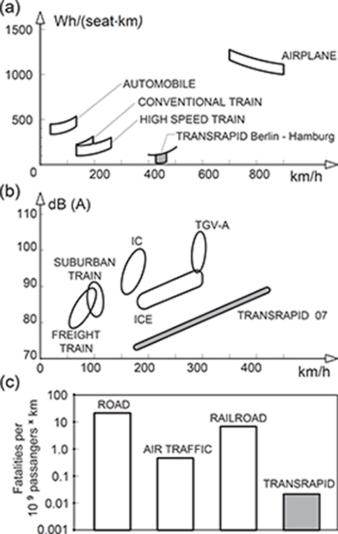
Fig. 8.3. Comparison of passenger transportation systems: (a) energy consumption per passenger per kilometer against speed; (b) maximum noise level at 25 m distance (IC — intercity train, ICE — intercity express; TGV-A — TGV Atlantique); (c) safety analysis — transportation system risk. Courtesy of Thyssen Transrapid System, GmbH, München, Germany.

Fig. 8.4. (see color insert.) Transrapid 07 Europa (Emsland Transrapid Test Facility). Photo courtesy of Thyssen Transrapid System, GmbH, München, Germany.
The excitation system of LSMs and EML suspension of vehicles are integrated and consist of vehicle-mounted U-shaped electromagnets. Interaction of electromagnet poles and laminated cores of LSMs produce attractive forces that lift the vehicle. An electronic control system ensures a constant uniform air gap of about 10 mm (see also Fig. 8.1). Other sets of E-shaped electromagnets, so called guide electromagnets, face the side steel rails and provide lateral guidance (stabilization). Every section of the vehicle is equipped with 15 autonomous support and 13 autonomous guidance electromagnets. The cross section of the support, guidance, and propulsion system is shown in Fig. 8.5. There is a large clearance between the top of the guideway and bottom of the vehicle, so that the maglev train can also levitate over obstacles or a snow cover on the guideway.
The attractive and lateral forces are controlled by currents of support and guide electromagnets, respectively. The thrust can be varied only by the magnitude and phase angle of the armature current. By reversing the phase sequence, LSMs become synchronous generators, which then provide electrodynamic braking forces without any contact. The braking energy is fed back to the network. The long-armature LSM is characterized by the following features [221]:

Fig. 8.5. Cross section of the support, guidance, and propulsion system: 1 — support electromagnet, 2 — LSM armature stack with windings, 3 — linear generator windings, 4 — guidance magnet, 5 — eddy-current brake electromagnet, 6 — support skids, 7 — Inkrefa sensor (vehicle location), 8 — levitation bogies, 9 — cabin suspension, 10 — pneumatic spring. Courtesy of Thyssen Transrapid System, GmbH, München, Germany.
As a result of the combination of the suspension and drive systems, the mass of the vehicle determines the excitation of the LSM.
The three-phase armature winding is fed from VVVF solid-state converters installed in substations that are distributed along the line.
Control of the tractive effort keeps the air gap flux constant.
Leakage reactance of the armature winding and of the feeder cable primarily determines the LSM characteristics since the individual sections of the armature windings are longer than the vehicle.
To reduce the energy consumption, the long-armature LSM of the guideway is divided into sections. Only that section in which the vehicle is running is switched on.
8.2.3 Guideway
The T-shaped elevated guideway has two rows of long stator (armature) LSMs with laminated cores on its bottom and lateral steel rails for guidance. The LSM armature core serves also as a suspension rail. Because the vehicle clasps its guideway, derailment is impossible. The construction of the Transrapid guideway and any other maglev train guideways demands
minimum restrictions on the use of the existing terrain,
good visual blending into the landscape,
low noise level,
low maintenance requirements and long life,
protection against effects of the environment and vandalism.
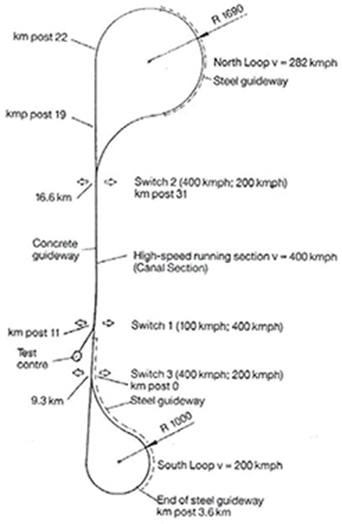
Fig. 8.6. The Emsland test line. Courtesy of Thyssen Transrapid System, GmbH, München, Germany.
The 31.5 km long Transrapid test line with two loops is located in the Emsland region (Fig. 8.6). The first 20.5 km section began operating in 1985. The Emsland Transrapid Test Facility (TVE) was completed in 1987. About 20 km of TVE was erected as an elevated concrete guideway, about 5 km as an elevated steel guideway, and the rest as a ground-level guideway.
8.2.4 Power Supply
The Emsland Transrapid Test Facility is supplied with power from the 110 kV public system (Fig. 8.7). The d.c. link circuit is supplied with 2.6 kV, 2×33 kA through a 110/20 kV transformer and two 20/1.2 kV rectifier transformers connected in parallel. The rectifier transformers each supply two connected-in-series fully controlled rectifier bridges to obtain a twelve-phase group. Smoothing reactors and protective d.c. high-speed circuit breakers are arranged at the input of the d.c. link circuit. The d.c. link voltage is converted by two PWM inverters into a three-phase VVVF changing from 0 to 2027 V and 0 to 215 Hz. The maximum LSM current is 1.2 kA. The energy consumption from the substation for the prototype vehicle is about 60 Wh/(seat×km) at constant speed of 400 km/h.

Fig. 8.7. Basic circuit of LSMs power supply of the Emsland Transrapid Test Facility. Courtesy of Thyssen Transrapid System, GmbH, München, Germany.
8.2.5 Vehicle
Specification data of the EML levitation vehicle Transrapid 07 introduced by Thyssen Henschel in 1988 at the International Traffic Fair IVA’88 in Hamburg are presented in Table 8.1. A two-section train with passenger capacity 136 to 298 persons is formed only with two end cars. The measured aerodynamic drag for two-section vehicle at 400 km/h was originally 35.5 kN and then reduced to 33 kN.
Table 8.1. Technical data of Transrapid 07. Courtesy of Thyssen Transrapid System, GmbH, München, Germany

The support and guidance system of the Transrapid 07 is characterized by a chain-like arrangement of electromagnets attached to the hinge points and adjustable in two degrees of freedom with a secondary suspension system between the levitating bogie and car body [221]. To minimize the unsprung masses, the support electromagnets are suspended horizontally, and the guiding electromagnets are suspended vertically through linear guides and rubber spring elements.
The electromagnet windings are fed with variable current commanded by the air gap control system by separate choppers for support and guidance. The power for the electromagnets and auxiliary equipment of the vehicle is produced by linear generators. Each support electromagnet is fitted with two five-phase symmetrical linear generators (Fig. 8.8). The on-board boost converters adjust the voltage according to the frequency, which increases in proportion to the speed[221].

Fig. 8.8. Linear generator of Transrapid vehicles. 1 — armature (guideway), 2 — pole of a suspension electromagnet (vehicle), 3 — winding of the linear generator.
The speed record of 501 km/h was achieved by Shanghai Transrapid in November 2003. Prior to that, the speed record was 450 km/h set by Transrapid 07 in June 1993.

Fig. 8.9. (see color insert.) Transrapid 08. Photo courtesy of Thyssen Transrapid System, GmbH, München, Germany.
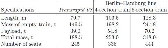
Further optimization of the Transrapid 07 was carried out to lower the manufacturing cost and to improve the ride comfort and safety. The new vehicle Transrapid 08 shown in Fig. 8.9 [234] was a prototype of the fleet for the Berlin-Hamburg route (Table 8.2).
Table 8.2. Technical data of Transrapid 08. Courtesy of Thyssen Transrapid System, GmbH, München, Germany
8.2.6 Control System of Electromagnets
The mechanical clearance between suspension electromagnets and guideway rails is kept constant by means of the electromagnet current control system (Fig. 8.10). The contactless gap sensor integrated in the pole face of the support electromagnet determines an electrical signal proportional to the distance between the electromagnet and steel rail. From the measured signals proportional to the electromagnet current, acceleration, and air gap, the rated electromagnet current is adjusted in the control loop and transmitted to the chopper as input signal.
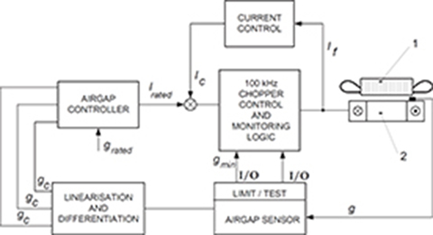
Fig. 8.10. Air gap control system of Transrapid vehicles. 1 — armature (guideway), 2 — suspension electromagnet (vehicle).
8.2.7 The Future of Transrapid System
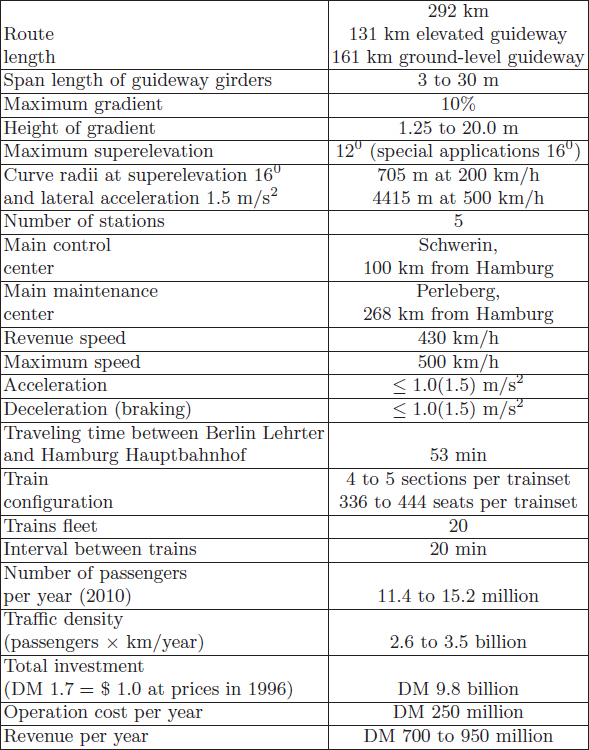
In March 1994, the plan of construction of the 292 km maglev line from Berlin via Schwerin (main control center) to Hamburg (Table 8.3) was approved by the German Federal government. Five stations have been planned, i.e., Berlin Lehrter Bahnhof, Berlin Spandau, Schwerin, Hamburg Moorfleet, and Hamburg Hauptbahnhof. This decision was made due to plans to transfer the lower house of parliament (Deutsche Bundestag) and part of the German government to Berlin. The route Bonn–Berlin had also been investigated, but it was deferred due to unacceptable high costs [237].
For a five-section train, the energy consumption had been foreseen as follows [147]:
33–38 Wh/(seat×km) at constant speed 300 km/h;
57–65 Wh/(seat×km) at constant speed 430 km/h;
158–182 Wh/(seat×km) at acceleration from 0 to 430 km/h in 3.7 min (distance 16.5 km);
219–252 Wh/(seat×km) at acceleration from 0 to 300 km/h in 1.9 min (distance 4.8 km).
For comparison, IC trains consume 56 Wh/(seat×km), and TGV superexperss train consumes 108 Wh/(seat×km) at constant speed.
The financial concept was based on the separation of the guideway and operator companies. The federal government (Deutsche Bahn AG) was responsible for the financing and construction of the guideway (DM 6.1 billion in 1996). The operator companies, i.e., Adtranz (ABB Daimler Benz), Siemens and Thyssen Transrapid System, GmbH, were supposed to finance and construct the operating system (DM 3.7 billion in 1996). The total investment was estimated as DM 9.8 billion as calculated in 1996. It has been assumed that the Berlin–Hamburg maglev line will be completed by 2005. The concept of Maglev link between Berlin and Hamburg was canceled in 2001.
Table 8.3. Berlin–Hamburg Transrapid line.
Shanghai was chosen as the site of the construction of the Transrapid project in June 2000. Shanghai’s Maglev train (Fig. 8.11) opened for service in November 2004, and makes the 32 km trip between Pudong Airport (PVG) and downtown Shanghai (Longyang Road for transfer to Metro Line 2) in only 8 min. The approved speed is 430 km/h.

Fig. 8.11. (see color insert.) Transrapid in Shanghai, China.
The new 175 km Transrapid line from Shanghai to Hangzhou (Zhejiang province) was approved in 2006. With trains traveling at up to 430km/h, the projected journey time was 27 min.
Chinese Chengdu Aircraft Industry Group is developing its own maglev train. The design of new trains does not use German technology. This part of the National 863 Project’s Dolphin was for developing high-speed maglev vehicles (500 km/h) in 2008, and it was put into production in Chengdu. In 2009, Tongji University (Jiadong Campus) in Shanghai built a 1.7 km test track as a part of the Dolphin project.
The Transrapid was considered by the UK government for a 500 km/h link between London and Glasgow, via Birmingham, Liverpool/Manchester, Leeds, Teesside, Newcastle and Edinburgh, but was rejected in 2007.
8.2.8 History of Transrapid Maglev System in Germany
1922 — First consideration of EML levitation train by H. Kemper.
1939-43 — Basic work on EML levitation train with jet engine at the Aerodynamic Test Establishment in Goettingen.
1969 — Construction of the first practical EML levitation model vehicle Transrapid 01 (TR 01) by Krauss–Maffei, Münich. Support and guidance according to H. Kemper. Propulsion by a short-armature linear motor.
1971 — First passenger-carrying EML levitation prototype vehicle built by Messerschmitt–Boelkow–Blohm (MBB) tested on a 660 m long track at Ottobrun. Propulsion by a short-primary LIM. Maximum speed 90 km/h. Transrapid 02 operated by Krauss-Maffei on 0.93 km track with EML levitation support and maximum speed 164 km/h.
1972 — Transrapid 03 operated by Krauss-Maffei on 0.93 km track with EML levitation support and short-primary LIM at maximum speed 140 km/h. Start of the development of EDL levitation system with SC coils by AEG-Telefunken, Brown Boverie & Cie AG (BBC) and Siemens. Construction of a 0.9 km circular track and EET 01 test vehicle at Enlargen.
1973 — Transrapid 04 operated by Krauss Maffei on 2.4 km track with EML levitation support.
1974 — Merger of Krauss-Maffei and MBB, forming Transrapid EMS. Construction of Komet vehicle with EML support, rocket engines, and maximum speed 401.3 km/h by MBB.
1975 — First practical vehicle HMB 1 with long armature LSM and EML levitation support introduced by Thyssen Henschel, Kassel.
1976 – First passenger-carrying vehicle HMB 2 with long-armature LSM and EML levitation support introduced by Thyssen Henschel, Kassel.
1977 — Federal Ministry of Research and Technology decides to develop EML levitation systems and abandon EDL systems.
1978 — Foundation of the Magnetbahn Transrapid consortium by AEG-Telefunken, Brown Boveri & Cie AG, Dyckerhoff & Widmann, Krauss-Maffei, MBB, Siemens AG and Thyssen Industrie AG Henschel.
1979 — Emsland Transrapid Test Facility (TVE) construction work starts. International Traffic Fair (IVA’79) in Hamburg with first-in-the-world operation of Transrapid 05 vehicle (EML and LSM) authorized to carry passengers at speed 75 km/h.
1980 — Construction of Transrapid 06. Emsland Transrapid Test Facility starts.
1981 — Foundation of Gesellschaft für Magnetbahnsysteme Transrapid International with Krauss-Maffei, Messerschmitt Boelkow Blohm, and Thyssen Industrie AG Henschel as partners.
1983 — First operation of Transrapid 06 (EML and LSM).
1984 — Opening of the first 21.5 km section of Emsland Transrapid Test Facility (North Loop). Transrapid 06 achieves the speed of 302 km/h.
1987 — Completion of the Emsland Transrapid Test Facility (South Loop). Transrapid 06 achieves the speed of 406 km/h.
1988 — Transrapid 06 achieves the speed of 412.6 km/h. Transrapid 07 at the International Traffic Fair (IVA’88) in Hamburg.
1992 — Maglev link between Berlin and Hamburg in unified Germany indentified.
1993 — Transrapid 07 achieves the speed record of 450 km/h.
1994 — Maglev link between Berlin and Hamburg approved by parliamentary bodies.
1995 — Public demonstration of Transrapid 07 in Emsland starts.
1999 — First tests of Transrapid 08.
2000 — Shanghai was chosen as the site of the construction of Transrapid.
2001 — Maglev link between Berlin and Hamburg cancelled.
2003 – Speed record of 501 km/h was achieved by Shanghai Transrapid in November 2003.
2004 — Shanghai Transrapid line opened for service between Pudong Airport and downtown Shanghai.
2006 — Transrapid train collided with a maintenance vehicle at 170 km/h on Emsland elevated test track in Lathen (22 September). The accident was caused by human error. There were 23 fatalities and 10 severe injuries.
2006 — Extension of the 175-km Transrapid line from Shanghai to Hangzhou is approved by the Chinese State Council. Over 7 million passengers traveled with the Transrapid in Shanghai.
2007 — Delivery of the 1st section of the Transrapid 09 to the Transrapid test facility in Emsland, Germany
8.3 Yamanashi Maglev Test Line in Japan
8.3.1 Background
The population of greater Tokyo, including Chiba, Kanagawa and Saitama prefectures, is now about 40 million inhabitants or almost one third of the total population of Japan (127.6 million). Most of the governmental, administrative, business, financial, and cultural institutions are located in Tokyo. To correct the imbalance created by the overcentralization of people, power, and resources, it is essential that the political, economic, and social functions served by the greater Tokyo metropolitan area be partially relocated and distributed through the nation.
At the present time, Tokyo and Osaka are connected by the Tokaido Shinkansen superexpress trains with the maximum speed of 300 km/h, carrying about 368,000 passengers in 283 trains a day, which is nearly the limit of this line [159]. There is a strong demand on another environmental friendly transportation system with higher speed. The Chuo Shinkansen, a new transportation artery between Tokyo and Osaka using superconducting (SC) technology, is expected to be implemented in the second decade of the 21st century. New Chuo Shinkansen trains achieving speed over 500 km/h are necessary to unload the limited capacity of the Tokaido Shinkansen line, preserve the natural environment, and limit the risks from natural disasters.
8.3.2 Location of Yamanashi Maglev Test Line
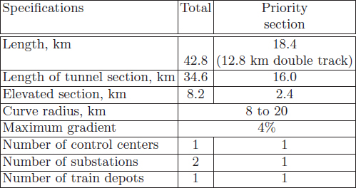
The Yamanashi Maglev Test Line is a part of the future Chuo Shinkansen line between Tokyo and Osaka. It is a joint project of the Central Japan Railway Company (JR Central), Railway Technical Research Insitute (RTRI) and Japan Railway Construction Public Corporation, which was approved by the Ministry of Transport in 1990. The 42.8 km test line will be constructed between Sakaigawa village, Higashi–Yatsushiro district, and Akiyama village, Minami–Tsuru district in Yamanashi Prefecture, west from Tokyo. At present, an 18.4 km Katsunuma-budokyo–Ohtsuki section has been completed (Figs 8.12 and 8.13). The maximum planned speed is 550 km/h (operation speed 500 km/h), minimum curve radius is 8 km, maximum gradient is 4%, and distance between the centers of adjacent parallel guideways is 5.8 m. A 12.8 km section is a double-track line where the dynamics of two trains passing each other at a relative speed of about 1000 km/h will be studied. Other specifications are given in Table 8.4. The cost of the 18.4 km test line, power conversion substation, control center, train, and train depot is about 230 billion yen (1996).

Fig. 8.12. Yamanashi Maglev Test Line: (a) outline, (b) profile. Courtesy of Central Japan Railway Company and Railway Technical Research Institute, Tokyo, Japan.
8.3.3 Principle of Operation
The experimental maglev train MLX01 for the Yamanashi Maglev Test Line is suspended on the principle of EDL levitation where the repulsive forces are produced between stationary short-circuited coils and moving SC electromagnets. The track is U-shaped and embraces the bottom of the vehicle. At each side of the track, nonpowered short-circuited coils serving both as levitation and lateral guideway coils are mounted in a vertical position. The vehicle is equipped with SC electromagnets. In addition, a three-phase propulsion vertical winding fed with three-phase current is installed at each side of the track, which, together with the train electromagnets, forms an air-cored LSM. The three-phase stationary winding produces a traveling magnetic field and corresponds to the armature winding of a conventional synchronous motor. The vehicle’s SC electromagnets correspond to the excitation system of a synchronous machine. When the train, propelled by the LSM, passes short-circuited coils at high speed, currents induced in these coils together with the magnetic field excited by SC electromagnets produce strong repulsive and lateral stabilization forces on the vehicle. The same SC electromagnets are used both for levitation, lateral guidance, and propulsion.
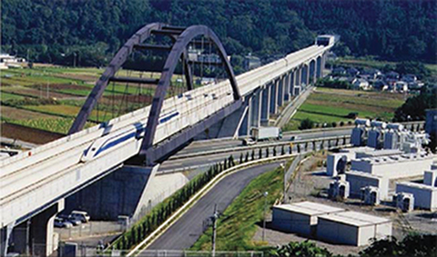
Fig. 8.13. (see color insert.) Yamanashi Maglev Test Line: Ogatayama Bridge over the Chuo Expressway. Courtesy of Central Japan Railway Company and Railway Technical Research Institute, Tokyo, Japan.
Table 8.4. Yamanashi Maglev Test Line: data of experimental track. Courtesy of Central Japan Railway Company and Railway Technical Research Institute, Tokyo, Japan
8.3.4 Guideway
The arrangement of ground and vehicle windings is shown in Fig. 8.14. Both propulsion coils and levitation–guidance coils are attached to the concrete side walls of the guideway (Fig. 2.25).

Fig. 8.14. Arrangement of propulsion, levitation-guidance and excitation coils: 1 — propulsion, front side, 2 — propulsion, reverse side, 3 — 8-shaped levitation and guidance coils, 4 — excitation coil (on-board SC electromagnet) [239].
All ground coils are made of aluminum conductors insulated with polyester (epoxy) resin. Propulsion coils have dimensions approximately 1.42 × 0.6 m. The 8-shaped levitation and guidance coils have dimensions approximately 0.9 × 0.9 m and are attached to the surface of the three-phase two-layer propulsion winding. The levitation and guidance coils consist of two sections: for levitation and for lateral stabilization (guidance) of the vehicle (Fig. 8.15). The guidance sections facing each other at two opposite sides are electrically connected under the track, constituting a null-flux connection (Fig. 8.16). If the train deviates from the center of the guideway, the deviation is reversed by the attractive forces of the superconducting electromagnet on the distant side of the guideway and repulsive forces on the opposite (near) side.
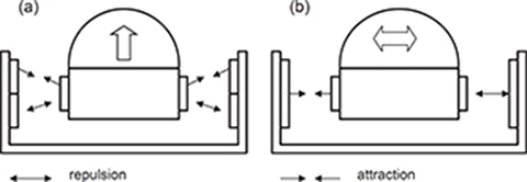
Fig. 8.15. Operation of 8-shaped coils: (a) levitation, (b) lateral stabilization (guidance) of the vehicle [239].
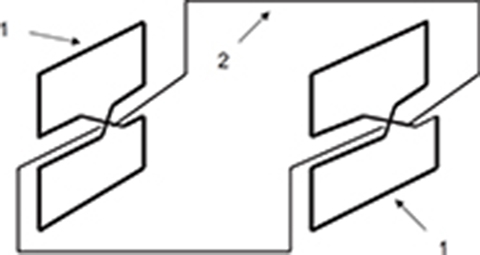
Fig. 8.16. Null-flux connection of levitation and guidance coils. 1 — coils, 2 — null-flux cable [239].
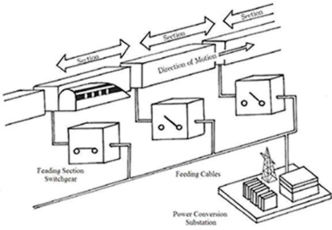
Fig. 8.17. Feeding system of propulsion winding sections. Courtesy of Central Japan Railway Company and Railway Technical Research Institute, Tokyo, Japan.
In order to achieve passenger comfort when traveling at very high speeds, the ground coils must be installed more precisely than Shinkansen rails. The accurate attachment, easy construction, and simple maintenance require three types of guideways: (a) panel type, (b) side-wall beam type, and (c) direct attachment type (Chapter 2).
To save energy, a group of propulsion coils are connected in series and create a winding section. Only those sections carrying the train are powered through the feeding section switchgears (Fig. 8.17).
Table 8.5. Specification data of MLX01 Maglev Trains. Courtesy of Central Japan Railway Company and Railway Technical Research Institute, Tokyo, Japan

8.3.5 Vehicle
The MLX01 test vehicle (Table 8.5), consisting of two end cars and one intermediate car, is shown in Fig. 8.18 and Fig. 8.19 [239]. The car body has been designed to obtain a mass reduction and provide a comfortable interior. Both the mass and cross section of the car are smaller than those of existing Shinkansen trains to reduce the air drag and improve dynamic performance. The structure of the body using the aircraft and rolling stock technologies has a light weight and enough strength to endure the repeat of large pressure fluctuations when passing through tunnels. Two types of nose shapes, i.e., double cusp and aerowedge, were developed, which considerably reduce air drag and aerodynamic noise.

Fig. 8.18. Outline of the MLX01 Maglev Train. Courtesy of Central Japan Railway Company and Railway Technical Research Institute, Tokyo, Japan.

Fig. 8.19. (see color insert.) Double-cusp-shaped head car (facing Koufu) of the MLX01 Maglev Train at Expo 2005, Aichi Prefecture, Japan. Courtesy of Central Japan Railway Company and Railway Technical Research Institute, Tokyo, Japan.
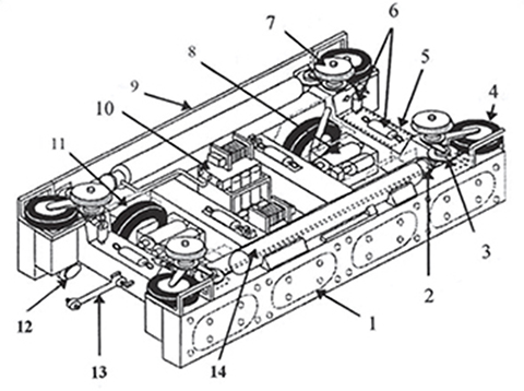
Fig. 8.20. Bogie of Yamanashi Maglev Test Line Vehicle: 1 — SC magnet, 2 — helium refrigerator, 3 — guiding stopper wheel, 4 — guiding gear, 5 — oil reservoir tank, 6 — dampers, 7 — air spring, 8 — hydraulic pressure unit, 9 — side cover, 10 — helium compressor, 11 — landing gear, 12 — emergency landing wheel, 13 — longitudinal anchor (to car body), 14 — liquid helium and nitrogen tanks. Courtesy of Central Japan Railway Company and Railway Technical Research Institute, Tokyo, Japan.
The bogie, on which the SC magnets are mounted, serves to transmit the propulsion and levitation forces to the vehicles (Fig. 8.20). A refrigeration system for freezing the helium is also mounted on the bogie. To improve traveling comfort, pneumatic springs for car body suspension and vibration control devices are incorporated in some bogies.
The bogie is fitted with landing and guide gear wheels that are necessary when traveling at low speeds. Hydraulic apparatus are used for raising and lowering these wheels.
Landing gears have been developed taking durability and mass reduction into consideration. Disk brakes and rubber tires are now capable of use at speeds over 500 km/h. To follow the track center at low speeds, the train is equipped with side guide gear wheels of smaller diameter than landing gear wheels.
The speed record of 581 km/h on the Yamanashi Maglev Test Line was achieved in 2003 (manned vehicle).
8.3.6 Superconducting Electromagnet
Light and strong SC electromagnets are carried on bogies of the MLX01 maglev trains (Fig. 8.20). There are eight SC coils per experimental vehicle, four at each side. The structure of the SC electromagnet (Chapter 2) prevents the so-called quench effect (superconducting-to-normal transition) and reduces internal excess heat. Supercomputer simulations of electromagnetic disturbances and mechanical vibration have been made to understand better these parasitic phenomena. The heat generation within the cryostat housing the SC coils has been quantified to establish countermeasures. Both the cryostat and on-board refrigeration system to reliquefy the helium gas vaporized within the cryostat are light and robust.
8.3.7 Power Conversion Substation
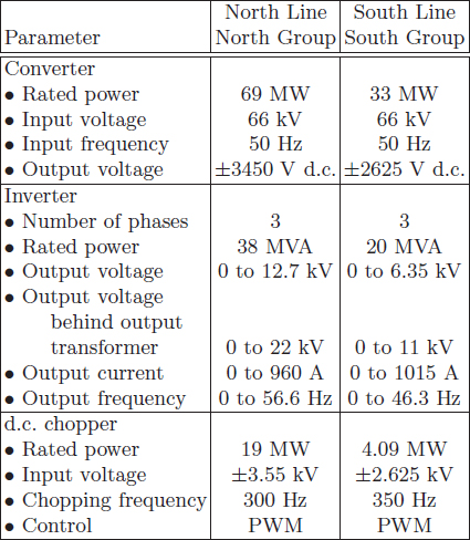
There are two groups of converters identified according to location on the substation yard and lines to be fed: North Line Group and South Line Group (Table 8.6). The power conversion substation (Fig. 8.21) converts electric power from 154 kV into 0 to 22 kV, 0 to 56.6 Hz (North Line Group) and 0 to 11 kV, 0 to 46.3 Hz (South Line Group) suitable for the velocity and acceleration or deceleration of the maglev train. At the frequency f = 56.6 Hz and pole pitch τ = 1.35 m (Tables 8.5 and 8.6), the maximum train velocity is vmax = 2fτ = 2 × 56.6 × 1.35 = 152.82 m/s ≈ 550 km/h. At f = 46.3 Hz, the maximum velocity is 450 km/h.
The main step-down transformer is rated at 60 MVA, 154/66 kV. The North Line Group consists of a 69 MW thyristor converter and 38 MVA GTO inverter with 500 Hz PWM. The South Line Group consists of 33 MW GTO converter with 350 Hz PWM and 20 MVA GTO inverter with 300 Hz PWM. High-power 4.5 kV, 4 kA GTO devices have been used [136].
Thus, the Yamanashi Maglev Test Line uses one of the largest inverters in the world. The inverter output current must be high (about 1 kA) because the insulation system of ground coils can withstand only limited voltage level. To reduce the input harmonic current at low speed operation and improve the power factor, converters are of multibridge structure.
Each group of three-phase inverters feeds three sections of the North Line and three sections of the South Line. The North Line with maximum speed of 550 km/h is fed with 22 kV. The South Line with maximum speed of 450 km/h is fed with 11 kV. The feeding section switchgears turn on and off each time the train passes by. Vacuum switches have been developed for endurance through over one million test operations.
Table 8.6. Specifications of power converters. Courtesy of Central Japan Railway Company and Railway Technical Research Institute, Tokyo, Japan
8.3.8 Brakes
The braking system of the prototype maglev train consists of ground-based brakes and on-board brakes.
The ground-based brakes incorporate regenerative braking and rheostatic braking. During regenerative braking, the current is reversed and returned to the power system. In rheostatic braking, the LSM operates as a generator and the kinetic energy of the train is converted into electric energy dissipated in the braking resistor.
The on-board brakes constitute a backup. To achieve a stable braking force from very high speed to standstill, two kinds of on-board brakes are installed. In high-speed range, aerodynamic brakes are effective, while in middle to low-speed range, the train is brought to a halt by built-in-wheel disk brakes (Fig. 8.22).
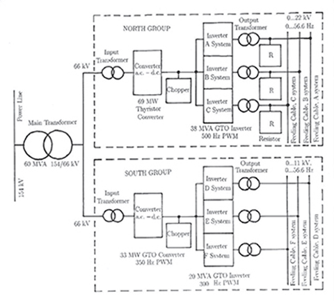
Fig. 8.21. Block diagram of power conversion substation [239].
8.3.9 Boarding System
An indoor type passenger platform has been designed (Fig. 8.23). The boarding system aligns with the passenger door in order to guide the passengers during boarding and provides a magnetic shielding. A narrow section of the guideway wall (where guide tires have a contact) facing the train door can fold down to allow passengers to board.
In order to make the interior of the passenger cabin more spacious while providing extra smoothness on the exterior of the cars and make them more airtight, special upward-sliding doors have been designed. Doors have been equipped both with infrared and contact sensors that sense passengers getting on and off the train, thus eliminating the danger of doors accidentally closing.
8.3.10 Control System
The experimental maglev train is operated automatically by ground-based control equipment. The whole control system (Fig. 8.24) consists of the three following systems: (a) traffic control, (b) safety control, and (3) drive control system. The train operation control center is located in the station building.
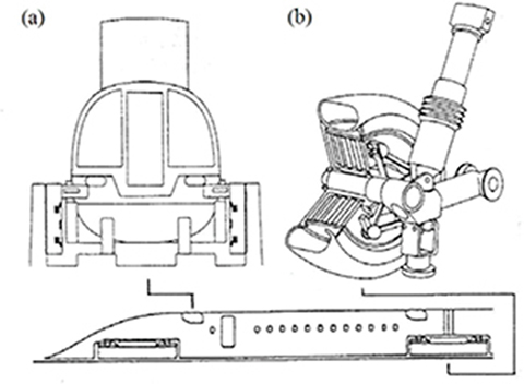
Fig. 8.22. On-board brakes: (a) aerodynamic brake, (b) disk brake. Courtesy of Central Japan Railway Company and Railway Technical Research Institute, Tokyo, Japan.

Fig. 8.23. Passenger boarding system. Courtesy of Central Japan Railway Company and Railway Technical Research Institute, Tokyo, Japan.
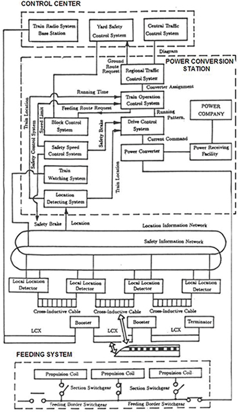
Fig. 8.24. Operation system of the experimental Yamanashi Maglev Test Line. Courtesy of Central Japan Railway Company and Railway Technical Research Institute, Tokyo, Japan.
Traffic control system
The traffic control system comprises the central traffic control system, the regional traffic control system, and the train operation control system. The central traffic control system generates a schedule of all trains, and the regional traffic control system regionally details it. The train operation system controls each train according to the direction of the regional traffic control system. The traffic control system also monitors all trains on the whole line.
Safety control system
The safety control system monitors the location and velocity of trains at all times and generates an acceptable speed limit for each train. Only within this limit are the traffic control system and the drive control system allowed to work. If the train runs out of this acceptable limit, the safety control system outputs the command of the safety brake and stops the train safely.
Since the maglev train is controlled on the ground, the safety control system uses cross-inductive cable installed along the whole line to detect the position of the train with high precision within several centimeters.
Drive control system
The drive control system corresponds to the driver in the conventional railway system. This system takes the running (rolling, gradient, acceleration, curve, and air) resistance and riding comfort into account and enforces the running pattern generated by the train operation system with the power electronics converters. It also switches on and off the section switchgears according to the position of the train.
8.3.11 Communication System
One leaky coaxial cable (LCX) per track has been installed for the train radio communication system. The train radio system uses millimetric waves from 30 to 300 GHz.
8.3.12 Experiments
The following experiments are carried out on Yamanashi Maglev Test Line:
Basic running tests, i.e., levitation running tests, wheel running tests, speed increasing tests, maximum speed (approximately 550 km/h) verification tests
General functional tests, i.e., high-speed passing tests, tunnel entering tests, substation crossover tests, multiple train control tests, emergency tests, etc.
Reliability verification tests, i.e., high-speed continuous running tests, transportation capability verification tests, etc.;
Other verification tests such as passenger physiology confirmation tests, station facilities verification tests, environmental impact verification tests, economy verification tests, maintenance standards verification tests, etc.
Experiments began in April 1997. Intensive experiments with two trains were carried out in 1998. High-speed running tests have been performed since 1999.
The main goal of the tests is (a) confirmation of possibilities of safe, comfortable, and stable run at 500 km/h, (b) confirmation of reliability and durability of the vehicle, wayside facilities, and equipment as well as superconducting magnets, (c) confirmation of structural standards, including the minimum radius of curvature and the steepest gradient, (d) confirmation of center-to-center track distance for safety of trains passing each other, (e) confirmation of vehicle performance in relation to tunnel cross section and pressure fluctuations in tunnels, (f) confirmation of performance of the turnout facilities, (g) confirmation of environmental impact, (h) establishment of multiple-train operation control systems, (i) confirmation of operation and safety systems and track maintenance criteria, (j) establishment of inter-substation control systems, and (k) pursuit of economic issues, construction and operation costs.
Central Japan Railway Co. (JR Tokai) recently got the green light to effectively proceed with development of its planned 450 km Chuo Shinkansen Line (Tokyo–Nagoya–Osaka) using magnetic levitation technology that will allow trains to run at 500 km/h (top speed 600 km/h). Construction costs (2009) are evaluated as 8 trillion yen ($94 billion). After 46 years of service, the existing Tokaido Shinkansen Line require a major overhaul and needs an alternative. The transport minister is expected in 2011 to allow JR Tokai to begin construction. Actual construction of the line is expected to start in 2014.
8.3.13 History of Superconducting Maglev Transportation Technology in Japan
1962 — Research in linear motor propulsion and noncontact suspension started.
1972 — Experimental SC maglev test vehicle ML-100 succeeded in 10 cm levitation on the yard of the Railway Technical Research Institute (RTRI) in Kokubunji, Tokyo.
1977 — Test run of ML-500 vehicle on inversed T-shaped guideway started.
1979 — Unmanned test vehicle ML-500 achieves world speed record of 517 km/h at the 7-km Miyazaki Maglev Test Track, Kyushu island.
1980 — Test run of MLU001 vehicle on U-shaped guideway started.
1987 — The speed of 400.8 km/h achieved by 2-car manned unit. RTRI reorganized. Test run of MLU001 started.
1990 — The Yamanashi Maglev Test Line construction plan approved by the Ministry of Transport.
1991 — Test run on sidewall levitation system started (Miyazaki Maglev Test Track). MLU002 was destroyed by a fire during a test run.
1994 — The speed of 431 km/h attained on Miyazaki Maglev Test Track by unmanned MLU002N vehicle.
1995 — The speed of 411 km/h attained on Miyazaki Maglev Test Track by manned MLU002N vehicle.
1996 — The 18.4 km section of Yamanashi Maglev Test Line completed. First train MLX01 (3 cars) delivered.
1997 — Running tests with MLX01 train commenced. Speed records on Yamanashi Maglev Test Line: 531 km/h on December 12 (manned train), 550.0 km/h on December 24 (unmanned train). Second train MLX01 delivered.
1998 — Maglev trains MLX01 passed each other at a relative speed of 966 km/h on Yamanashi Maglev Test Line.
1999 — Speed record of 552 km/h (manned train) on Yamanashi Maglev Test Line.
2003 — Manned speed of 581 km/h recorded. Total test run distance of over 300,000 km and over 50,000 test ride passengers recorded.
2005 — Two Maglev vehicles MLX01 with 3 sections achieved passing speed of 1026 km/h (575 + 451) on Yamanashi Maglev Test Line. MLX01 with HTS electromagnet achieved speed of 553 km/h.
2006 — JR Central’s Board of Directors approved renewal and extension plan for 42.8 km Yamanashi Maglev Test Line (Yen 355 billion).
2010 — Green light to proceed with development of 450 km Maglev Chuo Shinkansen Line (Tokyo–Nagoya–Osaka).
8.4 American Urban Maglev
The cost and complexity of presently developed high-speed maglev systems as Transrapid and Yamanashi Maglev Test lines have slowed their deployment. A PM magnetic levitation system may offer an economic alternative to existing maglev systems. The so-called Inductrack, employing PM Halbach arrays, is an example of a practical cost-effective low-speed maglev transportation system, e.g., urban maglev systems, people movers, and point-to-point shipment of high-value freight [171, P111, P118].
A 120 m test track for testing an urban maglev vehicle was built by General Atomics in 2004 in San Diego (Sorrento Valley), CA, USA. The test vehicle consists of a single 5-m long chassis unit (Fig. 8.25). An EDL system with a flat PM LSM is used for levitation and propulsion. NdFeB PMs arranged into a Halbach array are mounted on the vehicle. Coreless levitation coils are installed in the guideway between the upper and lower Halbach arrays. When the vehicle moves, currents induced in shorted levitation coils interact with PMs to produce suspension forces.
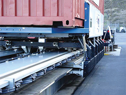
Fig. 8.25. (see color insert.) Prototype of urban maglev vehicle built by General Atomics, San Diego, CA, USA. Photo taken by the first author.
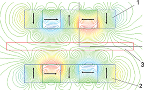
Fig. 8.26. PM configuration in General Atomics’ maglev vehicle. 1 — upper Halbach array, 2 — lower Halbach array, 3 — copper coils.

Fig. 8.27. Construction of active guideway of General Atomics’ maglev vehicle: (a) “ladder guideway”, (b) laminated guideway. 1 — Litz wire cable (rung of “ladder”), 2 — Cable ends soldered into shorting bus bars, 3 — copper or anodized aluminum sheets [171].

Fig. 8.28. (see color insert.) Principle of operation of General Atomics’ maglev vehicle. 1 — upper Halbach array levitation magnets, 2 — lower Halbach array levitation magnets, 3 — Litz wire guideway, 4 — LSM armature winding, 5 — propulsion magnets. Photo taken by the first author.
PM cofiguration comprises a pair of Halbach array magnetically and structurally connected together [P111, P118]. The levitation winding is located between the pair of Halbach arrays. The upper and lower arrays of PMs are phased with respect to each other so that their vertical field components add, while their horizontal field components cancel (or nearly cancel) in the gap between the two arrays as shown in Fig. 8.26. The guideway is made of Litz wire shorted coils. A “ladder guideway” with close-packed rungs can be constructed using Litz wire cables encapsulated in thin-wall stainless steel tubes [171]. The use of “braided” Litz wire assures current uniformity in the cables and minimizes eddy-current losses (Fig. 8.27a). A laminated copper or aluminum guideway has also been considered (Fig. 8.27b). The laminated guideway is a high-efficiency alternative to the Litz wire “ladder guideway.”
Halbach arrays of PMs have been configured to provide a nominal air gap of 25 mm. Upper levitation magnets and currents induced in short-circuited coils installed in the guideway produce attraction forces, while lower levitation magnets and currents induced in coils produce repulsive forces. As long as the vehicle keeps moving, these forces keep it airborne. When the vehicle slows down or comes to a stop, it settles back down onto its wheels, which are permanently deployed.
The thrust is provided by propulsion PMs (on the vehicle) that interact with the armature winding of a long laminated core LSM embedded in the guideway. Owing to large air gap, an LSM is fundamentally better suited to the needs of an EDS suspension system than an LIM. The LSM three-phase armature winding is simply made of copper cables. Levitation and propulsion components are shown in Fig. 8.28.
The lift Fz to drag Fx ratio as a function of the guideway circuit parameters is [170, 171]
where f = v/la, v is the linear velocity, la is the spatial period (wavelength) of Halbach array (from one pole to the next the same polarity pole), R and L are the guideway circuit resistance and inductance, respectively. The lift-to-drag ratio increases linearly with the velocity v and with the l/R ratio of the guideway circuit. Putting the output power Pout according to eqn (1.2) to eqn (8.9), the so-called levitation efficiency is
According to [171], typical value of ηl = 1 to 5, depending on the guideway design and arrangement of Halbach arrays.
The mass of empty vehicle is 9500 kg. The length of the vehicle is 12 m (two chassis units), the width is 2.6 m and the height is 3 m. The vehicle is supported on wheels when stationary, but levitates as it reaches the lift-off speed of about 2.5 m/s.
Testing with chassis weight up to 10,000 kg, to a speed of 10 m/s, air gaps up to 30 mm and acceleration up to 2.8 m/s2 have been achieved [74]. Upon successful completion of tests, the test track will continue being used for system optimization, while a demonstration system is constructed at California University of Pennsylvania (CalU) in California, PA, located about 60 miles southwest of Pittsburgh. When completed, this system will be 7.4 km in length with four stations and 3 vehicles, connecting the upper and lower campus via a 7% grade. The system will serve the main campus, the city, and student housing/sports facilities on the upper campus [74].
8.5 Swissmetro
Switzerland is a small country (41,293 km2) with a mountainous landscape and moderate density of population, i.e., 172 inhabitants per km2 (compare with 234.5 inhabitants per km2 in Germany and 333.3 inhabitants per km2 in Japan). The highest population density spread over a distance of 300 km is in the Swiss central plateau with major cities Geneva, Lausanne, Bern, Luzern, Zürich, St Gallen (West to East), and Basel and Bellinzona (North to South). The distance between each of the neighboring major cities is 40 to 100 km. There is a high saturation of main transport routes in Switzerland. To solve the transportation problems and protect the natural environment, a high-speed underground transportation network seems to be the only solution (Fig. 8.29).
8.5.1 Assumptions
The Swissmetro network project assumes speeds around 400 km/h, about 12 min travel time between stations, 3 min stops at stations, 4 to 8 trains per hour, and trains with minimum passenger capacity of 200 persons. The travel time from Zürich to Geneva will take less than 1 h as compared with 3 h by surface trains.
The Swissmetro project is based on four complementary modern technologies:
An underground infrastructure with two parallel tunnels of 5 m in diameter in each direction and stations linked to the existing public means of transportation (railways, roads, airports)
A partial vacuum with the air pressure reduced to 8 to 10 kPa (0.08 to 0.1 atm) in tunnels to minimize the air resistance and thus reduce the energy consumption
A propulsion system by using linear motors with guidaway mounted armatures
Support and guidance system by using the EML levitation technology
8.5.2 Pilot Project
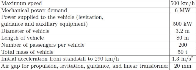
The line Geneva–Lausanne, about 60 km long, has been selected as the pilot project. The cross section of the tunnel and the vehicle is shown in Fig. 8.30. Specifications of the pilot vehicle are given in Table 8.7. To control the air gap of levitation and guidance electromagnets, air gap estimators based on determination of inductance will be used rather than position sensors.
Swissmetro vehicles require electric power for propulsion, guidance, and auxiliary equipment such as lights, airconditioning, communication, and safety equipment, which is estimated as 500 kW (power supplied to the vehicle, peak demand). The power will be transferred to the vehicle with the aid of high-frequency linear transformers. The long primary (about 1 km) of the linear transformer is fixed to the guidaway, and the secondary winding is fixed to the vehicle. At the frequency 2 kHz and air gap 20 mm, the predicted efficiency of the linear transformer is about 80%.

Fig. 8.29. (see color insert.) Cross section through the station of Swissmetro. Courtesy of Swissmetro, Geneva, Switzerland.
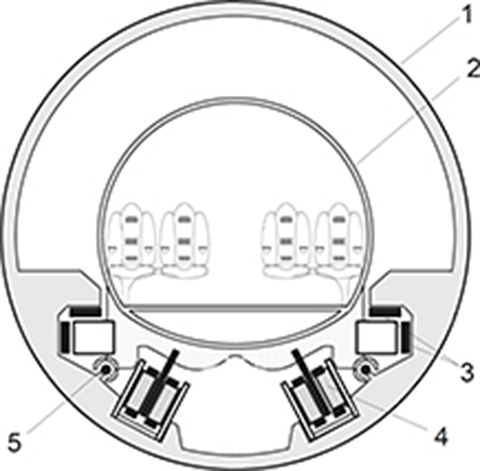
Fig. 8.30. Cross section of the tunnel and vehicle of Swissmetro pilot project: 1 — innner concrete tunnel ring (5 m diameter), 2 — passenger car body, 3 — EML levitation support and guidance system, 4 — LSM, 5 — linear transformer. Courtesy of Swissmetro, Geneva, Switzerland.
Table 8.7. Specification data of Swissmetro pilot vehicle. Courtesy of Swissmetro, Geneva, Switzerland
Two configurations of iron-cored LSMs have been investigated [181]:
guideway-mounted long armature with three phase winding and on-board excitation system;
guideway-mounted short three-phase armature integrated with excitation system and vehicle-mounted passive reaction rail.
Both configurations use two LSMs with pole pitch τ ≈ 0.323 m located in parallel at both sides of the guideway. LSMs are rated at 4.5 kV/1.4 kA or 6.4 kV/0.9 kA. The second configuration, i.e., double-sided homopolar LSM (Fig. 1.14, Chapter 1) seems to have more economical advantages. No electrical propulsion energy has to be delivered to the vehicle as three-phase armature windings are stationary, and the vehicle-mounted passive reaction rail needs neither windings nor PMs. The short armature sections about 10 m long are distributed along the tunnel in approximately 50 m intervals, equal to the length of the on-board passive reaction rail. The distance between armature sections should be shorter near and at the stations where trains require higher power for acceleration. Even if the armature sections are oversized due to the presence of the excitation system as compared with typical LSMs, there is a substantial saving on ferromagnetic materials and conductors. Both electromagnetic and PM field excitation of homopolar LSMs have been considered.
The power supply system distributing the electrical energy along the tunnel consists of 125/6.1 kV, 50 Hz transformers, and voltage source PWM converters with the output frequency 0 to 215 Hz. The following requirements are to be met by converters [181]:
maximum apparent power of 8.5 MVA at power factor cos ϕ = 0.85 (active power 7.225 MW);
power factor on the line side cos ϕ = 1.0;
operation in propulsion and regenerative braking mode with any desired power factor on the LSM side;
from 290 km/h up to maximum speed 500 km/h, the acceleration at constant electric power of 7 MW with efficiency exceeding 85%.
The maximum d.c. link voltage between rectifier and inverter has been assumed to be 10 kV.
The predicted energy consumption at constant speed of 400 km/h of the Swissmetro system, taking into account the maintenance of vacuum, is 43 Wh/(seat ×km). At the same speed, the Transrapid 07 consumes 50.4 Wh/seat ×km.
History of Swissmetro
1974 — Swiss engineer R. Nieth develops the concept of Swissmetro to provide high-speed transport between principal urban and rural areas.
1985 — Interest in the project is shown at a political level.
1989 — The Federal Department of Transport, Communication, and Energy (EVED) grants the Swiss Federal Institute of Technology (EPFL), Lausanne, a subsidy to conduct the preliminary study.
1992 — Founding of Swissmetro, S.A. in Geneva as a joint stock corporation.
1993 — The results of the preliminary study confirm the desirability, feasibility, and viability of the project. Inauguration of the first Swissmetro exhibition at Swiss Transport Museum in Lucerne.
1994 — Launch of the main study supported financially by major Swiss companies.
1998 — Main study of the system and components.
1999 — Swiss Government supports the project.
2000 — Study on the environmental impact of Swissmetro.
2009 — The Swissmetro SA in Geneva is going into liquidation because of lack of support. Around SFr 11 million ($10.77 million) was invested in the project, with federal authorities paying half. The rights were transferred to Federal Institute of Technology Lausanne (EPFL).
8.6 Marine Express
A reliable and weather-independent, short-distance inter-island or island-mainland link is still a difficult transportation and civil engineering task. Ferry connections are subject to the weather, and world statistics show numerous ferry sinkings with many casualties. Undersea tunnels are extremely expensive and demand expensive maintenance, e.g. to pump in fresh air and pump out the excessive water coming in all the time. For example, the world’s longest 53.85 km Seikan Tunnel between Honshu and Hokkaido islands (Japan), took over 40 years to be completed since its idea was conceived and geological survey began.
To combat noise, save land, and protect the natural environment, it is wise, where possible, to locate future airports on the sea, minimum 10 km away from the mainland. This can be done by building artificial islands. Such an airport requires reliable and convenient 24 hour passenger transportation between the mainland and artificial island. A similar problem arises in the case of future undersea cities accommodating hundreds thousands of inhabitants.
Amphibious trains traveling both under the water and on the dry land would be an ideal solution [244]. Such an underwater train, also called marine express, is proposed to be levitated on an elevated guidaway and propelled by linear motors [244]. The elevated guidaway can be laid on the sea bottom or on land. To overcome the buoyancy of the train under the water the bogie needs to be electromagnetically attracted to the guidaway. On land, the train needs to be levitated by repulsive forces. In both cases, a constant air gap is to be maintained by controlling the input electrical variables. An LSM with SC excitation system has been identified as the best candidate due to its high thrust, large air gap, low excitation power, and controllability of vehicle buoyancy under water [244].
Water density is much higher than that of air, and consequently, water resistance force is much higher than air resistance force — see eqn (1.55). It has been found that, in order to keep the same thrust, a 100 m long marine express traveling on land with the speed of 420 km/h will have to reduce its speed to 61 km/h under water [244]. On the other hand, the power required to run on land is 9.3 MW at 420 km/h in comparison with only 1.4 MW at 62 km/h under water (the power is approximately proportional to v3) [245].
A research team lead by K. Yoshida and T. Ota at Kyushu University, Fukuoka, Japan, has successfully tested small-scale prototypes of underwater train cars to prove the feasibility of the idea. An SC LSM has been replaced by a PM LSM [245]. When the buoyancy of the water is larger than the weight of the vehicle, an attractive-mode levitation and propulsion is realized by controlling the armature current and load angle.
A pitching-damping control method has been proposed to obtain stable levitation and propulsion. It is impossible to control the pitching angle completely together with the control of levitation and propulsion by controlling only the thrust Fx and normal force Fz [245]. On the other hand, by controlling the thrust Fx of an LSM, the pitching motion can be easily and effectively damped. The decoupled control of levitation and propulsion with pitching motion control is effective, and it has enabled a small-scale prototype vehicle to run successfully under water in a repulsive mode [245].
Examples
Example 8.1
Find the attraction force of a U-shaped electromagnet with the following dimensions: width of pole a = 12mm, length of core l = 200mm, length of the path of the magnetic flux in the ferromagnetic core including armature lF e = 400mm, nominal air gap g = 20mm. The total number of turns is N = 200, and the d.c. current in the coil is I = 100 A. Find the attraction force: (a) neglecting the magnetic voltage drop in the ferromagnetic core, and (b) including the magnetic voltage drop in the ferromagnetic core. The relative magnetic permeability of the ferromagnetic core is μr ≈ 200.
Solution
It can be assumed that the cross-section area of the ferromagnetic core is equal to the cross section of the air gap A, i.e.,
The attraction force, neglecting the magnetic flux path in the ferromagnetic core, is calculated using eqn (1.15), i.e.,
Including the magnetic voltage drop in the ferromagnetic core, the attraction force according to eqn (8.3) is
The corresponding magnetic flux density in the air gap
Table 8.8. Calculation results of attraction forces and corresponding magnetic flux densities for constant current I = 100 A and air gap range 8 ≤ g ≤ 30 mm. Example 8.1

Table 8.8 shows attraction forces and corresponding magnetic flux densities for constant current I = 100 A and air gap range 8 ≤ g ≤ 30 mm.
Example 8.2
A coil as shown in Fig. 8.2 with dimensions a = 1.0 m, l = 0.6 m, number of turns N = 200 carrying d.c. current I = 1000 A is moving with linear speed v = 20 m/s over a conductive aluminum plate with thickness d = 25.4 mm and electric conductivity σ = 30 × 106 S/m. The distance between the coil and conductive plate is g = 100 mm. Find the repulsive force between the coil and aluminum plate.
Solution
Assuming λ ≈ a, the frequency of the current in the conductive plate is f = v/λ = 20/1.0 = 20 Hz, and the angular frequency is ω = 2πf = 2π ×20 = 125.7 rad/s. The equivalent depth of penetration according to eqn (8.7)

Fig. 8.31. Repulsive force Fz and drag (braking) force Fx plotted against the linear velocity v of the coil carrying constant d.c. current I = 1000 A over aluminum plate (d = 25.4 mm, g = 100 mm). Example 8.2.
as given by eqn (8.6). Putting
and
the repulsive force, as calculated with the aid of eqn (8.4), is
Similarly, on the basis of eqn (8.8) the drag force is
The repulsive and drag forces are plotted against the linear velocity from v = 0 to v = 80 m/s in Fig. 8.31.
Example 8.3
The MLX01 three-car maglev trainset with an SC LSM runs on a practically horizontal guidaway with the specific gradient resistance kg = 0. The mass of the loaded train is m = 84 t, the front car is w = 2.9 m wide, and h = 3.28 m high with a wedge-shaped front nose. The following experimental test results on the Yamanashi Maglev Test Line are available [114]: (1) LSM propulsion force 200 kN at v = 350 km/h, and (2) acceleration a = 0.2g. Assuming air density ρ = 1.21 kg/m3 at 200C and 1 atm, find the required output power and specific “rolling” resistance for the MLX01 maglev train.
Solution
The weight of the trainset
The required output power of the LSM at constant speed v = 350 km/h is
For a wedge-shaped nose, the coefficient of proportionality in the air resistance force equation (1.55) is C ≈ 0.2. The air resistance force at v = 350 km/h
The air resistance force obtained from eqn (1.55) seems to be too small because the air resistance due to the longitudinal surfaces of the train has not been taken into account. Also, the air resistance due to tunnels has been neglected. The air resistance for MLX01 maglev train will probably be similar to that estimated for Transrapid maglev train, i.e., about 35 kN.
The specific acceleration resistance
On the basis of the traction effort equation (1.51)
This is rather a very rough estimation of kr. This resistance corresponds to the “rolling” resistance of wheel-on-rail trains and is due to braking forces of electrodynamic nature, i.e., interaction of the magnetic field of on-board SC electromagnets and induced currents in levitation and guidance coils.
1April 3, 2007, Eastern France, TGV with 18.65-MW total power of electric motors and three double-decker cars.