
Appendix A
Magnetic Circuits with Permanent Magnets
A.1 Approximation of Demagnetization Curve and Recoil Line
The most widely used approximation of the demagnetization curve is the approximation using a hyperbola, i.e.,
where B and H are coordinates, and a0 is the constant coefficient that can be evaluated as [19]
or
where (Bi, Hi) are coordinates of points i = 1, 2, … n, on the demagnetization curve, arbitrarily chosen, and n is the number of points on the demagnetization curve.
The recoil magnetic permeability is assumed to be constant and equal to [19]
The above equations give a good accuracy between calculated and measured demagnetization curves for Alnicos and isotropic ferrites with low magnetic energy. Application to anisotropic ferrites with high coercivity can in some cases cause errors.
For rare-earth PMs, the approximation is simple due to their practically linear demagnetization curves, i.e.,
This means that putting a0 = 0 or γ = 0.25, eqn (A.1) gets the form of eqn (A.5).
A.2 Operating Diagram
A.2.1 Construction of the Operating Diagram
The energy of a PM in the external space only exists if the reluctance of the external magnetic circuit is higher than zero. If a previously magnetized PM is placed inside a closed ideal ferromagnetic circuit, i.e., toroid, this PM does not show any magnetic properties in the external space in spite of the fact that there is magnetic flux Φr corresponding to the remanent flux density Br inside the PM.
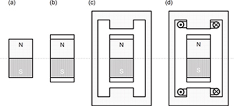
Fig. a.1 Stabilization of a PM: (a) PM alone, (b) PM with pole shoes, (c) PM inside an external magnetic circuit, (d) PM with a complete external armature system.
A PM previously magnetized and placed alone in an open space, as in Fig. A.1a, generates a magnetic field. To sustain a magnetic flux in the external open space, an MMF developed by the magnet is necessary. The state of the PM is characterized by the point K on the demagnetization curve (Fig. A.2). The location of the point K is at the intersection of the demagnetization curve with a straight line representing the permeance of the external magnetic circuit (open space), i.e.,
The permeance Gext corresponds to a flux Φ–MMF coordinate system and is referred to as MMF at the ends of the PM. The magnetic energy per unit produced by the PM in the external space is wK = BKHK/2. This energy is proportional to the rectangle limited by the coordinate system and lines perpendicular to the Φ and coordinates projected from the point K. It is obvious that the maximum magnetic energy is for BK = Bmax and HK = Hmax.
If the poles are furnished with pole shoes (Fig. A.1b), the permeance of the external space increases. The point that characterizes a new state of the PM in Fig. A.2 moves along the recoil line from the point K to the point A. The recoil line KGM is the same as the internal permeance of the PM, i.e.,
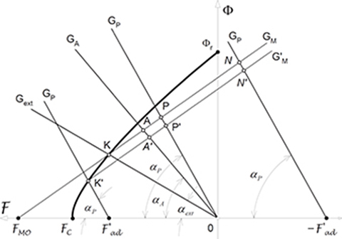
Fig. a.2 Diagram of a PM for finding the origin of the recoil line and operating point.
The point A is the intersection of the recoil line KGM and the straight line OGA representing the leakage permeance of the PM with pole shoes, i.e.,
The energy produced by the PM in the external space decreases as compared with the previous case, i.e., wA = BAHA/2.
The next stage is to place the PM in an external ferromagnetic circuit as shown in Fig. A.1c. The resultant permeance of this system is
which meets the condition GP > GA > Gext. For an external magnetic circuit without any electric circuit carrying the armature current, the magnetic state of the PM is characterized by the point P (Fig. A.2), i.e., the intersection of the recoil line KGM and the permeance line OGP.
When the external magnetic circuit is furnished with an armature winding and when this winding is fed with a current that produces an MMF magnetizing the PM (Fig. A.1d), the magnetic flux in the PM increases to the value ΦN. The d-axis MMF of the external (armature) field acting directly on the PM corresponds to ΦN. The magnetic state of the PM is described by the point N located on the recoil line on the right-hand side of the origin of the coordinate system. To obtain this point, it is necessary to lay off the distance and to draw a line GP from the point inclined by the angle αP to the -axis. The intersection of the recoil line and the permeance line GP gives the point N. If the exciting current in the external armature winding is increased further, the point N will move further along the recoil line to the right, up to the saturation of the PM.
When the excitation current is reversed, the external armature magnetic field will demagnetize the PM. For this case, it is necessary to lay off the distance from the origin of the coordinate system to the left (Fig. A.2). The line GP drawn from the point with the slope αP intersects the demagnetization curve at the point K′. This point can be up or down of the point K (for the PM alone in the open space). The point K′ is the origin of a new recoil line K′G′M. Now, if the armature-exciting current decreases, the operating point will move along the new recoil line K′G′M to the right. If the armature current drops down to zero, the operating point takes the position P′ (intersection of the new recoil line K′G′M with the permeance line GP drawn from the origin of the coordinate system).
On the basis of Fig. A.2, the energies wP′ = BP′HP′/2, wP = BPHP/2, and wP′ < wP. The location of the origin of the recoil line as well as the location of the operating point determine the level of utilization of the energy produced by the PM. A PM behaves in a different way than a d.c. electromagnet: the energy of a PM is not constant if the permeance and exciting current of the external armature changes.
The location of the origin of the recoil line is determined by the minimum value of the permeance of the external armature or the demagnetization action of the external field.
To improve the properties of PMs independent of the external fields, PMs are stabilized. In magnetic circuits with stabilized PMs, the operating point describing the state of the PM is located on the recoil line. Stabilization means the PM is demagnetized up to a value that is slightly higher than the most dangerous demagnetization field during the operation of a system where the PM is installed.
A.2.2 Magnetization without Armature
In most practical applications, the PM is magnetized without the armature and is then placed in the armature system with an air gap. In Fig. A.3 the demagnetization curve is plotted in flux Φ–MMF coordinate system. The origin of the recoil line is determined by the leakage permeance Gext of the PM alone located in open space (Fig. A.3).

Fig. A.3 Location of the operating point for magnetization without the armature.
For rare-earth PMs, the recoil permeability μrec and the equation of the recoil line is the same as that for the demagnetization line.
The armature field usually demagnetizes the PM so that the line of the resultant magnetic permeance, Gt, intersects the recoil line between the point K and the magnetic flux axis.
The magnetic flux in the PM is . Using the coefficient of leakage flux (2.14), the useful flux density in the air gap can be found as [70]
where Sg is the surface of the air gap. With the fringing effect being neglected, the corresponding magnetic field intensity is
In the general case, the resultant permeance Gt of the external magnetic circuit consists of the useful permeance Gg of the air gap and the leakage permeance GlM of the PM, i.e.,
The useful permeance Gg corresponds to the useful flux in the active portion of the magnetic circuit. The leakage permeance GlM is the referred leakage permeance of a single PM or PM with armature. Consequently, the external energy wext can be divided into useful energy wg and leakage energy wlM. The useful energy per volume in the external space is
A.2.3 Magnetization with Armature
If the magnet is placed in the external armature circuit and then magnetized by the armature field or magnetized in a magnetizer and then the poles of the magnetizer are in a continuous way replaced by the poles of the armature, the origin K of the recoil line is determined by the resultant magnetic permeance Gt drawn from the point at the -coordinate. The MMF corresponds to the maximum demagnetizing d-axis field acting directly on the magnet that can appear during the machine operation. In Fig. A.4, this is the intersection point K of the demagnetization curve and the line Gt:
The maximum armature demagnetizing MMF F′admax can be determined for the reversal or locked-rotor condition.
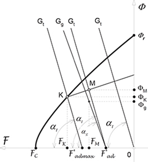
Fig. A.4 Location of the operating point for magnetization with the armature.
The origin of the recoil line is determined by the resultant permeance Gt of the PM mounted in the armature (Fig. A.4).
The rest of the construction is similar to that shown in Fig. A.3 for the demagnetization action of the armature winding (point M). The beginning of the recoil line is determined by the resultant permeance Gt of the PM mounted in the armature (Fig. A.4).
If a0 > 0, the MMF corresponding to the point K is [70]:
where
If a0 = 0 (for rare-earth PMs), the MMF is [70]:
The magnetic flux ΦK can be found on the basis of eqn (A.14).
The rest of the construction is similar to that shown in Fig. A.3 for the demagnetization action of the armature winding (point M).
A.2.4 Equivalent Magnetic Circuit
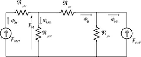
Fig. A.5 Equivalent circuit (in the d-axis) of a PM system with armature.
The equivalent magnetic circuit of a PM system with armature is shown in Fig. A.5. The reluctances of pole shoes (mild steel) and armature stack (electrotechnical laminated steel) are much smaller than those of the air gap and PM and have been neglected. The “open circuit” MMF acting along the internal magnet permeance GM = 1/ℜμM is , the d-axis armature reaction MMF is , the total magnetic flux of the permanent magnet is ΦM, the leakage flux of the PM is ΦlM, the useful air gap magnetic flux is Φg, the leakage flux of the external armature system is Φla, the flux produced by the armature is Φad (demagnetizing or magnetizing), the reluctance for the PM leakage flux is ℜμlM = 1/GlM, the ai rgap reluctance is ℜμg = 1/Gg, and the external armature leakage reactance is ℜμla = 1/Ggla. The following Kirch-hoff’s equations can be written on the basis of the equivalent circuit shown in Fig. A.5
The solution to the above equation system gives the air gap magnetic flux:
or
where the total resultant permeance Gt for the flux of the PM is according to eqn (A.12) and the direct-axis armature MMF acting directly on the PM is
The upper sign in eqn (A.17) is for the demagnetizing armature flux and the lower sign is for the magnetizing armature flux.
The coefficient of the PM leakage flux can also be expressed in terms of permeances, i.e.,