9
Building and Factory Transportation Systems
9.1 Elevator Hoisting Machines
Hoisting technology started when Archimedes constructed the first elevator that was based on pulleys and winches around 236 BC. However, early primitive elevators did not guarantee any safety for passengers. The situation changed with E. Otis’ invention of a reliable safety gear in 1853 [P1]. In the first elevators, the drum was used to collect the rope. The major disadvantage was the necessity to lift the load together with the supporting structure. The next type, referred to as a rope traction elevator, has been constructed in such a way as to obtain the load balanced by the counterweight. This latter construction is widely used today.
Elevators can be classified into three major categories based on their size:
High-rise elevators used in the tallest buildings in major cities and manufactured at a volume of about 2,000 units annually. These elevators add image and prestige to the company manufacturing them.
Mid-rise elevators installed in office buildings, hotels, and other similar structures (annual market size of approximately 20,000 units). The appearance, comfort, and ride quality become most important for these installations.
Low-rise elevators mostly installed in residential buildings (total annual sales of about 200,000 units worldwide).
There is an increasing demand to reduce both the space needed for hoistways in buildings and the size of elevator electrical supplies. These requirements have a strong influence on the selection of the hoisting machine, which can be remarkably improved by utilizing a linear motor [78]. Because the linear motor produces straightforward movement without mechanical transformations, thus improving the efficiency due to a smaller number of components, the usage of linear motors appears highly attractive. This technology matured in 1991 when Nippon Otis introduced the first commercial application of the linear motor elevator into the Japanese market [202]. Since then, the intensive research in this field was aimed at surpassing conventional technology in performance and cost. The type of electric motor, i.e., induction, switched reluctance, or synchronous, is important in the linear motor elevator technology. However, the elevator structure is even more important because requirements for the hoisting system vary with the arrangements of the elevator components. Sometimes the hoisting machinery must lift all traveling masses, whereas in other cases the counterweight, does part of the work. Moreover, in some elevators, the weight of the motor can be utilized as part of the mass balance.
9.1.1 Linear-Motor-Driven Elevator Cars
The earliest patent concerning a linear motor in elevators was granted to K. Kudermann in 1970 [P211]. The principle of that patent is illustrated in Fig. 9.1. The proposed system consists of a counterweight and two linear motor armatures on both sides of the car. The disadvantage of this setup is that the motor must also lift its own weight, thus increasing the demand for power supply during acceleration.

Fig. 9.1. Armature of a linear motor installed in the elevator car.
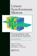
The best linear motor drive is a combination of the double-sided motor with the guide rail, which provides an advantage in balancing the attractive forces. The linear motor must be distributed on both sides of the car to obtain a symmetrical hoisting. The analysis of a few types of motors indicates that the LSM with ferrite PMs can offer the smallest cost-related mass, as shown in Table 9.1 [78]. The relative power used in Table 9.1 is defined as
where Phoist = mlgv is the hoisting power, v is the rated speed at rated load of the elevator, Pinm is the power supplied by the hoisting machinery, and ΔP is the power dissipated in the hoisting system. The relative power loss is the ratio of losses to the hoisting power
The Phoist is not a theoretical minimum for the power of the hoisting machine because the counterweight does a part of the hoisting work, and the rest must by supplied by the hoisting machinery.
Table 9.1. Comparison of different linear motors applied in 1000 kg car traveling at 2 m/s for mid-rise elevator. Cost of related motor masses reflects material cost in 2010
The relative masses are moving masses or stationary masses related to the mass of the rated load of the elevator ml.
The relative drive size is defined as the ratio of the maximum electrical current demand Imax to the current corresponding to the hoisting power Ihoist.
The relative cost represents the weighted prices of the active material used for the elevator, excluding all the supportive structures and scaled to the mass of the whole hoisting system. The cost weighting coefficients have been assumed as follows: 2 for steel, 5 for aluminum, 8 for copper, 4 for ferrite PMs, and 40 for NdFeB PMs.
Coefficients listed in Table 9.1 lead to the conclusion that the PM LSM can offer the smallest cost-related mass, thus being the most promising alternative. On the other hand, it still remains uncertain whether the benefit of eliminating the rotary machine can be favorably compared to the increased cost of the linear motor.
9.1.2 Elevator with Linear Motor in the Pit
The alternative for a hydraulic elevator can be a linear motor with moving reaction rail as shown in Fig. 9.2.

Fig. 9.2. Linear-motor-driven elevator with moving reaction rail.
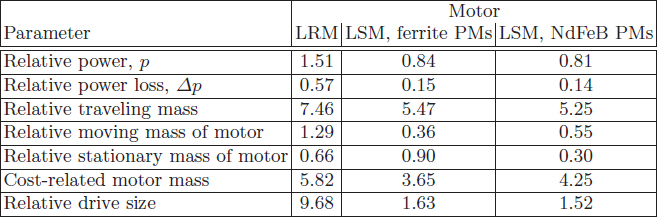
The idea is to replace the piston of hydraulic machinery with the reaction rail, and the cylinder with the armature of the linear motor. Power can be supplied to the stationary winding. However, either a pit in the basement or the 1:2 roping ratio is required to obtain the required doubled force. Furthermore, the car travel distance is limited to maximum 20 m. Comparison of different linear motors installed in the pit for low-rise elevators is given in Table 9.2.
The structure has the same features as the hydraulic set-up but with a few additional advantages, i.e.,
no oil and oil tank,
all machinery is located in the shaft, so that a separate room is not needed,
the regenerative braking can be applied for the car going downward, so that the lack of counterweight can be partially compensated.
The performance of this elevator with PM LSM compares well with the conventional hydraulic system, but the amount of magnetic material required makes this structure commercially unattainable.
Table 9.2. Comparison of different linear motors installed in the pit for low-rise ropeless elevator (1600 kg car, 4 m/s). Cost of related motor masses reflects material cost in 2010 [78]
9.1.3 Linear Motor in Counterweight
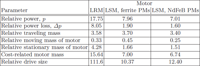
The counterweight is the most natural place for the linear motor in a traction type elevator. In this way, the mass of the motor can be utilized as a part of the balance. However, the energy must be supplied to the motor through a cable, the length of which on the balance side varies with the counterweight position. Proper measures should then be taken to compensate for this variation of the balance weight. This counterbalance motor placement has been well known for some time and even commercially explored [P14, P50, 202]. Although, similar to the motor installation in the car, when the motor is installed in the counterbalance, the difference in the mass of the supply cable must be taken into account (Fig. 9.3a).
The mass of the counterweight for optimum balancing should be
and the mass of balancing ropes (per unit length)
where mc is the mass of the counterweight, m is the mass of the car, ml is the mass of the rated load, mec is the mass per unit length (kg/m) of the traveling electric cable on the counterweight side, me is the mass per unit (kg/m) of the traveling electric cable on the car side, mrope is the mass of rope per unit length (kg/m), and H is the total hoisting height. The possible linear motor placement in the counterweight is shown in Fig. 9.3b. The system can be designed with the armature in the counterweight and reaction rail on the wall, as well as with the reaction rail in the moving counterweight and the armature on the wall.
Fig. 9.3. Elevator system with the linear motor in the counterweight: (a) construction, (b) possible location of the linear motor.
Table 9.3 shows a comparison of different linear motors mounted in the counterweight of a low-rise elevator. PM LSMs require less power than conventional hoisting motors. Further analysis shows that the performance of a reluctance motor improves at higher speeds.
9.1.4 Conventional versus Linear-Motor-Driven Elevator
Table 9.4 illustrates the major parameters of a mid-rise elevator system with different motor types [78]. Both the conventional traction motor and linear motor placed either in the car or in the counterweight offer approximately the same sizing of a hoisting machinery and the drive.
Table 9.3. Comparison of different linear motors mounted in the counterweight of a low-rise elevator (630 kg car, 1 m/s). Cost of related motor masses reflects material cost in 2010 [78]

Table 9.4. Rotary motors versus linear motors for mid-rise elevators (1000 kg car, 2 m/s). Cost of related motor masses reflects material cost in 2010

9.2 Ropeless Elevators
9.2.1 Vertical Transport in Ultrahigh Buildings
Land in the world’s biggest cities, e.g., New York or Tokyo, is extremely expensive, which drives the expansion of rentable spaces into higher and higher buildings and underground areas. However, the larger and taller the buildings, the more elevators are required to keep acceptable waiting time for dispatching. The increasing interest in ultrahigh buildings, also called hyper buildings or vertical cities that exceed 600 m in their height inspires elevator companies to intensify their research effort in alternative technologies for vertical transportation. This becomes apparent in Japan where building contractors, elevator companies, and other institutions are spending considerable effort in developing transportation concepts for these hyper buildings. Vertical transportation systems in ultrahigh buildings must address many technical issues, amongst others
transport configuration with traffic flow within and between buildings;
diverse building capacity incorporating residential, commercial, and service functions;
use of alternative building transportation systems (roped elevators, ropeless elevators, escalators, people movers);
the highest levels of reliability, safety, and passenger rescue;
comfort of travel (air pressure changes, vibration, vertical and horizontal motions, travel time);
elevator propulsion, guidance, brakes, power consumption, control, and communication.
Ultrahigh buildings pose new problems in the construction of high-speed elevator systems, i.e., vertical oscillations, horizontal swing, car noise, and cable length limitations. Because the ropes (steel cables supporting the car) are very long and usually have a low dumping coefficient, even small disturbances, e.g., traction machine torque ripple, can cause car oscillations. This vibration can further be amplified when the disturbance frequency coincides with the car’s natural frequency. In some instances, this bounce may destabilize the system that controls the elevator speed. The horizontal swing of the elevator car can be caused by curvatures of the guiding rails or by imperfect rail segment junctions. Car noise is due to the roller-guides tracking the rails and by wind noise (air passing through the traveling car).
The car rise limit is imposed by the cable weight and strength and can be considered as a function of five variables: (a) safety factor, (b) rope strength, (c) rope mass per unit length, (d) number of ropes, and (e) mass of the car. Under the most favorable conditions, a cable-based elevator can achieve a rise of approximately 1200 m, based on 10 commonly used steel cables with 320 kN strength, mass per unit length of 2.14 kg/m, and safety factor of 10 [95].
Ropeless elevators with multiple cars in one shaft may be perceived as practical solution to ultratall buildings above 1000 m. The primary concern is that the roping technology may not be extensible to hoistways of that height, both from a rope strength standpoint, and safety margin considerations. Another problem is that roped elevator systems, understood to be based on sky lobbies, would consume too much space to make such a building financially viable. An analysis conducted by Mitsubishi Corporation [95] found that almost 30% of the total space in a 100-floor skyscraper must be devoted to elevators, including their hoistways, halls, and machine rooms (Fig. 9.4). Recently, the peak rents for Tokyo skyscrapers were estimated about US$ 1000/m2/year. Clearly, the elevator space occupancy ratio has a significant financial impact on building utilization.
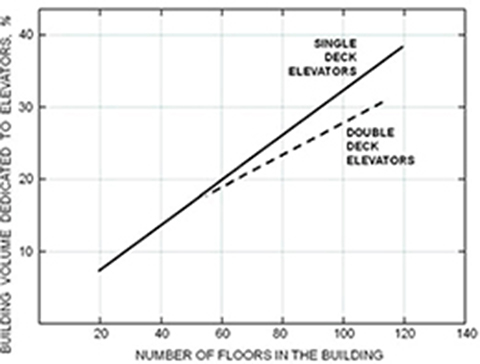
Fig. 9.4. Elevator system space occupancy ratio in a tall building.
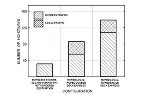
Fig. 9.5. Required number of hoistways in roped and ropeless elevator system capable dispatching 2000 passengers per minute. Study for 250-floor building, 1000 m tall, with 100,000 population.
The one-shaft, multicar, ropeless elevator system is considered to be the most promising answer to these problems. It eliminates the suspension cables, and with them, the rope-strength and vertical-oscillation problems. Use of multiple cars in a single hoistway improves the space occupancy factor even when compared with roped double-deck elevators. For example, the required number of hoistways can be reduced by 65% to 80% when using a ropeless elevator with multiple cars versus traditional roped system (Fig. 9.5).
The mining industry is also interested in alternative vertical transportation systems with ropeless elevators [43]. South African ultra-deep gold mines (exceeding 3500 m) are considering the implementation of PM-LSM-driven hoisting systems because the maximum depth achievable by a roped hoist system is approximately 2800 m. After this depth, the hoisting rope can no longer support its own weight and the payload. To overcome this problem, at the present time, subvertical shafts are sunk, i.e., additional roped hoist system are installed underground at a depth of about 2000 m [43].
9.2.2 Assessment of Hoist Performance
The hoist efficiency without the rope is independent of the height (in a mine independent of the depth), and therefore, the operation of the lifting machinery is not limited by the rope mass.
The successful implementation of the linear motor hoist depends on two main factors: (a) the ratio of the motor weight–to–thrust that it can produce, and (b) the motor size (cost).
One of the main criterion for assessing the performance of the hoist is the efficiency of the overall system [44]:
where Poutm is the mechanical power required to lift the payload, Pinm is the total mechanical power required to operate the system, ml is the mass of the payload, m is the mass of the car, mrope is the mass of ropes, g is the acceleration of gravity, and v is the linear speed.
Assuming a constant speed of operation and neglecting the friction, the efficiency of the hoist system without a counterweight can be expressed as follows [44]:
for a conventional roped hoist
for a ropeless hoist
Assuming that the mass of the car and payload are the same in both cases, the system efficiency becomes entirely dependent on the mass of ropes.

Fig. 9.6. Limits of rope lift system imposed by cable mass: (a) comparison of hoisting system efficiencies, (b) rope ability to support its own weight.
The taller (deeper) the hoist shaft, the longer and therefore the heavier the rope since where ρ is the specific mass density of steel and nrope, drope, and lrope are the number of ropes, diameter, and length of the rope, respectively. Heavier ropes have larger diameter to withstand the increased tensile stresses. As a result, the increased cross-sectional area of ropes contributes further to their mass, affecting the overall system efficiency (Fig. 9.6a) [43].
The efficiency of roped hoist without counterweight tends to zero as the height (or depth) approaches the operating limit (about 2800 m for steel ropes).
Technologies crucial to the successful development of ropeless elevators can be divided into four major categories:

Fig. 9.7. One shaft, multicar, ropeless elevator with two long armature LSMs.
system configuration and energy management
propulsion and guidance
safety and brakes
control and communication
9.2.3 Construction of Ropeless Elevators
The unique features of the ropeless elevator include
unlimited rise,
vertical and horizontal motion,
multiple cars in the same hoistway,
no traveling cable,
high traffic-handling capacity with minimum core space.
The ropeless elevator with multiple cars in one shaft can be built by hanging each cab from a bar fixed to the movers of a pair of LSMs (Fig. 9.7). Long armature windings are stationary, and PMs are integrated with movers. Each car hangs from a shaft fixed to the PM movers. The mover is a steel rail with PMs that is installed between two parallel stationary armature systems. Armature units are segmented into blocks (Fig. 9.8). The guidance system maintains a small and constant air gap between the armature cores and PMs. When the armature windings are excited, the interaction between the excitation flux and the flux of PMs produces linear thrust moving the car up or down. The long stationary armature is divided into sections, the minimum number of which is equal to the number of cars. Only one car can be permitted in each section at a time so that each car may be controlled independently of the others. The more sections there are, the more precisely the system can be controlled; however, the construction cost is higher since each section requires its own high-power converters.

Fig. 9.8. Ropeless elevator with double-sided PM LSM.
9.2.4 Operation
The LSM-powered ropeless elevator consumes significantly more energy than an equivalent roped elevator to move a given number of passengers to a given distance. The reason for this is that a typical counterweighted elevator with ropes needs to drive only the offset load (typically only 12% to 14% of the total moving mass), while the ropeless elevator must lift the entire combined mass of the car, the frame, passengers, and the PM movers. Assuming motors and converters of similar efficiency, the ropeless elevator requires power supply 7 to 8 times that of its roped counterpart.
An ascending ropeless elevator requires almost constant power for a given load as it rises in the hoistway. When moving at constant speed, the power is consumed to overcome the force of gravity. Peak acceleration or deceleration, when limited to 0.11g increases or decreases the power required by only about 10%. During the descent, a significant portion of energy is recovered as the LSM is able to regenerate it from the passage of the PM excitation system through the armature windings. However, the recovered energy is always smaller than the propulsion energy because regeneration occurs when the descending car travels with speed exciting higher EMF in the winding than the drop voltage on the winding impedance. Fig. 9.9b shows that the car absorbs the power taken from the electric supply system as it starts traveling downward. A freely falling car would develop the acceleration equal to 1.0g, that is too high for the passengers riding inside. To limit the acceleration to 0.11g the LSMs must develop braking thrust (directed upward) slightly smaller than the gravitational force.
9.2.5 First Prototypes
Completing a study on very large drives in the early 1990s, the Underground Development Utilization Research Center of the Engineering Advancement Association of Japan (ENNA) is seriously considering the application of linear motors to ropeless elevators. This demonstrative research was conducted by a group of five companies: Fuji Electric, Ishikawajima–Harima Heavy Industries, Kawasaki Heavy Industries, Simizu Corporation, and Fujitec. ENNA has already built a working model of a horizontal and vertical ropeless transport system [121]. This scaled installation serves as a model for future hyper building transportation systems. Specifications are the following:
maximum thrust 3,000 N
vertical travel distance 8 m
horizontal travel distance 1 m
velocity from 0 to 1 m/s
acceleration 1 m/s2
moving mass 270 kg (including payload)
car dimensions: 1.0 W ×0.9 D ×1.8 H m
power and control: IGBT inverter
position encoder: optical pulse generator
The overall view of the test system is shown in Fig. 9.10. The car is suspended as a pendulum from the traveling carriage. To prevent the car from swaying at the time of acceleration or when passing through a curved rail, a friction plate has been set between the carriage structure and the car. The car is guided by two rails: (a) a rigid H-shaped beam, which supports and guides the car (travel rail), and (b) a motor guidance maintaining a constant linear motor air gap. The system is capable of moving the car both along the straight and curved path. Such a transition takes approximately 10 s.
To meet the most important propulsion system requirements, i.e., lightweight and large motive force, an LSM with PM mover installed on the car and the armature on the track has been adopted. The mover is placed between two sets of stationary armature systems. High-energy N32 NdFeB PMs (energy product 255 kJ/m3) have been used. PMs are fixed to both sides of 10 mm thick steel rails and skewed by one slot pitch of armature core to reduce the thrust ripple (Fig. 9.11a). To minimize the attractive forces between PMs and armature cores, a double-sided armature configuration has been chosen (Fig. 9.11). This motor topology is referred to as a U-type LSM with short PM reaction rail and two long armature systems.

Fig. 9.9. Computed motion profile for a car of ropeless elevator moving 16 passengers with 10 m/s of contract speed in the 1000 m rise hoistway: (a) for car going up, (b) for car going down.

Fig. 9.10. Linear-motor-driven vertical–horizontal transportation system built by Japanese ENNA consortium.

Fig. 9.11. Construction of PM LSM for ENNA ropeless elevator system: (a) PM mover, (b) double-sided armature. 1 — PM-mounting aluminum plate, 2 — locking bar, 3 — protective cover made of non-ferromagnetic stainless steel, 4 — steel plate, 5 — PM.
The armature of LSM is divided into 10 straight and curved sections, each about 2 m long. The segments are powered from sinusoidal IGBT inverters with low noise emission levels arranged in a tandem. The power from inverters is distributed by means of switches connecting individual armature sections in a sequence (Fig. 9.12). When the mover travels between the segments, both inverters operate; otherwise, only one is used. The presented system is able to fully control the movement of a single carriage. For higher number of cars, a more complicated power distribution scheme is needed. The speed and position are detected by a slotted plate on the car and photodetectors mounted on the track.

Fig. 9.12. Power distribution system.
The safety of the system is guaranteed by a braking device activated by a hydraulic system that is mounted at each end of the trace ends to hold the traveling carriage in position. Oil buffers are mounted to minimize a sudden impact in the case of an improperly decelerating carriage. An electrical dynamic braking is applied in the case of power failure to prevent a free fall of the car. The armature windings are automatically connected (shunted) to the external resistors. The power dissipated in the braking resistor provides smooth, controllable braking force, allowing the car to descend at stable crawl speed even when all safety monitoring equipment fail.
The ENNA project, completed in 1995, shows that, in the near future, the vertical transportation system would evolve into arteries in which cars could move three-dimensionally. Travel will not be limited to enclosed spaces, like the conventional elevator systems in use today, but multiple passenger cars will be moving freely between floors, buildings, in underground or in any subterranean space.
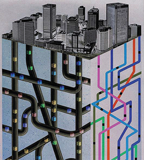
Fig. 9.13. Artist’s impression of vertical–horizontal transportation system in a future high-rise building district. Courtesy of Fuji Electric Holdings Co., Ltd., Tokyo, Japan.
Fig. 9.13 shows an artist’s impression of a future high-rise building district with vertical–horizontal ropeless elevators propelled by linear motors.
9.2.6 Brakes
One of the most important elevator subcomponents is a braking system. The brake must:
maintain the car in a fixed vertical and horizontal (side-to-side and front-to-back) position while passengers are boarding and exiting;
operate to stop the vertical motion of the car under complete power failure;
have the capability of producing at least 1.0 m/s2 deceleration for periods above 10 s when the car is traveling downward;
supply auxiliary guidance to the car in the case of a complete power failure. This requirement is important for elevators with active magnetic guidance (AMG) [156].

Fig. 9.14. Ropeless elevator brakes: (a) installation, (b) commercial brake caliper type from Nexen, Vadnais Heights, MN, USA (formerly Horton Industrial Products).
The primary function of a brake is to hold the car in a fixed position when passengers are entering and exiting. While this function could be accomplished using an electric motor, it is more efficient to use a friction brake to hold the car in position. In a roped elevator, this brake generally acts on a drum attached to the sheave. Therefore, a releveling process is required as the car load changes and the cable length between the brake and the car stretches or contracts. For the brake mounted directly on the car (ropeless design), the need for releveling is eliminated as there is no cable located between the brake and car stretch. The second function of the brake is to provide stopping the car in the case of a power failure. The braking force in a conventional elevator is generally applied by a spring pressure and released using an electrical actuator (solenoid). In the case of an electrical outage, the braking force is automatically produced by the spring pressure. Usually, elevator brakes are either fully applied or fully disengaged. Normally they would not be modulated or applied gently to generate, for example 50%, of possible braking force.
The brake in a standard roped elevator is used under steady-state conditions. It is applied after the car has completely stopped, and released only after the motor has been energized to support the car. This is done to prevent the car from lurching either up or down at the brake release. Conventional elevator brakes may also operate in a dynamic mode if power is lost to the hoistway or safety limits are exceeded. In this mode, the brake is required to stop the car safely while it is moving up to 120% of the contract speed, i.e., speed negotiated between the manufacturer and customer.
Brakes for ropeless elevators will have to meet more severe requirements. With ropeless elevators, it is possible to use a caliper friction brake, similar to the standard elevator brake. The caliper and brake assemblies should be attached to and move with the car. These brakes can be actuated by a spring and retracted by an electromagnetic actuator. There should be one brake assembly on each side of the car, acting against the same rails (T-rails) as safety devices. Under normal operation, the car comes to a stop being driven by the LSM, and the brake is only deployed after car has stopped. In case of emergency, the brake needs to be capable of stopping the moving car. An example of caliper brake installation on the ropeless elevator car is shown in Fig. 9.14.
9.3 Horizontal Transportation Systems
9.3.1 Guidelines for Installation
Linear motors can simplify the transfer bulk and loose materials, small containers, pallets, bottled liquids, parts, hand tools, documents, etc., in building and factory transportation systems. It is easy to adopt the linear motor system to the allowable space as linear motors are compact machines, do not have rotating parts, do not need maintenance and allow design of a transfer system that is in harmony with surrounding equipment. Linear motors are silent, and the noise emitted does not exceed 65 dB. Magnetic fields emitted by armature windings and PM excitation system are not dangerous to human organisms. Well-designed transportation systems emit very low level of RFI. High-intensity magnetic fields exist only in the air gap between the armature and reaction rail.
It is possible to design both on-floor and overhead transportation systems. Moreover, the linear motor transportation line can be sloped to create a link between two or more floors. Parallel transportation lines or line for double-deck carriages can also be designed. The rule is that transportation lines must never cross. If, say, a loop like “8” shaped line is needed, the crossing must be designed on two different levels. Possible designs are shown in Fig. 9.15 [106].
Stations for loading and unloading materials must be carefully planned, and additional space must be reserved. Linear motors cannot be installed near inlets and exhausts of air-conditioning systems because airborne dirty particles could deteriorate the sensors’ performance and sometimes contaminate the air gap between the armature and reaction rail. In the case of PM excitation, the space around the reaction rail must be free of any ferromagnetic particles.
9.3.2 Construction
There are two basic constructions of building or factory horizontal transportation systems with LSMs:
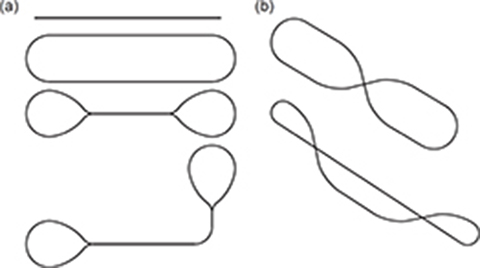
Fig. 9.15. Arrangement of linear motor transportation lines: (a) on one level, (b) on two levels.
Long stationary reaction rail with PMs and moving short armature (Fig. 9.16)
Stationary armature or armatures and moving reaction rail with PMs (Fig. 9.17) [184, 185]
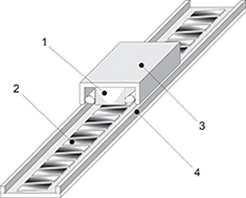
Fig. 9.16. Horizontal factory transportation system with moving short armature LSM and long PM reaction rail. 1 — armature, 2 — PMs, 3 — carrier, 4 — guiderail.
The stationary long reaction rail is expensive, and the moving armature winding needs a contactless energy transfer [201]. It is more economical to use stationary short armature units distributed along the track. The mover is accelerated by the short armature unit and is then driven by its own inertia. Since the speed decreases, the next unit must be installed at a certain distance to reaccelerate the mover (Fig. 9.18). The longer the travel distance, the more armature units need to be used. Such discontinuous arrangement of LSMs requires synchronization of the speed of the mover (PM reaction rail) and traveling magnetic field. The method of synchronization can use either feedback signals from position sensors or open-loop control of synchronization [184, 185]. The first methods are very reliable; however, they are costly. Open-loop methods are more economical (lower cost of sensors).
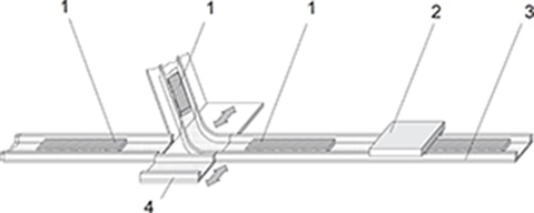
Fig. 9.17. LSM horizontal transportation system with stationary discontinuous armature and short moving PM reaction rail. 1 — armature unit, 2 — carrier with PM excitation system, 3 — guiderail, 4 — switch.
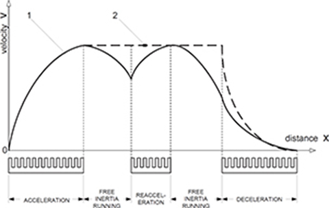
Fig. 9.18. Speed profiles of LSM horizontal transportation systems. 1 — discontinuous arrangement of armature units, 2 — continuous arrangement of armature units.
9.3.3 Applications
The horizontal transportation system with stationary short armature units can be used for transfer of containers in storage areas.
The system developed by Preussag Noell, GmbH, Würzberg, in cooperation with the Technical University of Braunschweig, Germany, consists of track-mounted, single-sided, iron-cored armature units and car-mounted movable PM excitation systems [93]. The length of the PM excitation system covers at least two armature units, including the distance between them. A group of armature units connected in series is fed from an IGBT VVVF inverter. The position of cars is detected with the aid of special position sensors. Cars of length up to 15 m run on standard gauge railway track. The air gap between the armature core and PMs is 13 to 15 mm. With the pole pitch from 80 to 100 mm and PM height from 9 to 15 mm, thrust density of 30 to 40 kN/m2 can be obtained [93].
Another LSM system for container transportation has been developed at Kyushu University, Fukuoka, Japan [246]. The air-cored armature coils are distributed along the guideway beneath the container carrier, and the PM excitation system is integrated with the carrier. The air-cored LSM produces both the propulsion force (thrust) and normal repulsive force (no armature ferromagnetic core). The normal repulsive force (electrodynamic levitation) helps to reduce the mass of the payload by about 85% [246]. By applying the decoupled control method, the thrust and normal force can be controlled independently [246]. It is possible not only to reduce the mass of payloads but also to reduce friction, vibration, and noise caused by heavy goods.
Horizontal linear motor transportation systems can alleviate and simplify duties of medical personnel in hospitals. Clinical charts, x-ray films, chemicals, specimens and documents can be transported by linear motor conveyance systems in special containers. Shinko Electric Co. Ltd., Tokyo, Japan has developed linear motor conveyance technology for hospital staff [120]. This system, called LimLinear, can travel both vertically (5 m/s) and horizontally (3 m/s), connects several floors, and is controlled by computer.
Examples
Example 9.1
Consider a ropeless elevator introduced in Example 1.6 (Chapter 1). The mass of the fully loaded car is m = 4583 kg (with 16 passengers), acceleration/deceleration a = 1.1 m/s2, speed v = 10.0 m/s, and LSM efficiency η = 0.97. It is assumed that the hoistway efficiency is 100%. Analyze the motion, thrust, power, and energy profiles in the time t domain for a car ascending and descending the hoistway 1000 m high.
Solution
Car going upward—Acceleration
The time to reach the full speed v = 10.0 m/s, i.e., acceleration time
The travel distance at the end of the acceleration phase
The thrust required to accelerate the mass m = 4583 kg upward with acceleration a
The peak input power at the end of the acceleration phase (t = t1)
Energy delivered to the LSM during the up-acceleration phase
Car going upward—Steady State
The elevator car is cruising up with constant speed v = 10.0 m/s, and acceleration is equal to zero, (a = 0.0). The duration time of the steady-state phase is calculated on the assumption that the car accelerates and decelerates with the same rate |a| = 1.1 m/s2. Then, the deceleration time td as well as the corresponding distance hd is the same as the acceleration time ta = t1 and acceleration distance ha, i.e.,
where t3 is the total time of traveling from start to stop. Then, the travel distance during the steady state is
The duration of the steady state
The steady-state thrust
The LSM steady-state input power is independent of time, i.e.,
Energy delivered to the LSM
Car going upward—Deceleration
The time instant when the car starts to decelerate, t2 = t1+ts = 9.09+90.91 = 100.0 s.
The thrust directed upward that is required to maintain the deceleration of 1.1 m/s2
Energy delivered to the LSM during the up-deceleration phase
The total energy consumed by the LSM during the travel up
Car going downward
To keep the acceleration and speed at acceptable levels, the LSM operates as a brake (plugging) during the entire period of downward travel. The LSM produces the force directed upward limiting the acceleration to 1.1 m/s2. The regeneration starts when power developed by moving masses exceeds linear motor losses. Calculations conducted in the same way as for a car going up produced the following results:
Car going downward—Acceleration
Time to reach contract speed v = 10.0 m/s, ta = 9.09 s
Car position at the end of the acceleration, h(ta) = 954.55 m
Distance traveled during acceleration, ha = 45.45 m
Thrust required to keep acceleration at 1.1 m/s2, Fxa = 39.918 kN
Time to start regeneration, tch = 0.34 s
Generated power at the end of acceleration, Pina = 194.0 kW
Energy for downward acceleration, Ea = 1, 755 kJ
Car going downward—Steady State
Braking force in steady state, Fxs = 44.96 kN
Power generated by the LSM at steady state, Pgs = 436.0 kW
Generated energy, Es = 39, 637 kJ
Car going downward—Deceleration
Upward thrust to maintain the deceleration of −1.1 m/s2, Fxd = 50 kN
Generated power at the beginning of deceleration, Pgd(t2) = 485.0 kW
Energy recovered during deceleration, Ed = 2, 198 kJ
The total energy recovered when traveling downward
One fully loaded car descending down generates 43,590 kJ energy, which is returned to the power system.
The energy balance for one fully loaded car for a round trip is
It means that the fully loaded car (with 16 passengers) during one round trip consumes only 2,805.0 kJ energy.
The hoistway cycling energy efficiency, defined as the ratio of energy recovered during the descent of a fully loaded car to the energy consumed by this car during the ascend, is
For comparison, Fig. 9.19 shows the speed, power, and energy versus time curves measured for the roped elevator with propulsion system based on the tandem of LIMs. This experimental system was built and tested by Otis Elevator Company in the early 1990s. The elevator was driven by two flat linear induction motors installed in the counterweight running over long stationary reaction rails consisting of copper backed by a steel plate. The elevator was capable of carrying 16 passengers between 7 floors with 2.5 m/s rated speed. The peak 20,000 N thrust has been developed by the tandem of flat LIMs during the acceleration phase. The energy curve (Fig. 9.19b) shows that even for a fully loaded car going downward, the total energy at the end of the cycle is positive. This means that the energy supplied by the power system exceeds that generated during regenerative braking. This is due to the relatively low efficiency of LIMs. In the considered example, the peak LIM efficiency is 43%.
Example 9.2
Consider a 250 story, 1,000 m high hyper building, with population of 100,000 people. The elevator system consists of 17 ropeless hoistways with fifty 16-passenger cars each, plus two additional ropeless hoistways containing 20 cars each and serving 13 floor zones for interfloor traffic. Analyze the energy usage by the system for 24 hours a day.

Fig. 9.19. Velocity, power, and energy for flat linear motor roped elevator system with counterweight: (a) ascending car, (b) descending car. Courtesy of Otis Elevator Company, Farmington, CT, USA.
Traffic scenario
Up-peak (morning) and down-peak (evening) periods: 10,000 passengers/5 min, duration 1.0 h at peak load and 1.0 h at 50% load both in the morning and evening
Peak period interfloor counter flow: 1% of up-peak during peak periods, e.g., in the morning nearly all passengers travel up; however, about 1% go down—in counter flow direction
Mid-day peak period: 50% nominal off peak period, duration 2.0 h at lunch time
Traffic configuration
50 cars/hoistway, each car with destination to 5 floor group—stops at each floor of the group
Nominal round trip time = 400 s
Car size: 4583 kg, 16 passengers, (3483 kg empty car +1100 kg duty load)
Motor efficiency η = 97% (propulsion and regeneration)
Time for car to reach top floor = 110 s
Time to service next 4 floors = 18 s per floor (4 s floor–to–floor run, 4 s door time, 10 second enter–exit)
Assumptions
There are no friction losses (due to the noncontact guidance system), and no windage losses are taken into account. The power requirement for guidance, control, lighting, and ventilation is neglected. Similarly, the power to move in transverse direction in the loading areas is not considered.
All cars in 17 fast traffic hoistways are assumed to be full when leaving the lobby and empty upon return. The up-peak energy analysis is based on fully loaded car operating at full propulsion power (calculated in the previous Example 1—car running to the highest floor) for the entire run time to the first stop at the lowest floor serviced by each car. The regenerated energy for the down run has been calculated on the basis of previous Example 1 with the 3483 kg mass of empty car used in all equations.
Energy usage by the two interfloor hoistways is calculated on the basis of the following: the average load of a car is 50%; the extra acceleration power is offset by the reduced deceleration power; cars are making an average of four 3-floor runs up plus another four 3-floor runs down in each round trip with three 7.0 s interfloor stops. The two interfloor hoistways together can carry 733 passengers up and another 733 passengers down in each 5 min period, at 50% capacity. If required, the nominal 50% capacity can be upgraded to the full capacity with higher number of passengers.
Solution
The ropeless elevators are estimated to consume approximately 255,000 kWh (255 MWh) of energy during a 24 h day. This number has been obtained from computer simulation using a dedicated software. The highest power is necessary for the 1 h up-peak period. During that time, the elevator system, i.e., all elevators, require approximately 49,500 kW power for the peak load.
It is interesting that this peak power consumption, considered together with typical linear motor efficiency, yields a thermal dissipation of approximately 11,500 kW (power losses in all LSMs) during that one peak hour. It should be mentioned that thermal dissipation is considerably less at all other times of the day. Most of the heat is generated in the armature windings of LSMs since PM excitation systems do not generate power losses. The estimated heat dissipation leads to the conclusion that an effective cooling system must be applied directly to the armature windings. Preferably, the cooling system should use a chilled liquid rather than the air flowing directly through cooling ducts in the armature. It is interesting to note that one person can generate during 1 h approximately 0.117 kWh of thermal energy in an office environment. The 100,000 occupants in the hyper building collectively generate about 11,700 kWh, or roughly the same amount as that of ropeless elevators during the 1 h peak period. Thus, the energy usage by the air-conditioning system is comparable with elevator energy converted into heat losses.