
Chapter 2
Diversity of design
Although the original moving-coil, cone loudspeaker of Rice and Kellogg was the first true loudspeaker of a type that we know today, it was, itself, a development of ideas which had gone before, principally relating to the design of telephone earpieces, which were not very loud speakers. The moving coil direct radiator, along with amplifiers as great as 15 watts output – which was then huge – soon opened a door to room-filling sound levels, and, within only a couple of years, talking pictures at the cinema. The need to fill larger and larger theatres with sound led to horn designs, and the need for greater bandwidth led to the separation of the drive units into frequency ranges where they could operate more efficiently. Thus began a refinement and specialisation of designs which continues to this day, with ever more ideas, magnet materials, diaphragm materials and radiator concepts all designed essentially to do the same thing – convert electrical energy into sound waves. What follows in this chapter is a discussion of some of the various ways in which this conversion can be made to take place, and the strengths and weaknesses of the various approaches.
2.1 Moving-coil cone loudspeakers
Of all types of drive units, there is probably none so varied in size, shape, materials of construction or performance as the moving coil cone loudspeaker. They basically all follow the concept shown in Figure 2.1, and little has changed in the underlying principles of their operation in the 80 years of existence so far. They all need a magnet, which was often an electro-magnet in the early years before permanent magnets of sufficient strength were developed. In this case, a ‘field coil’ was supplied with a DC current sufficient to generate the required strength of magnetic field for the ‘voice coil’ (which was fed with the output signal from the amplifier), to drive the cone with the required level of sensitivity. Early permanent magnets were often made from iron and chromium. Aluminium, nickel and cobalt were variously used in the early 1930s, alloyed with iron in different combinations, and the three together gave rise to the name Alnico. In the 1970s, the civil war in the Congo (then Zaire) created a big hole in the production of cobalt, whose price rose astronomically in a very short period of time. This led to the use of ferrite materials, known as ceramic magnets, which had their strengths and weaknesses which will be discussed in Section 2.1.6. More recently, ‘rare earth’ magnets, principally made from neodymium and samarium based alloys, such as neodymium with iron and boron, or samarium and cobalt, have led to very light weight magnets, and opened a door to new magnet shapes and magnetic field designs. The basic concept of two different magnet structures is shown in Figure 2.2.
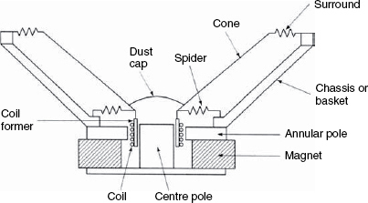
Figure 2.1 The components of a moving coil loudspeaker
The magnetic circuits are designed to concentrate the magnetic field in a circular gap, as shown in Figure 2.3. In this gap is inserted the voice coil, which receives the electrical drive current from the power amplifier. This current produces its own, alternating magnetic field, whose phase and amplitude depend on the drive signal. The variable field interacts with the static field in the circular gap, and creates a force which either causes the voice coil to move into or out of the gap. Of course, a means is required to maintain the coil centralised in the gap, and this is achieved by the use of centring device, or inner suspension, which is still often referred to as a spider for reasons which should be clear from an inspection of Figure 2.4. A more typical modern device is shown in Figure 2.5. A chassis, also known as a frame or basket, supports the whole assembly and enables it to be mounted on a front baffle. The cone is connected rigidly to the former upon which the voice coils is wound, and is also connected more or less at the same point to the inner suspension. At the chassis’ outer edge the cone is attached via a flexible outer suspension, or surround, which may take the form of half-rolls, corrugations, or pleats. These will be discussed in more detail in Section 2.1.2. A dust cap is then normally placed in the apex of the cone in order to prevent the ingress of dust and any abrasive dirt, and may also be used as an air pump to cool the voice coil and gap when the cone assembly moves in and out.
2.1.1 Cones
A three-way loudspeaker system consisting entirely of cone drivers is shown in Figure 2.6. Although the cone drivers all follow the above principles of construction, their designs are very different. In Chapter 1 it was explained how, at low frequencies, the electro-acoustic conversion efficiency is low, because the air tends to move out of the way of the vibrating cone. The result of this is that for a reasonable on-axis sensitivity, the cone needs to be quite large. In the loudspeaker shown in Figure 2.6, the low frequency cone is of nominally 12 inch diameter (300 mm), although the effective radiating area is only just over 10 inches because the surround does not contribute much to the radiation. The cone needs to be rigid, because if it breaks up into non-uniform movement, phase cancellations will occur at some frequencies and the subsequent frequency response will not be flat. In some cases, cone break up can be used to extend the frequency response, and can be used in musical instrument loudspeakers to create desirable colouration in the sound, but for flat, uncoloured low-frequency responses, the piston which is pumping the air needs to maintain its rigidity. Some of the ways in which a cone can break up are shown in Figure 2.7.
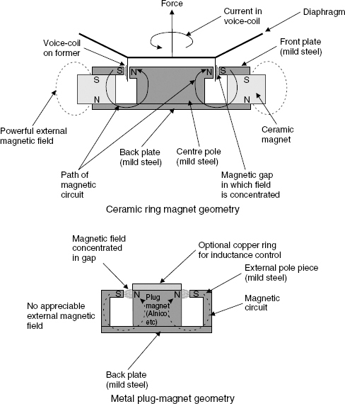
Figure 2.2 Typical motor topologies
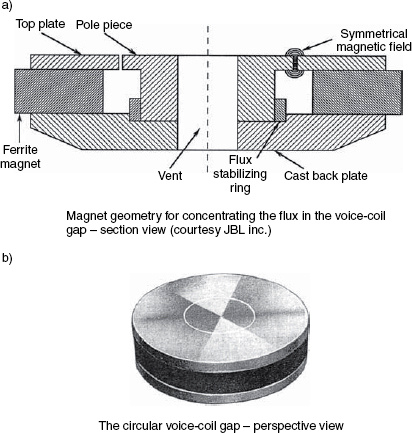
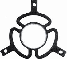
Figure 2.4 An early centring device – a ‘spider’, some of which had more legs than the one shown
Once cones exceed a diameter of about 18 inches (460 mm) it can become difficult to maintain their rigidity. The gain in efficiency due to the large radiating areas of big drivers can rapidly be offset by the greater proportional weight needed to keep them rigid. Many designers favour multiple, smaller drivers to the use of single larger drivers partly because they feel that they can keep these better controlled. It is unusual to see drivers of greater than 18 inch diameter, although they do exist, as shown in Figure 2.8. Sandwich cones, honeycomb cones and Kevlar and carbon fibre and metal cones have all been employed in attempts to maintain cone rigidity, and consequently the pistonic movement. In each case, the cones exhibit different characteristics above certain frequencies, so the suitability of each material or construction may depend upon the upper frequency limit to which a driver will be used. Solid cones have also been used, but they can introduce as many problems as they solve, and they are not so obviously beneficial as they may at first appear to be. One problem with many of these approaches has been that the near-perfect rigidity has improved matters at low frequencies but has only pushed the resonances up in frequency, rather than eliminating them. When stiff structures do break up they tend to do so much more severely, so crossover frequencies must be chosen well away from the break-up frequencies if colouration is to be avoided. It has proved difficult to achieve uncoloured mid-range responses from highly rigid low frequency driver cones, so they are often best restricted to use at low frequencies only.
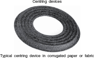
Figure 2.5 A typical, modern centring device, or inner suspension
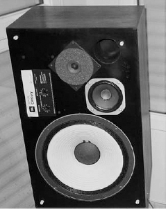
Figure 2.6 A full-range, all cone driver loudspeaker system – the JBL L100
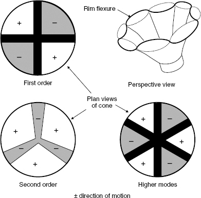
Figure 2.7 Bell-mode break-up in cones
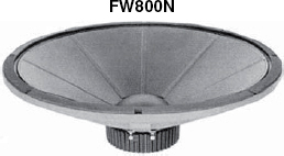
Figure 2.8 A very large loudspeaker – a 30 inch (800 mm) low frequency loudspeaker with radial reinforcing ribs to augment the cone rigidity
Bextrene, a mixture of polystyrene and neoprene, was pioneered as a cone material by the BBC, in the UK, as far back as the 1960s. This was originally researched largely to find a solution to the inconsistency problems encountered in the manufacture of paper pulp (cardboard) cones. Paper, being made from wood, which is a natural material, can suffer from the problem of all natural organic materials; they are not homogeneous substances so they tend to vary from batch to batch. Bextrene was well-damped and resisted break-up to relatively high frequencies. Designs have been employed using Bextrene cones which have used 12 inch (300 mm) bass drivers up to crossover frequencies beyond 1.5 kHz with little mid-range colouration. Polypropylene has since been developed for use as a cone material, offering even more consistency, long term stability and sensitivity. However, opinions vary about the sonic neutrality of polypropylene-coned drivers.
The original loudspeaker of Rice and Kellogg used a paper cone. Quite remarkably, despite all of the modern developments in materials and construction, paper pulp cones, and even folded and seamed paper cones, are still in use in all levels of performance ranges. Paper pulp cones are made by drawing a slurry (wet mix) of paper fibres through a fine screen in the required shape. The resulting cone is then cured and dried before being cut to the exact size required. This ‘old fashioned’ material still exhibits excellent characteristics of high rigidity and high internal damping, and these are two things which normally are contradictory inasmuch as the augmentation of either one usually tends to reduce the other. At low frequencies the rigidity is necessary to maintain piston action, but once any break-up does begin, the internal damping of the cone material needs to suppress the waves which travel as shown in Figure 2.9, which would cause peaks and dips in the frequency response. The bass cone shown in Figure 2.6 has been further treated on both sides with a damping material known as Aquaplas, which also adds some mass, and this lowers the free-air resonance of the driver.
Despite the fact that many drive units of similar specification which employ different cone materials may perform very closely in objective measurement, there is strong evidence that some very similarly performing drivers do not sound the same. In very high quality loudspeakers, paper pulp is still a favoured material, despite its sensitivity to humidity and batch-to-batch variation. Colloms1 refers to the well-balanced characteristics of paper pulp, together with the fact that its properties and manufacturing techniques are well-understood, as strong justification for its continued use. He notes how some high-loss materials also may tend to lose, or mask, fine musical detail. The authors of this book have noticed a loss of reverberation detail when substituting some synthetic cones for paper cones used up to 1 kHz, and have received comments from professional users about guitar strings not sounding as new when heard via the synthetic cones as when heard via high quality paper pulp cones. The Celestion loudspeakers company still produce the exact model of guitar loudspeaker which was made famous in the Vox AC30 guitar amplifier of the 1960s. This blue-chassised driver has resisted all efforts to update its construction, yet still maintain its highly desirable sound qualities. A great number of musicians claim to hear their guitars more ‘clearly’ via paper cones.
The observations about guitar strings could suggest a harmonic enhancement due to non-linear distortion products enriching the sound, but harmonic distortion could not explain the increased sensation of low-level detail and reverberation. Synthesising natural sounding reverberation is not something which one would expect from the addition of harmonic distortion. It seems probable that the guitar strings are benefiting from the same characteristics which are enabling the greater resolution of reverberation and room effects, and paper-pulp seems to be a good performer in this respect. Work is currently under way to investigate the possibility of intermodulation distortion contributing to the low level detail loss with certain materials, given rise to by non-linear hysteresis effects connected with the damping action. Intermodulation distortions will be discussed in more detail in Chapter 9, but it results in harmonically and non-harmonically related products which together tend to produce a noise signal below the music.
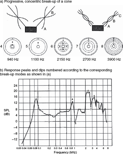
Figure 2.9 Concentric modes in loudspeaker cones
As the frequency rises, two things begin to affect the performance of a cone driver. It was shown in Figures 1.3. and 1.4 how the directivity of a cone, or any pistonic radiating surface, narrows as the wavelength become small compared to the circumference of the radiating area. However, as frequencies rise, the mass of the moving assembly gradually tends to oppose more strongly the force which is trying to move it. There comes a point where the increasing efficiency of radiation due to the greater radiation resistance provided by the air as the frequency rises can no longer compensate for the mass effects of the moving parts, and the power response of the driver begins to roll off. For a 15 inch (380 mm) loudspeaker, 1 kHz is about the upper limit of either its flat response range or the acceptability of its narrowing directivity. Nevertheless, the directivity narrowing may not be too severe if the centre section of the cone begins to decouple itself from the outer section, as often happens – either by design or accident. Eight inch loudspeakers (200 mm) can work well up to 2 kHz, or more, but the compromises which must be made if their responses are to be extended at the bottom end may begin to degrade the higher frequency performance. In the loudspeaker shown in Figure 2.6, the 12 inch (300 mm) low frequency driver, having a free-air resonance of 25 Hz, is used up to a frequency of around 1 kHz, at which point the crossover begins to divert the signal towards the 5 inch (125 mm) cone. Five octaves is just about the limit of the bandwidth of a cone driver if very high quality, wide directivity, minimum-compromise sonic performance is required.
In smaller loudspeakers, cone rigidity is much easier to achieve, therefore much lighter moving assemblies can be employed which can exhibit good efficiency without the massive magnet assemblies needed for the low frequency drivers. The low frequency driver shown in Figure 2.6 has a sensitivity of 89 dB for 1 watt input at 1 metre distance, yet with a much smaller magnet but a lighter moving assembly, the 5 inch mid-range driver has a corresponding sensitivity of 94 dB. This sensitivity increase can be important, because smaller loudspeakers cannot lose the waste heat as easily as can large loudspeakers, which was one driving force behind the developments of domes, as will be discussed in Section 2.2. The tiny tweeter cone shown in Figure 2.6 is only 1½ inches (38 mm) in diameter, but handles frequencies from 4 kHz to almost 20 kHz, so in this design of loudspeaker cabinet all frequencies from below 40 Hz to almost 20 kHz are handled by paper cones.
2.1.2 Surrounds
The outer suspension, or cone surround, serves two functions. The most obvious is to maintain the outer edge of the cone stable during the rapid movements along the front-back axis, but surrounds also serve to absorb vibrational waves which propagate from the voice coil in the manner shown in Figure 2.9. A selection of surround designs are shown in Figure 2.10. The surrounds are variously formed from a continuation of the cone material or from separate materials attached with adhesives. Polyurethane foam, butyl rubber, nitryl rubber, cambric (pronounced Kāymbrik - a woven linen or cotton fabric), or other treated fabrics are frequently used as cone surround materials. PVC is also sometimes used. Figure 2.10(a) shows a half-roll surround. These are usually made from synthetic foams or rubbers. They allow long travel because they tend to stretch in an elastic manner over a considerable range of movement, and hence give rise to little distortion which would be caused by restraining the cone travel. When the materials are carefully chosen they can effectively absorb the resonant modes which pass radially along the cone, thus avoiding standing waves within the materials of the cones. The double half-roll surrounds, shown in Figure 2.10(b) are usually made from treated cloths. They are more rugged than the single half-rolls, and find much use in sound reinforcement and musical instrument amplification, but tend in general to be used in less long-throw loudspeakers with higher resonant frequencies than those which usually employ the single half-rolls. The extra stiffness of the double half-roll surrounds both adds to their ruggedness and increases the resonant frequency of the moving system as compared to single half-roll devices. Figure 2.10(c) shows a concertina (accordion) surround. These are often pressed or moulded as part of the cone. They can allow extended travel, but unless very carefully damped can give rise to resonance problems. They also tend to be stiffer than the single or double half-roll surrounds, and are therefore not often found on low-resonance designs.
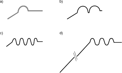
Figure 2.10 Cone surround variants. a) Half-roll of polyurethane foam – low stiffness (high compliance) for long travel, but requires precise choice of centring device for controlled linearity. b) Double half-roll cloth – shape of rolls can precisely tune the stiffness characteristic. c) Multiple-roll accordion pleat – long travel but prone to rim-resonance response dip problems (see Figure 2.11). d) One piece cone/surround with treated edge – stiff, non linear suspension, provides HF resonance peak. Principally used for musical instrument loudspeakers to prevent over-excursions of the cone
Surround materials are also a specialised subject. Some of the foams which are commonly used can deteriorate much quicker than expected in sunlight or polluted atmospheres, and can also suffer from insect damage. Nevertheless, in clean, temperature-controlled environments such as exist in many sound control rooms they can easily last for 20 years or more, and can be replaced by skilled artisans without removing the cone from the chassis. Plasticised PVC is another material which has been employed with success, and is found on some mid-range cones where its properties efficiently absorb the waves reaching the cone edges. In sealed cabinets, the surrounds must also resist the differential pressures between the inside and the outside of the cabinet, and this fact can preclude the use of some foams in certain cases. In order to fulfil all of the demands made of them, surrounds are quite specialised devices. The surrounds not only need to be selected according to the density of the cone material, but also the principal frequency ranges over which a driver will work, and the excursion limits within which they must allow relatively unrestricted movement. For wide-range drive units, the compromise choices are not simple. Figure 2.11 shows a response dip due to an antiphase movement of a surround. The fact that the dip exists in the response of such a high quality driver suggests that solutions to the dip problem would have compromised the overall response to a greater degree.
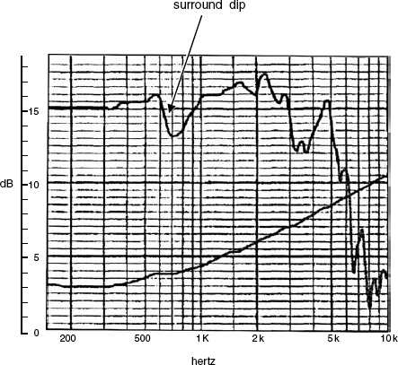
Figure 2.11 Response dip due to a surround resonance
2.1.3 Rear suspensions
The prime function of the rear suspension, or spider, is to maintain the coil centralised in the magnetic gap. On its inner edge it is connected to the voice coil former, and at its outer edge it is glued to the chassis. Modern suspensions, such as the one shown in Figure 2.5, are usually made from phenolic resin impregnated cloth, hot pressed into shape. Care has to be taken in the design of the corrugations to ensure that movement in one direction is not favoured over the other direction, because an asymmetrical movement would give rise to non-linear distortion. Some designs have employed double spiders, mirror imaged, in order to ensure symmetrical linear travel of the cone. A double spider arrangement is shown in Figure 2.12. These are fine in vented magnet designs, but a complication in double suspension designs arises if they must allow air to pass through to cool the voice coil in designs that do not have vented magnet systems. As with the corrugated, concertina surrounds, the corrugated inner suspensions can suffer from resonance problems unless they are carefully ‘tuned’.
The stability of the inner suspensions needs to be very good because the gap between the voice coil and the magnet can be less than half a millimetre, even with a relatively large cone and coil. With large, heavy cone/coil assemblies, the suspensions can become stretched if the drivers are stored in a horizontal position without adequate support for the cone (which effectively means in the manufacturers’ shipping boxes). Likewise, complete loudspeaker systems should not be stored on their backs or ‘cone sag’ is likely to result. Once mounted vertical again, the suspension may have ‘set’ to a new equilibrium position which is not in the centre of the cone's axial travel, hence the cone excursion will be prematurely limited in one direction. In many cases, this cone sag cannot be corrected by any simple means, and so storage conditions likely to give rise to it should be avoided.
The inner suspension is very critical because it usually provides the main restoring force for centralising the cone in the axial as well as the radial directions. Over 50 years ago, Briggs recognised not only the third-harmonic distortion-producing mechanisms of badly designed suspensions, but also the fact that inadequate suspensions could give rise to distorted transient responses2. Over 40 years later, Colloms wrote about work done at KEF which correlated well with his own experiences that some inner suspensions could give excellent, low distortion results on sine waves and the more open bass waveforms of orchestral music, but could be slow in responding to the more percussive bass sounds found in much modern music1. The KEF findings had emerged from investigations into the different low frequency measurements obtained via the use of steady state or impulsive signal sources. [These test methods are described further in Chapter 9.] The differences have been attributed to hysteresis in the suspensions, shown diagrammatically in Figure 2.13.
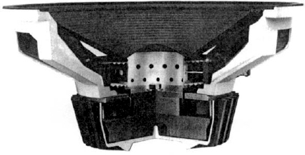
Figure 2.12 Cut-away view of a 380 mm loudspeaker with double spider (centring device) construction (Cetec-Gauss Inc)
In some very small cone loudspeakers, designed only for high frequency use, the additional complexity of the use of an inner suspension can often be omitted, the external surround being sufficient to maintain the cone in a central position, and thus avoiding all the inner-suspension-related problems which larger, heavier cones must endure.
Although the suspension systems, both surrounds and spiders, are mechanically essential in low and mid frequency cone loudspeakers, towards their excursion limits they all begin to give rise to third harmonic distortion due to the approaching elasticity limits where they become less compliant (i.e. more stiff). Once they no longer obey Hooke's Law (the law governing the relationship between force and compression [or expansion] of a simple spring) they can produce quite a number of undesirable artefacts.
2.1.4 The chassis
Loudspeaker chassis provide a frame for the mounting of the magnet system and inner and outer suspensions. They can be made of plastic, or pressed or cast metal. Metal is preferred when power levels are high because it helps to conduct the heat away from the magnet assembly. Cast metal is usually preferable to pressed metal on grounds of stability and dimensional accuracy; cast aluminium being the material of choice for most large professional bass units. With magnet assemblies weighing 10 kg or more on some 18 inch loudspeakers, the chassis (‘frames’, ‘baskets’) need to be strong to withstand shipping shocks without disturbing the centralisation of the sub-half-millimetre coil clearances. Also, coil temperatures of 250 degrees C, or over, need to be withstood and dissipated without warping. Unfortunately, there is a conflicting requirement between the strength of the chassis and the need not to impede the free movement of air between the cone and the inside of the box (or outside the box in the case of external chassis designs, as shown in Figure 2.14). The chassis therefore needs to be as strong as necessary for support, whilst being as open as required for non obstruction of the air adjacent to the cone. It is also important that it should not suffer from resonance problems, and so needs to be well acoustically damped.
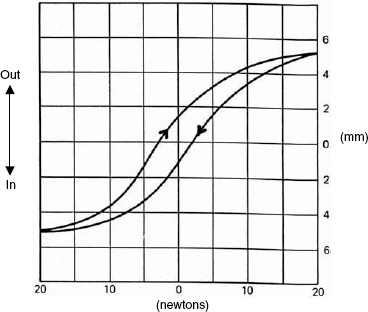
Figure 2.13 Hysteresis curves – the hysteresis curves represent processes which are cyclic but where the forward and backward processes do not follow the same path. ‘Hysteresis’ is from the Greek word meaning ‘to lag behind’
Once a cone and coil assembly is mounted in a chassis at the surround and the inner suppression attachment points, its mass will resonate with the compliance of the suspension systems to determine the free air resonance of the driver. The free air resonance normally defines the lower response limit of a loudspeaker system in any given volume or design of cabinet. However, there do exist some special designs of loudspeaker systems which drive the bass units through their resonances, but they are rare, and need electronic compensation.
2.1.5 The voice-coil assembly
The voice-coil former is normally attached to a cone at some point between its apex and a point mid-way between the apex and the perimeter. The coil former, of cylindrical design, must be mechanically stable under high degrees of vibration and temperature changes, neither deforming in circularity nor expanding or contracting to any significant degree. Without the required stability, the coil or the former could rub on the sides of the magnetic gap and make undesirable scraping noises. Although paper was used to great effect on early, low-power loudspeakers, modern day, high-temperature voice coils need to be bonded to thermally stable formers with thermally stable adhesives. Glass fibre has been used as a former material, but polyamides are now more normal, (Nomex, Kapton etc). Aluminium has also been used, but metal formers can suffer from eddy current problems by acting as a shorted turn in the alternating magnetic field, and can also conduct very high temperatures to the necks of the cones, where charring, melting or softening can occur, and adhesives may also be caused to fail.
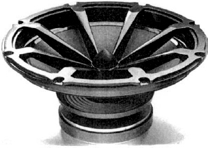
Figure 2.14 A 15 inch (380 mm) loudspeaker manufactured by the British company Volt Loudspeakers Ltd, employing an external chassis for improved heat dissipation
The coils are almost exclusively made from copper or aluminium, although silver has also been used, reportedly to some sonic benefit1. Copper offers lower resistance, but aluminium offers lighter weight. Which one is the most appropriate depends on many other design factors, but both materials have been used at either frequency extreme – there are no hard and fast rules. Copper clad aluminium is another option, which simplifies the soldering problems which may be encountered with pure aluminium. Round wire and rectangular section (ribbon) wire are also options. The ribbon wire packs more densely, eliminating the gaps between the adjacent round wires, but round wires offer much simpler winding processes. To prevent short circuits between turns, the copper wire is insulated with a heat resistant lacquer, and aluminium wires are anodised, which creates a layer of non-conducting aluminium oxide on the surface. In either case, the wires may also be coated with a thermosetting adhesive before winding, which, after curing, helps to render the entire assembly more rigid.
The most appropriate diameter of a voice coil is also the subject of compromise. Larger diameter voice coils have more surface area for any given length of wire than coils of less diameter, at least for any given gap depth, and can therefore lose heat more easily. They can also help to stiffen a cone by driving it in a more evenly distributed manner. However, if the coil is too big in diameter, the centre of the cone can begin to decouple from the coil, which can cause strange frequency response and directivity problems. Proponents of small diameter voice coils cite advantages of deeper coils in longer gaps giving them design advantages such as deeper gaps with less magnetic material at no thermal dissipation cost. As with so many things in loudspeaker design, the art of the science is finding the best compromise for any given situation. Low frequency efficiency versus high frequency extension, for example, can dictate the optimum choice of coil material as copper or aluminium. Some manufacturers have also great expertise in using particular design concepts or manufacturing processes which suit certain ways of doing things better than others. Electro-Voice, for decades, continued to make excellent 15 inch (380 mm) loudspeakers with 21/2 inch (62 mm) voice coils, whilst JBL had long since moved to 4 inch (100 mm) coils for their equivalent designs, but using different magnet topologies.
2.1.6 Magnet systems
The voice coil and the magnet form the motor system of a moving-coil loudspeaker. As mentioned above, either one depends on the other in order to produce the required force to drive the cone in the required direction at the required speed, as instructed by the electrical input signal. Magnets are a huge and complex subject in themselves, so only some of the more fundamental aspects of their behaviour can be dealt with here, but the Bibliography at the end of this chapter gives references to some excellent further reading. Cost, however, perhaps plays a bigger part in the choice of magnet systems than in any other aspect of the design of cone loudspeakers. Some of the best magnetic materials ever developed for loudspeaker use used cobalt, which, as mentioned in Section 2.1, rose in price by over 2000% in a very short period of time when the civil war in Zaire (the former Belgian Congo) began in the 1970s, because Zaire was the world's largest producer of cobalt. This drove many manufacturers to use ferrite materials, predominantly barium ferrite, which had been developed for deriving the static magnetic fields necessary around cathode ray tubes in television sets.
The design of typical Alnico (Aluminium, nickel, cobalt and iron), Ferrite (ceramic), neodymium and Alcomax magnets are shown in Figure 2.15, from which the geometrical differences are obvious, (although the Alcomax and Alnico geometries shown are interchangeable). Many modern loudspeakers use neodymium alloys, and an alloy of samarium and cobalt is also finding use in loudspeaker designs. These materials give enormous magnetic strength for their weight, and they have given rise to further changes in magnetic geometry. The ferrite materials are very resistant to loss of magnetism due to time or heat stresses, but they exhibit powerful stray magnetic fields and can pose some difficulties in achieving the desired magnetic field geometries. Alnico is somewhat less durable, but can allow designs enabling very compact and concentrated magnetic fields. Strength for strength, neodymium magnets are much lighter than either ferrite or cobalt alloy magnets, but can be relatively easily demagnetised at relatively low temperatures, and cannot withstand 250 degrees C voice coil temperatures without permanently losing some of their magnetic strength. The metal magnets are good conductors of electricity, but the ferrite magnets are ceramic materials, and hence are electrically non-conductive. The non-conducting nature of the ferrite materials can be a problem unless careful measures are taken to use other means to avoid unnecessary and undesirable flux modulation effects. Iron of high magnetic permeability is used in the magnetic structures shown in Figure 2.15 to complete the magnetic circuit, and to achieve the correct shape of field and density of magnetic flux in the gap in which the coil is positioned. The type of iron used is normally a mild steel of low carbon content, but when very high flux densities are required, a material known as Permendur is often used, especially in compression drivers. Permendur is an iron-cobalt-vanadium alloy, which is very hard and difficult to work, but its magnetic properties, when required, may demand its use.
There are many people who consider the metal magnets to be capable of better sonic performance than the ferrite magnets, citing better resolution of fine detail with materials such as Alnico and the neodymium alloys. It is hard to find evidence of tests which rigorously compare the differences in the magnetic materials only, because the required structural differences needed to get exactly the same magnetic field in the same gap can lead to other changes being necessary. Nevertheless, there is a tendency for many of the highest resolution devices to use metal magnets, and explanations have been put forward to suggest that the magnetic domain jumps which take place in non-conducting materials can give rise to effects not dissimilar to digital quantising distortion. These jumps are smoothed out by large eddy currents flowing in the electrically conducting magnets. In some loudspeaker designs the central pole-piece of the magnetic assembly is fitted with a copper ring to provide a very low electrical resistance – less than that of steel – to effectively short out any flux-modulation currents.
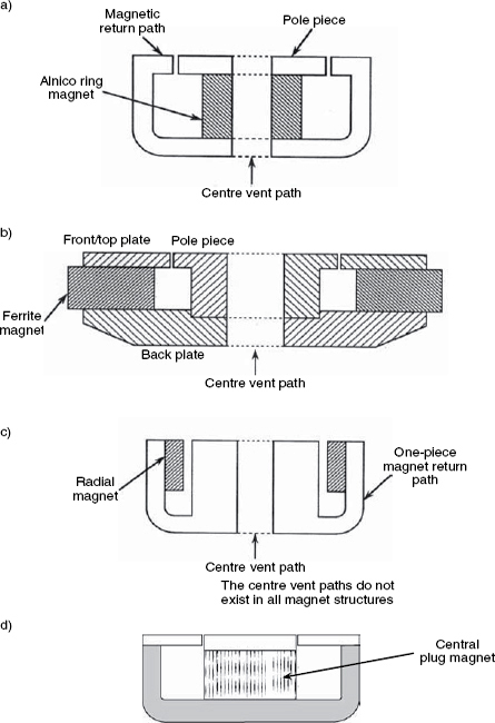
Figure 2.15 Basic magnet structures. a) Alnico ring magnet. b) Ferrite ring magnet. c) Radial, high energy magnet (neodymium etc). d) Alcomax plug magnet a), c) and d) do not have any appreciable external magnetic fields
As shown in Figure 2.15(a), (b) and (c), the entire magnet assemblies in many high-power, low-frequency drivers have cylindrical holes through their central axes to allow air to be pumped through by the dust cover (dome) which caps the voice-coil former on the outer face of the cone. In some other designs, the spider (inner suspension) and the dust cover are of an open weave nature, to allow hot air to pass to the outside of the cabinet. As mentioned earlier, the voice coils can get to temperatures above 250 degrees C in some cases, and this heat needs to be dissipated as quickly as possible, not only to prevent the burn-out of the coil but also to avoid overheating and weakening of the magnet. Furthermore, the resistance of a copper wire rises by about 0.6% for every degree of temperature rise, so a changing voice coil resistance will affect the sensitivity of the motor system and may lead to signal compression.
2.1.7 Ferrofluids
The problem of the conduction of heat from the voice coil to the pole piece of the magnet assembly can, in some instances, be augmented by the use of a ferrofluid. Air is not a good conductor of heat, so much of the heat is transferred from the voice-coil to the magnet assembly by radiation alone. In the 1970s, ferrofluids began to be introduced which were liquids with magnetic particles in colloidal suspension. The magnetic field holds the ferrofluid in the gap, and the good heat-conduction properties of the ferrofluids aids the cooling of the voice-coil by means of a thermal bridge to the magnet assembly. The viscosities of the ferrofluids can be adjusted according to the circumstances of use, a fast-moving tweeter needing lower viscosity than a mid-range driver if viscous damping effects are to be avoided. However, ferrofluids are rarely used in high-excursion low frequency drivers, because the shearing effects of the large axial movements of the coil tend to create non-linear movement due to the non-laminar flow of the fluids. In high frequency drive units, the ferrofluids can be advantageous in damping some mechanical resonances if the viscosities are chosen appropriately.
2.1.8 The complete system
The moving coil cone loudspeaker is quite remarkable in its degree of versatility of application, and has formed the backbone of loudspeaker system design since its first application in 1925. Despite all the technological developments and improvements in materials, Rice and Kellogg, if still alive today, would almost certainly be able to explain the workings of any modern moving coil loudspeakers from simple inspection. When they filed their patent, they already had described, in principle, almost everything that we can find in a modern driver. Loudspeaker design is a science; but there is art in deciding about the best compromise points for what are imperfect devices. For example, whether a complete system should use wider range drivers and fewer crossover points, or narrow range drivers and more crossover points, is a question that may depend more on the circumstances of use than any single measurement at a fixed position. Things such as the room acoustics, the music, the required timbral fidelity and the listening distance may all influence a design, but these things will all be discussed later.
2.2 Dome loudspeakers
In general principle, a dome loudspeaker is a cone loudspeaker with the voice coil having the same diameter as the diaphragm. The diaphragm is also usually inverted, to be convex rather than concave to the exterior. A mid-range dome loudspeaker is shown in Figure 2.16. The development of dome loudspeakers largely grew out of the problems surrounding how to lose heat from the small voice coils of mid and high frequency drivers at high power levels. A 1½ inch (38 mm) cone tweeter, with a coil of only 12 mm diameter simply cannot lose heat quickly enough to prevent itself from burning up at power levels much above 10 watts, because the heat production is all confined in a small space. However, if the coil were to be made the same diameter as the diaphragm, a much greater surface area would be available for heat loss. As light weight is important for sensitivity, the coil former can be kept to a minimum length if the dome diaphragm is convex because it will remain clear of the pole piece of the magnet assembly, as shown in Figure 2.17.
Despite the ‘common sense’ belief of many people that domes radiate over a wider angle than cones, this is not so. It is important not to confuse domes with pulsating spheres. As shown in Figure 2.18, a pulsating sphere, which would radiate radially, moves by expanding and contracting in three dimensions, whereas a dome simply radiates as a piston, because it moves in one direction only – along its axis of movement. What is more, when a cone begins to decouple from its voice coil, it does so from the outer parts first. The central part, nearest to the voice coil, always remains under the control of the coil, so the radiating area concentrates towards the centre of the diaphragm as the frequency rises, which is exactly what is needed to maintain its directivity. That is, the radiating area reduces in diameter as the frequency rises, which can be desirable. Conversely, with a dome, it is the centre of the radiating area which is furthest from the coil, so as the frequency rises the tendency is for the voice coil to keep control over the outer perimeter of the radiating area, whilst the centre of the diaphragm decouples itself, as shown in Figure 2.19. This leads to a ring radiator, which has very peculiar directivity properties, so domes, if not applied very carefully and below their break-up frequencies can actually have less smooth directivity than cones.
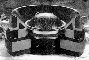
Figure 2.16 A cut-away view of an ATC 3 inch (75 mm) soft dome driver. The British company ATC pioneered the development of this type of high-output mid-range dome
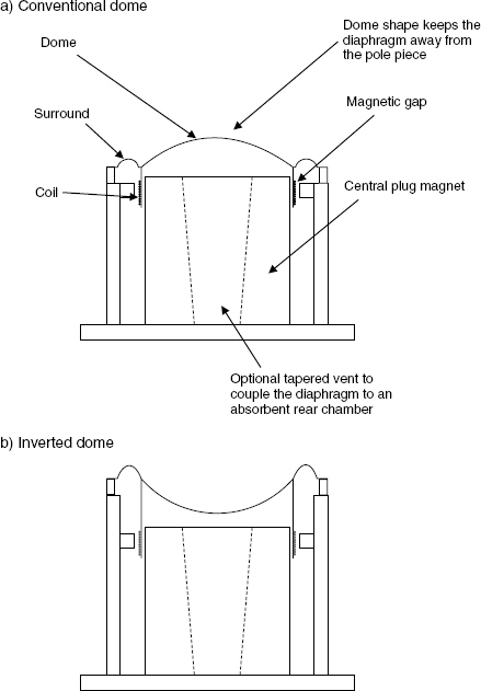
Figure 2.17 A dome as a piston – in principle, if the voice-coil former were to be extended, and the dome inverted (as in b) the sensitivity would drop due to the extra weight, but no material change would take place in terms of the radiation pattern (directivity)
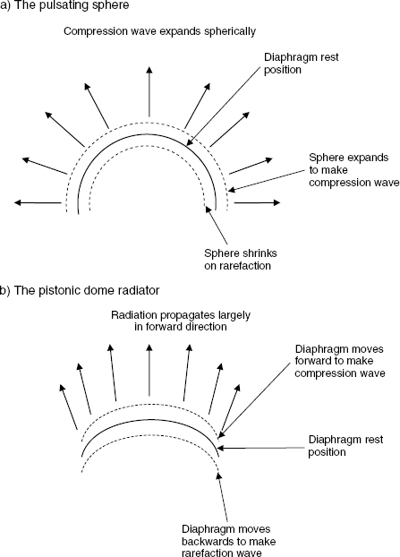
Figure 2.18 Comparison of radiation from pulsating spheres and domes
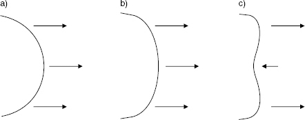
Figure 2.19 A dome in break-up. a) Radiation equal in phase and amplitude from all parts of the dome. b) First bending begins. The radiation amplitude increased from the dome edges and begins to reduce from the centre. c) The dome breaks up. Radiation from the centre becomes out of phase with the edge radiation
2.2.1 Hard and soft domes
The diaphragms of hard domes are usually either made from phenolic-resin impregnated cloth, aluminium, titanium, beryllium, carbon fibre or other, similar materials with very high strength to weight ratios. Soft domes are typically made from moulded cloth which has been treated with a viscous damping material, usually a synthetic rubber. Other types of domes are also sometimes used, as shown in Figure 8.8. Here, a rigid 7 inch (175 mm) dome of polyurethane is used in the lower mid-frequency range. Hard domes are usually restricted to use at high frequencies, above 3 or 4 kHz, because their resonances are difficult to control in diaphragms of sufficient diameter to radiate useful power at much lower frequencies. In rare cases, hard domes of 3 inch (75 cm) or more can be found operating down to frequencies as low as 800 Hz, but in order to maintain piston action up to very high frequencies before the first break-up modes occur, materials such as titanium or beryllium need to be employed. As beryllium is difficult to work with and its vapour is highly toxic, the production of diaphragms out of this metal is an expensive process. Such units have found favour in the design of domestic high-fidelity loudspeakers, but are rarely to be seen in studios. At higher SPL, when they do break up into separately radiating sections, they tend to do so suddenly and in a sonically most unpleasant manner, and produce non-linear distortion products quite differently from soft domes.
Soft domes, on the other hand, can be used down to around 400 Hz, but many exhibit a hysteresis type of response, as discussed in Section 2.1.3 dealing with suspensions, and the same comments apply. The lagging response shown in Figure 2.14 can tend to mask low level detail. The ‘rigid’ domes have been developed partly in response to this problem.
Because of their nature, domes only have an outer suspension. The surround may be formed from the material of the dome in the case of soft diaphragms, but hard domes often employ a separate, bonded suspension material. Rocking motion can be a problem in some designs, and solutions to remedy this are not always practical if they add weight to the moving system, and hence lower the sensitivity, because they may introduce other problems as a result. Lower sensitivity, for example, means more heat in the coil for the same SPL, and can lead to various problems. Ferrofluids can be beneficial in some cases by damping the rocking modes. On rare occasions, double outer suspensions are used. A cross-section of such a construction is shown in Figure 2.20. The choice of material for surrounds can be quite an arduous task in the mid frequencies because the ideal damping properties and compliance (the reciprocal of stiffness) may be conflicting for frequencies two or three octaves apart, yet which must all be radiated by the same diaphragm. At low mid frequencies, where the diaphragm excursion may still be considerable, a cone driver may need to be in a separate enclosure with at least half a litre of air. Dome diaphragms are no different, but the magnetic assembly is an obstruction to the air that is trapped behind the diaphragm, and which tends to push up the resonant frequency. The hollow cavity between the diaphragm and the magnet centre pole, clearly visible in Figure 2.20, is often filled with absorbent material to reduce the cavity resonances. However, if this cavity is too small, it can create problems by way of excessive back-pressure on the diaphragm. Relieving the back pressure may require quite complex boring of the magnetic system if resonances in the tubes and cavities are to be kept out of the working range of the drivers. At high frequencies, these problems are less complex because low resonance frequencies are not required, so neither are such large air cavities required.
Dome tweeters have become very widespread in use, and now probably account for the majority of high frequency drivers. Composite diaphragms are also not uncommon, such as polyester bonded to PVC. Unfortunately, dome tweeters tend to be rather low in sensitivity. This in some ways is ironic, because one of the driving forces behind the development of domes was to overcome the thermal failure problems due to the very small coil surface area in small cone loudspeakers when used at high SPLs. The lower sensitivity of an equivalent dome driver needs more power to drive it, and hence produces more heat. Nevertheless, in many cases, the balance is still in favour of the dome.
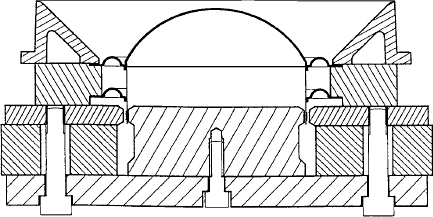
Figure 2.20 Sectional view of an ATC soft-dome driver showing the double suspension which helps to eliminate rocking motion
2.3 Compression drivers
Compression drivers are almost always used with horns, except in some rare cases where their internal throats are sufficient to act as horns for very high frequency use. Essentially, the diaphragm, coil and surround assemblies of compression drivers are rather similar to those of dome drivers. The principle difference lies in the way in which the diaphragm couples to the outside air. In the case of the compression driver, the acoustic radiation passes through a restricted aperture, the ratio of its area to the area of the diaphragm being known as the compression ratio. This puts a highly resistive air load on the diaphragm, which is then passed through a horn of roughly exponential flare rate which prevents the air from moving out of the way of the gradually expanding radiated sound wave. Figure 2.21 shows the cross-section of a typical compression driver, and due to the very resistive load, electro-acoustic efficiencies of up to 50% can be achieved. This means that for every watt of electrical input, only half a watt will be dissipated as heat, and the other half a watt will be radiated as sound. It is thus not unusual for mid and high frequency compression driver/horn combinations to reach sensitivities of over 110 dB SPL for one watt input at one metre distance. Domes, on the other hand, can rarely convert more than 5% of the electrical input into radiated sound, so the other 95% serves only to heat up the voice coil.
Horns are often shunned by many people who have not heard the best examples. Much of this negative attitude has arisen from the days when studio loudspeakers using compression drivers and horns were virtual transplants from the world of sound reinforcement and public address, and once a bad reputation sticks it can be very difficult to lose. To far too many people, because they have heard some bad horns, all horns must be bad. This is the absolute opposite to the general perception of soft dome mid-range drivers, where many people have heard some excellent ones and thus think that they all must be excellent. It is sometimes difficult to understand human reactions to these situations. In neither case is the point of view either logical or correct. It is also worth noting how so many people who state that they do not like horn loudspeakers in the mid range will also say how they like the classic Tannoy Dual Concentric loudspeakers (shown cross-section in Figure 8.7) which, above 1 kHz, are exactly no more and no less than compression drivers and horns.
One problem which does always plague compression drivers is that the sound pressure levels within their throats can reach levels where the air itself cannot linearly propagate sound waves. Air at these SPLs does not compress and rarefy to the same degree under the same applied force in each direction, and so gives rise to harmonic distortion. However, at recording studio SPLs, which are way below live sound and cinema SPLs because of the much closer listening distances, air overload often does not become a problem until levels where direct radiating loudspeakers are suffering from mechanical and thermal non-linearities of their own. When a compression driver made from 5 kg of metal is dissipating half a watt of heat and producing 100 dB SPL for the people behind the mixing console, thermal problems absolutely do not exist, and neither do mechanical stress problems because the diaphragms are moving over such short distances. Non-linear distortions can remain remarkably low, and transient attack can be second to none. The problems with compression driver/horn combinations usually arise when designers fail to respect the physical realities of how to couple the horn to the air, but that will be discussed further in Chapter 4. High sensitivity loudspeakers, in general, also enjoy another benefit in that the lower current in the voice coil for any given output SPL gives rise to much less disturbance of the static magnetic field in the gap, and thus avoid some intermodulation distortion products that are largely unavoidable in less sensitive drive systems when passing high currents through their voice coils.
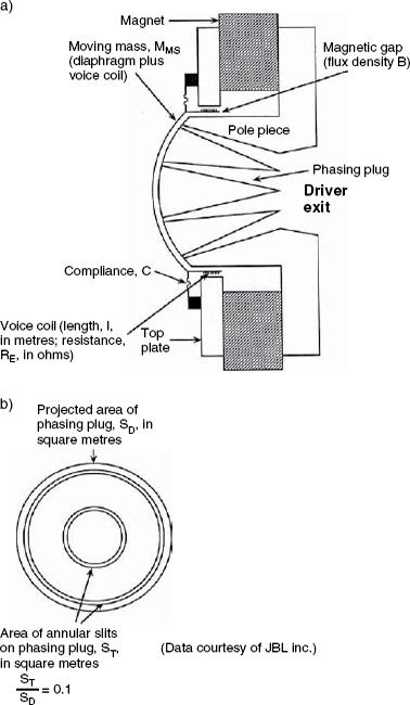
Figure 2.21 A high frequency compression driver (Data courtesy of JBL Inc). a) Section view of a JBL high-frequency compression driver. b) Plan view of the diaphragm side of the phasing plug
Unfortunately, good compression drivers are not cheap to manufacture, because they require precision, low tolerance engineering. It is therefore futile judging compression drivers in general by listening to cheap examples. Tolerances of less than 50 micrometres are not unusual in manufacturing specifications, and the magnetic flux density required in the gap can be so high that special materials may be needed which are difficult to cut and need heat treatment afterwards. Diaphragms also need to be made to very high standards of uniformity whilst often only being about 50 micrometres in thickness. Some of the finest diaphragms are made out of beryllium, because of its enormous strength-to-weight ratio, but its melting point of 1600 degrees C is too high to be accurately moulded in any practicable manner, and rigidity is such that it would shatter like glass if stamped to shape in a press. Some diaphragms are therefore made by a time-consuming and laborious in-vacuo vapour deposition process which is definitely not suited to mass production and is obviously expensive, but 2 inch (50 mm) diameter diaphragms can be made in this manner weighing less than 0.15 grammes, and with frequency responses from 500 Hz to well over 20 kHz.
In order to avoid phase cancellations at high frequencies in compression drivers, a phasing plug is usually incorporated which guides the pressure from different parts of the diaphragm down a series of tubes or concentric slits (as can be seen in Figure 2.21), in order to bring a phase-coherent wavefront to the driver exit, even at the highest frequencies of use. Alternatively, for very high frequency horns used largely only above about 5 kHz, ring diaphragms may be used, as shown in Figure 2.22. These drivers also usually incorporate a short exponential horn as a part of the driver itself, and hence require no external horn. The diaphragms are clamped at the outer and inner edges, and radiate into a ring-shaped aperture which gradually flares into a single exit by means of some sort of central ‘nose’. The sensitivities of these devices range up to about 108 dB SPL for 1 watt input at one metre distance. With a typical power handling capacity of 40 watts, they are virtually indestructible in recording studio or domestic playback use when operating only above about 7 kHz.
Compression drivers tend to work best from about 500 Hz upwards. Below that frequency they can be used, but the horns required to couple them optimally to the outside air tend to become impractically large. The horn shown in Figure 8.2(a) uses a 4 inch (100 mm) diaphragm driving into a 2 inch (50 mm) throat, and is used from around 300 Hz to 20 kHz. This is an exceptionally wide frequency range, although stress loads on the diaphragms can be high at high SPLs. The designer, Shozo Kinoshita, cites smooth directivity and lack of crossover points in the sensitive range of hearing to be great benefits. Certainly the subjective impression from the loudspeakers is one of great low level detail and a rapid transient response which is effortless even at high levels.
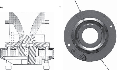
Figure 2.22 Ring diaphragm drivers. a) Section view of a JBL high-frequency compression driver employing a centrally and peripherally clamped ring diaphragm (Drawing courtesy of JBL Inc). b) Photograph of a ring diaphragm
One of the principal differences between the design of compression drivers and dome loudspeakers is that a soft diaphragm is not an option for compression devices. The diaphragms must be light and they must be rigid if high sensitivity and low distortion are required. The rear cavities in compression drivers are small, and the space between the diaphragm and the phasing plug is so small that any flexing of the diaphragm would be likely to make contact with the plug. Leaving more space between the diaphragm and the phasing plug would lead to a loss of sensitivity at high frequencies.
More will be said about horn/driver applications in Chapter 4, because many of the relevant points relate more to the horns than they do to the driver.
2.4 Ribbon loudspeakers
The origin of the ribbon loudspeaker actually predates the moving coil cone loudspeaker, with Schottky and Gerlack filing their patent two years before the moving coil loudspeaker patent application. However, in practice it was rather disastrous, with a response of about two octaves between 250 Hz and 1000 Hz. Eight years later, Olson and Massa made use of the concept when they reversed it and turned it into a ribbon microphone. Nevertheless, the concept of a ‘current sheet’ had emerged, with the diaphragm being suspended between the extended poles of a magnet system, and with the diaphragm itself passing the current. The idea is shown graphically in Figure 2.23. Stanley Kelly patented a much superior device in the 1950s, and, in his own words; “The ideal radiator is one which a) vibrates in phase over its whole surface, b) has a mass comparable to the air load, and c) has only resonances which are outside the working frequency band. In order to meet these requirements, the radiator must be subject to a mechanical force equal in amplitude and phase over its whole surface. There are only two commercial systems which meet this requirement, viz, the constant-charge electrostatic and the ribbon electromagnetic loudspeakers”.3
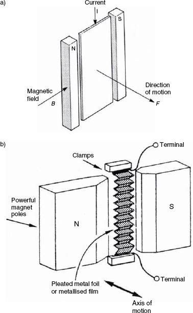
Figure 2.23 The ribbon driver. a) The basic concept of a ribbon driver. The current flowing through the diaphragm reacts with the static magnetic field between the north (N) and south (S) poles, and gives rise to a force, and hence a movement of the diaphragm in the direction shown. b) A more practical realisation
In practice, the ribbon is corrugated to give it more rigidity. In order to avoid giving rise to resonances in its frequency band of operation it is supported at each end but it is not stretched. The support of the ribbon in the gaps is normally by means of elastomers and silicone rubber. As a current flows through the diaphragm, the corresponding magnetic field interacts with the static magnetic field from the magnets parallel to the plane of the ribbon. This generates a force at right angles to the plane of both the magnetic field and the ribbon, which moves the ribbon back and forth, but parallel to the direction of the magnets. To maintain adequate efficiency, the mass and electrical resistance must be kept as low as possible, the latter being typically as low as 0.2 ohms and requiring an impedance matching transformer in order to be useable with normal amplifiers. The low impedances also imply high currents, so a conflict can arise between the thickness of the diaphragm being low enough to keep the weight down but high enough to keep the electrical resistance down, otherwise the diaphragm might melt with the signal current. The classic Decca/Kelly ‘London’ ribbon loudspeaker had a horn attached to it, had a sensitivity of 92 dB SPL for 1 watt at 1 metre distance, and covered a frequency range from 1 to 30 kHz with a power handling of 25 watts. Sonically, it was widely appreciated.
Modern technical advances have led to printed circuit current sheets, with the copper tracks on polyimide sheets of around 12 micrometres thickness. The sheets can be made with overlapping copper tracks on each surface, thus allowing the whole sheet area to be conductive. In conventional ribbons, however, the diaphragm material is usually aluminium, because it has the best compromise between resistance and mass. In recent years, the American company SLS Loudspeakers has made a big feature of the use of ribbon loudspeakers beyond about 2 kHz. Ribbons, traditionally have been delicate, and difficult to manufacture, but sonically they have always had many friends.
2.5 Heil air-motion transformers
These devices often get mistaken for ribbon loudspeakers when people see the folded diaphragms set in short horns, but they are definitely not ribbon loudspeakers. A ribbon radiates sound by the whole diaphragm moving backwards and forwards in a uniform manner, with the pleats never changing their angles. The air-motion transformer, quite differently, moves its diaphragm in a concertina movement, drawing the air into the folds as they expand, and expelling the air as they contract. The German company A.D.A.M Audio have recently featured this technology rather in the way that SLS have made big use of ribbons. The air motion transformer was designed by Dr Oskar Heil and its general outline is shown in Figure 2.24. The current flows through a flat conducting track which is bonded to the diaphragm, and which is folded such that the conductive strip lies parallel to itself on the adjacent fold. When the current flows in one direction through the entire circuit, it travels in different directions in the conductors on adjacent folds, and the magnetic field is either attracted to or repelled from the nearby permanent magnets. When the current in the circuit reverses, the folds which were opened are then closed, and vice versa. It is called an air motion transformer because there is a ratio of about four to one between the air particle velocity in and out of the folds relative to the velocity of movement of the pleated diaphragm. The magnet structures need to be very large because the entire pleated diaphragm must fit in the gap between the poles. The diaphragms are made from plastics such as p.t.f.e. or polyethylene, which have good damping. Current units can work from about 500 Hz to 20 kHz. Some models have been shown to produce quite high levels of second harmonic distortion above about 5 kHz, but the subjective audibility of this does not seem to be significant as the distortion products are all above 10 kHz and about 30 dB down relative to the signal.
2.6 Distributed mode loudspeakers
These are the flat panels developed under licences from NXT and its subsidiary New Transducers Ltd in the UK. The principal patent is held by the British Ministry of Defence, on whose behalf Dr Ken Heron was not actually trying to develop a loudspeaker at all – he was trying to build lighter helicopters and stumbled upon an aluminium honeycomb panel that radiated sound quite efficiently.
At first glance, the concept of a distributed mode loudspeaker (DML) seems to be a total contradiction. It is a mess of resonances, when, in almost all other aspects of loudspeaker design diaphragm, resonances are taboo. The drive points where the electromagnetic exciters couple to the panel are chosen so that they couple to as many of the vibrational modes as possible, in order to excite the panel in the most uniform manner. The panels which are currently used are typically made from resin impregnated glass-fibre sheets bonded to a 3 mm honeycomb core of ‘Nomex’ - a polyamide which is often used to make loudspeaker voice-coil formers. The panels are not driven by a voice coil attached to the panel which is then connected to the same frame/chassis as the magnet, but rather the lightweight panel and coil react against the mass of a much heavier, freely suspended magnet. Panels are commonly excited by two or four coils, to more evenly distribute the drive force. An example of a commercial panel is shown in Figure 2.25.
As the name ‘distributed mode loudspeaker’ suggests, they radiate all frequencies from all parts of the panel, and so are naturally diffuse sources. As such, they can work well in both studios and domestic circumstances as the rear channels of a surround system, where they can create excellent ambient diffusion effects. Their sonic colouration, though not unpleasant, tends to render them inappropriate as main front channels where serious listening is the goal, but their performance on the surround channels can be very involving, and numerous professional installations have used them in this role. It is also interesting to note that the radiation from both sides of the panel (if the rear is not enclosed) couples to the room neither in an omnidirectional way nor as a figure-of-eight pattern (or dipole) like electrostatic panel loudspeakers, but as something more akin to a bi-pole, where the radiation from each side is only partially correlated. As such, and if spaced away from a reflective wall, they can fill a room with reflexions which have very little tendency towards showing typical summation and cancellation effects (peaks and dips in the response) in different places in the room. This characteristic can add still further to the beneficial way that they can be used for ambience channels, where their inherent sonic colouration appears to be little disadvantage.
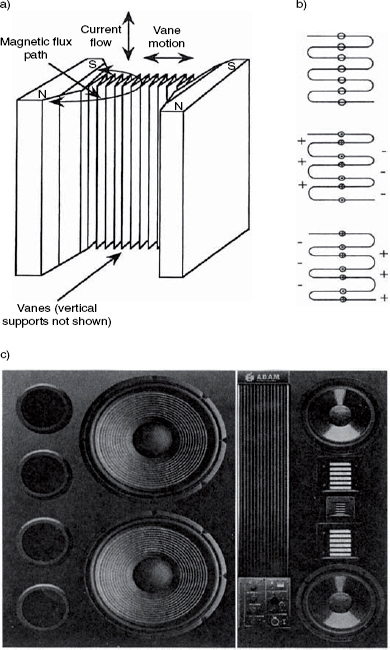
Figure 2.24 The Heil air-motion transformer. a) Perspective view of the basic concept. b) Polarity changes in the conductors cause the opening and closing of alternating folds, drawing in and expelling air on alternate half-cycles. c) A full-range loudspeaker system using Heil air-motion transformers for the mid and high frequencies in a symmetrical, D'Appolito layout – an A.D.A.M. S7
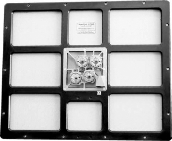
Figure 2.25 A distributed-mode loudspeaker (DML)
A constant problem for DML loudspeakers has been the lack of low frequency output, but designs are now emerging, such as the Fane Minipro, which extend reasonably well down to 60 Hz. For surround use this is often quite adequate, especially since many of these systems will be used with bass management systems which will pass the low frequencies to a separate (sub-) woofer. Panels with dimensions of about 40 cm × 60 cm are sufficient for such purposes, but smaller panels suffer from much higher roll-off frequencies. The low frequency response can be extended by mounting the panels on a shallow, absorbent-lined box, of about 10 cm depth, but care must be taken to avoid over-filling the box with absorbent material or the damping on the rear of the panel can become too great. When the open-backed panels are hung against walls they should be hung at an angle, in order to prevent resonances in the parallel cavity formed between the panels and the wall. As the general radiation directivity is very broad at all frequencies, as shown in Figure 2.26(a), it is not necessary to point the panel at a normal to the listening area. From almost whatever angle a panel is radiating, and no matter where it is in a room, it will excite the whole room with its full frequency range. Only from a position in line with the panel edge is there a region of a few degrees where low frequency cancellation takes place. The high frequencies radiate in an almost omnidirectional manner, though from a spacially diffuse source.
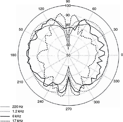
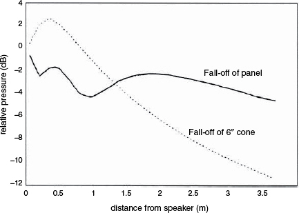
Figure 2.26 Radiation characteristics from a typical DML. a) DML polar response at 220 Hz, 1.2 kHz, 6 kHz and 17 kHz. b) Computed comparison of loudness with distance – a distributed mode panel versus a 6 inch (150 mm) piston. (From data published by NXT)
As a result of the diffuse nature of the radiation, the fall-off of SPL with distance is initially less than from a conventional loudspeaker, as shown in Figure 2.26(b). It is more typical of larger, planar radiators, as discussed in Sections 2.8 and 2.9. This can also be a benefit when filling a room with ambient sounds, because the left and right signals, from positions more or less laterally alongside the listeners, are more evenly distributed across the room, even when the room acoustics are relatively dead. The coupling to the room modes (see Chapter 7 if necessary) is also accomplished in a different manner to the way in which conventional radiators couple with modes. This again has been shown to give rise to fewer peaks and dips in the room. When all the characteristics are taken together, the DMLs do offer some interesting opportunities for surround applications. In fact, the low frequency response can be noticeably better if panels larger than those referred to above are used, but very large flat panels tend to become unwieldy and can introduce resonance and reflexion problems into the room when used in conjunction with other sources.
2.6.1 Panel/piston combinations
Since the mid 1990s, various efforts have been made to develop combinations of DMLs and conventional loudspeakers in such manners as to take advantage of their uncorrelated and correlated radiation characteristics respectively. The thinking behind these ideas is that in live music situations the direct propagation from the instruments to the ears tends to be highly correlated, whilst the reflected energy from walls, ceilings, floors and other hard surfaces tends towards being uncorrelated. In good concert halls it has been found that the ones with low levels of inter-aural cross-correlation tend to produce the generally most desirable sensations of spaciousness. In domestic situations, the reflexions from walls do not tend to be as diffuse and uncorrelated as in good concert halls, and their frequency response is inevitably affected by the directivity characteristics of the loudspeakers. To help to combat these deficiencies, the concept of creating a sensation of diffuse reflexions has been pursued by the use of relatively diffuse sources in combination with a conventional stereo pair of loudspeakers. The relative level of the two types of sources can be adjusted to taste.
The KEF company in the UK has patented a concept of using DMLs behind conventional loudspeakers with the axes of the DMLs at right angles to the axes of the conventional loudspeakers. The conventional loudspeakers generally point towards the listeners, whilst the DMLs work more omnidirectionally (although with their weak lateral nulls towards the listening position) in an attempt to excite the rooms with diffuse reflexions from the surround channel(s) of multichannel recordings.
Another system, marketed under the trade name of Layered Sound, was patented by Dr Shelley Katz, a Canadian pianist, who initially researched the concept as a means to make electric pianos sound less ‘stiff’ and more acoustic. This technology was licensed for research purposes to the Japanese company Korg. In the domestic reproduction or sound reinforcement formats, the panels are placed closely, above or behind the conventional loudspeakers, but usually with the axes parallel to each other, and not necessarily at 90 degrees as with KEF systems. The panels in this system are fed with the same signal as the conventional loudspeakers, and can also fed via a delay, with the delay time and the relative SPLs from the different sources being used to control the overall effect.
By definition, such systems are not high-fidelity in the classical sense, because they seek to introduce artefacts which are not in the original drive signals. Nevertheless, that overall sense of realism which they can help to generate may be considered in many cases to be highly faithful to the sensations of the performance spaces or the wishes of the recording personnel or musicians. Proponents claim that as the current recording processes via conventional microphones and the reproduction via conventional loudspeakers are still limited and compromised by the inherent short-falls of their performance, then piston/panel combinations may be able to realistically add, globally, more than is lost in conventional reproduction, and so can be considered to be more than making up for those short-falls. However, all assessments of these types of loudspeaker systems currently need to be made subjectively, because there are still no measurement systems which can reliably define the performances of such combined systems in any meaningful manner.
Therefore, whilst technical accuracy in terms of conventional reproduction might be compromised, the developers of such combined systems can reasonably claim that the perceptual fidelity, in terms of overall realism, may be superior, at least on certain types of music, to reproduction on systems with more measurable fidelity in the conventional sense. Whilst it would seem to be unwise to use the combined systems for music recording quality monitoring, the beneficial effects of Layered Sound for electric piano amplification seems to be established. Of course, if recordings were being specially made for reproduction on these composite systems or their derivatives, then the monitoring of the recordings via such systems may also be justified. Development of DMLs is still in progress, however, and some new designs are already emerging with much less coloured responses than have previously been achievable.
2.7 Beyond magnetics
All of the loudspeaker drive systems discussed in this chapter so far have been electromagnetic transducers. One way or another, all of them have employed the magnetic field generated by an alternating music signal current in a moveable conductor to react with a static magnetic field. The force generated at right angles to the current and the static magnetic field has then been applied to a diaphragm of some sort or other which has been designed to move air and radiate sound. They are all, basically, variations on the same theme. There are, however, various other means by which loudspeakers can be made.
2.7.1 Piezoelectric devices
There are certain materials which can be made to twist and bend when electrical signals are applied to opposing surfaces, and, in general, there is a useful proportional relationship between the applied voltage and the degree of movement of the material. Such transducers have found use as high frequency loudspeakers of very robust design, which have in turn found use in guitar amplifiers and sound reinforcement systems where conventional tweeters have been considered to be too fragile. Quartz, Rochelle salt and some ceramics such as barium titanate have piezoelectric properties, as do some high polymer plastics, such as polyvinylidene fluoride. Direct radiator and horn loaded piezoelectric radiators are available, the horn-loaded Motorola device being quite widespread and has an axial response within ±3 dB from 4 kHz to 20 kHz. Pioneer have also developed a cylindrical piezo radiator. In these, a thin film of high polymer plastic is made into a cylindrical shape which is then caused to pulsate with the applied signal voltage. The response is respectably flat from 2 kHz to 20 kHz, with 360 horizontal radiation.
The piezoelectric units are rugged largely because they are self-protecting. The impedance tends to rise as the frequency lowers, so driving low frequency signals through them is difficult, even with no crossover. They also, effectively, have nothing to burn out and nothing to go offcentre. Although they are very rarely encountered in loudspeakers used for music monitoring, they can be found in domestic system as well as in music amplification systems. The principles of their construction are shown in Figure 2.27. Piezoelectric drivers tend to be mid-sensitivity devices, offering the low 90s of decibels SPL for one watt (or at least its voltage equivalent – 2.83 volts – into their varying impedance) at one metre distance.
2.7.2 Ionic loudspeakers
It is unlikely that anybody will find these in use today because production ceased around 1968, but the concept is interesting. Radio frequency interference and the production of irritating ozone were unwanted side-effects that helped towards their demise, along with low output, but there is widespread agreement that the sound of these devices was true high fidelity. In ionic drivers a 27 MHz high voltage signal is fed to the electrodes of a quartz cell. A corona discharge results, giving off a blue light as the air is ionised. When the radio frequency voltage is modulated by an applied audio frequency signal the volume of ionised air will vary and produce pressure fluctuations in the air. The frequency response was given as 3 kHz to 50 kHz ± 2 dB, with only 0.5% distortion at 93 dB SPL. Absolute peak output was around 98 dB SPL for the ‘Ionofane’ version. This was the cutting edge of high fidelity in the 1950s and ‘60s, and is still good today, however, at higher SPLs, above about 96 dB at 1 metre, compression soon set in, seriously limiting the output. They also cost 28 guineas each (just under 30 pounds, sterling) in the early 1960s, which was an entire month's salary for many working people in those days.
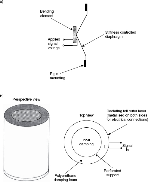
Figure 2.27 Piezo-electric radiators. a) Section view of a typical piezo-electric HF radiator. b) The Pioneer cylindrical piezo-electric driver – the High Polymer Radiator
2.8 Electrostatic loudspeakers
Just as dynamic microphones, such as ribbons and moving coils, have their equivalent loudspeakers, and as piezoelectric loudspeakers relate to crystal microphones, electrostatic loudspeakers are the counterparts to condenser (capacitor) microphones. [Condenser is the old term, capacitor is the modern term, but the old terms often take root.] Within their limitations, electrostatic loudspeakers can produce a sound quality which, in microphone terms, we would only associated with the finest condenser microphones. Sonically they can be astounding. The limitations are size, (because they need large surface areas of diaphragm), relatively low maximum output SPL, and their figure-of-eight radiation pattern which does not suit all room layouts. The typical radiation pattern from a full-range electrostatic loudspeaker (ESL) is shown in Figure 2.28. The absorption of the rear radiation is not a practicable solution unless the box is enormous because the air load would inhibit the movement of the extremely light diaphragm, whose mass is critically chosen to match that of the free air surrounding it. The loudspeakers therefore need to be placed away from walls, and the nature of the walls close to the sides and behind them need to be duly taken into account, acoustically, when the response in front of the loudspeakers is being considered. Full-range electrostatic loudspeakers may therefore be less forgiving in terms of where they can be placed.
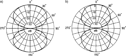
Figure 2.28 Typical directivity pattern from a dipole radiator. a) Low to mid frequency response. b) High frequency response
These devices do not act as volume-velocity pumps like cone loudspeakers, but radiate as pressure gradient sources. This means that they do not couple to the pressure anti-nodes of the room modes, but to the velocity anti-nodes, which are the pressure nodes (see Chapter 7). Other than in anechoic chambers, this means that the optimal siting of electrostatic loudspeakers will be different to that for moving coil loudspeakers. The maximum SPL is limited (although 95 dB SPL should be no problem) because at higher SPLs the polarising voltages would need to be so great that highly specialised materials and techniques would need to be used in the manufacture of the devices, and also because the air would reach its own electrical breakdown limits. This is rather similar to the situation in compression drivers, where the air itself begins to be the limiting factor at higher SPLs. Air is not just something that you can do what you want with. It has its own characteristic properties and it can impose its own limits on what it can be made to do.
The basic concept of an ESL is shown in Figure 2.29. A polarising voltage of around 3000 volts is applied to the diaphragm whilst the two, outer, perforated electrodes, are grounded via resistances, and spaced away by about 2 mm. The charge on the diaphragm keeps it centralised, in equilibrium, in the absence of signal. If, via an input transformer, a signal voltage is applied across the electrodes, the equilibrium point will shift and the diaphragm will move to chase it. The whole device operates on high voltages and high impedances, so the signals have to be fed from the power amplifiers via a step-up transformer, which itself requires careful design if it is to pass all frequencies equally. Nevertheless, this type of loudspeaker is largely a capacitor, so it still presents a predominantly capacitive load to the amplifier, which therefore needs to be able to supply high currents even when voltages are low, due to the phase angle difference between the voltage and the current, (described previously in Section 1.6). The choice of amplifier may therefore depend on its ability to supply current more than its ability to supply power.
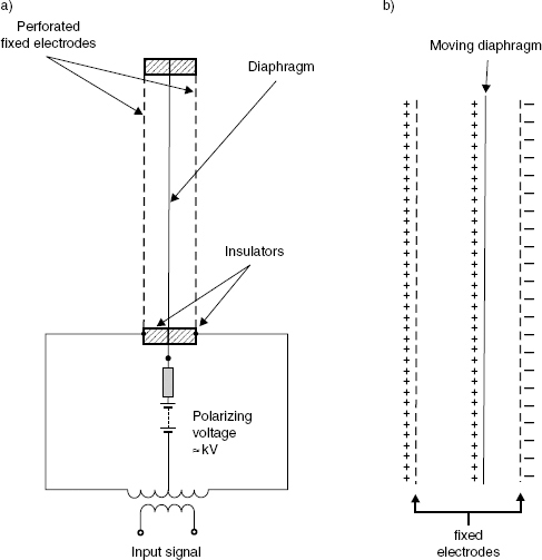
Figure 2.29 The electrostatic radiator. a) The basic principle of operation of an electrostatic loudspeaker. b) When the charge becomes opposite on the fixed electrodes the diaphragm moves to take up a new equilibrium position. If the charge between the fixed electrodes changes, the diaphragm position will change correspondingly
Because of the inevitably small distances between the electrodes, necessary to maintain useful sensitivity with polarising voltages which will not cause air breakdown, the distance that a low frequency diaphragm can travel is severely limited. Therefore, the only way that the diaphragm can move quantities of air sufficient to generate the required SPLs is to be large. However, the diaphragm size of a single unit is limited by its ability to maintain an even tension, and not to sag in places, so this also restricts the SPL achievable by single units.
The large source area would, as with the DML, give a rather irregular directivity at high frequencies, (but without the DMLs ability to produce so many irregularities that they become almost regular again). Full range ESLs therefore tend to be made as two or three-way devices, as with moving coil loudspeakers, using a much smaller radiating area for the higher frequencies. The Quad ESL63 uses a series of concentric rings, as shown in Figure 2.30, in order to mimic a point source situated some way behind the diaphragm. These loudspeakers have also been made available with dipole moving-coil sub-woofers mounted beneath them to extend their rather limited low-frequency responses, or rather, their limited low-frequency output capability due to the limited maximum excursion and size of the diaphragms. Electrostatics are therefore not the ideal loudspeakers for monitoring a solo bass drum in a large control room, but they do find use in critical listening rooms and audiophile high fidelity applications, where their natural sound and resolution of low-level detail are highly valued. When heard in an anechoic room reproducing recordings of acoustic instruments recorded in the same room, and with the instruments alongside for reference, their ability to mimic the original sound can be quite startling. Granted, the anechoic response is not the be-all and end-all of loudspeaker reproduction, but the general tendency is for anything which can work so well in such circumstances to have a good start when transposed to other circumstances. Figure 2.31 shows the step function response of a Quad Electrostatic Loudspeaker: the attack of the signal is exemplary, and very hard to beat with other loudspeakers. [The step function responses are further discussed in Chapter 9.]
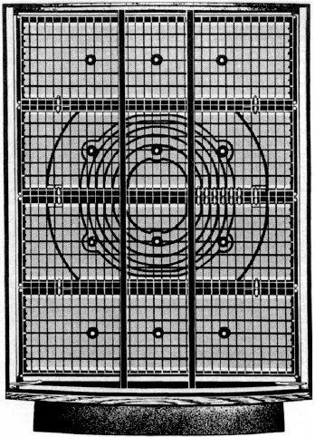
Figure 2.30 The Quad ESL 63 electrostatic loudspeaker with its concentric diaphragms. The higher frequencies radiate only from the central sections
Although the electrostatic loudspeaker principle was experimented with as early as the 1920s, it was not until 1957 that the first really viable design was put into production. It took the advent of the concept of a constant charge and the development of new plastic foils before it could be fully realised. However, once all the pieces of the jig-saw were in place, the progress was remarkable. A pair of ELSs from the 1950s can, even 50 years later, put many of the latest loudspeakers to shame in terms of low colouration, low distortion, transient response, frequency response flatness and, perhaps most of all, perceived sound quality. What Walker and Williamson did when they developed the Quad ESL was to take a step forwards to a degree that has rarely been equalled in the world of sound reproduction, and this is especially so considering all the technical difficulties which they had to overcome.
Whereas the moving coil loudspeaker exhibits non-linearities in its inner suspension, outer suspension, magnetic flux disturbances, magnetic field asymmetries and various other sources, the electrostatics more or less only exhibit non-linearities due to very small asymmetries in construction, which can be minimised by careful quality control. In general, the non-linear distortion production by electrostatic loudspeakers is much lower than that produced by most moving coil devices. The authors of this book have, for decades, used full-range electrostatic loudspeakers as benchmarks against which to judge other loudspeakers, both objectively and subjectively. This is not to say that they cannot be surpassed on individual aspects of their performance, but their global performance is hard to beat.
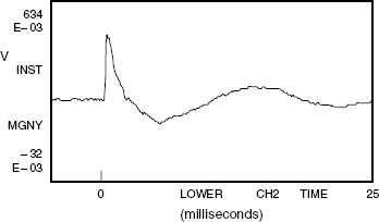
Figure 2.31 Step function response of an electrostatic loudspeaker, showing the exemplary attack (rise time)
Occasionally, electrostatic mid-range drivers and/or high frequency drivers can also be found in compound, electromagnetic/electrostatic designs of domestic loudspeaker systems.
2.9 Electromagnetic planar loudspeakers
As if to rise to the electrostatic challenge, one of the electro-dynamic (electromagnetic) responses was the planar loudspeaker. These use light, thin, tensioned plastic film diaphragms which have voice coil circuits printed on them, rather in the manner of a very thin printed circuit board. The diaphragms are stretched over frames with many openings and a large number of small magnets dispersed over their area. There is no attempt to concentrate the flux in any area, but just to set up a field of fringe flux in the vicinity of the magnets. In this way, a diaphragm is caused to move by the reaction of the signal current in the printed tracks with the static magnetic field, which results in the diaphragm being more or less uniformly driven over its entire surface. As with large electrostatic diaphragms, they must cross over at higher frequencies into drivers of smaller radiating area if strange directivity problems are to be avoided. They do not have the ‘random’ distribution of high frequency sources as exhibited by the DMLs, but neither do they tend to have as much colouration.
2.10 Summary
There are a considerable number of different ways to transform electrical drive signals into sound waves, and no one system has all of the advantages to itself. In fact, all the drive systems are electro-mechanico-acoustic transducers; that is, they must first convert the electrical signals into mechanical forces which are then used to drive sound radiating diaphragms of some sort or another. (The one exception perhaps, being the now defunct ionic tweeter.) The necessary double conversion tends to involve a number of non-linear processes, and it is largely the mechanical components which are the main offenders. It is therefore unfortunate that we often refer to loudspeakers as simply electro-acoustic transducers because it fails to recognise the existence of the principal culprit for our problems.
At the limit, the air itself is non-linear, so when we try to reproduce loud sounds from small sources that were originally produced by large sources, local concentrations of high air pressures close to the small sources will give rise to non-linearities, which our ears will recognise as not being the real thing. The reason for describing this wide range of loudspeaker drive unit concepts so early in the book (and there are other, less common ones) is to establish the point that at the very heart of all loudspeaker systems are imperfect components, and, as mentioned earlier, that the art of the science of the designs is to find the best compromise for any individual requirement.
References
1 Colloms, M., ‘High Performance Loudspeakers’, 5th Edition, John Wiley & Sons, Chichester, UK (1997)
2 Briggs, G., ‘Loudspeakers, The Why and How of Good Reproduction’, Fourth Edition, Wharfedale Wireless Works Ltd, Bradford, UK (1955)
3 Borwick, J., ‘Loudspeaker and Headphone Handbook’ Second Edition, Chapter 2 (By Stanley Kelly), Focal Press, Oxford, UK (1994)
Bibliography
1 Chapter 3 of Reference 3, above, contains what is perhaps the definitive work on electrostatic loudspeakers, written by the late Peter Baxandall. In the Third Edition of the book, published in 2001, Peter Walker somewhat modified the text. Either edition, in its entirety, is recommended reading for anybody wishing to delve deeper into the world of loudspeakers and headphones.
2 The books mentioned in References 1 and 3 above
3 Eargle, J., ‘Loudspeaker Handbook’, Chapman and Hall, New York, USA and London, UK (1997)
4 Borwick, J., ‘Loudspeaker and Headphone Handbook’, Third Edition, Focal Press, Oxford, UK (2001)