
Chapter 3
Loudspeaker cabinets
3.1 The concept of the infinite baffle
When the diaphragm of an open-framed driver moves forwards, the compression of the air at the face of the diaphragm is accompanied by a rarefaction at the other side of the diaphragm, and the natural tendency is for the pressure difference to equalise itself by a movement of air around the sides of the driver. At frequencies whose wavelengths are large compared to the circumference of the diaphragm, the equalisation is almost perfectly accomplished, and so almost no sound is radiated. It is therefore necessary to discourage this pressure equalisation if low frequencies are to be radiated. The simplest means of accomplishing this is to mount the loudspeaker in a large, rigid board, or baffle, as shown in Figure 3.1. If the board were to extend in all directions to infinity, it would be a true infinite baffle. It would cause no change in the air loading on each side of the diaphragm, it would exhibit no resonances, it could cause no diffraction, and, with a good quality driver (or drivers) would sound excellent. Unfortunately, its great drawback is that it is a rather impractical concept.
The two practical realisations of this idea are the finite baffle, where a baffle of perhaps a metre square is employed, or the so-called infinite baffle, which is, in fact, a sealed box. The radiation pattern of the finite baffle is shown in Figure 3.2(a). The cancellation around the sides of the extended plane of the driver cause response nulls to the sides, in the direction of the plane of the baffle, resulting in a three-dimensional figure-of-eight pattern in free space. The low frequency cut-off is determined by the size of the baffle. The final rate of low frequency roll-off is 18 dB per octave, but some measures can affect the nature of the entry to the roll-off. Varying the Q of the driver resonance, by mechanical and/or magnetic changes, can yield response shapes such as those shown in Figure 3.2(b). By placing the driver off-centre, the cut-off can be made more gradual due to the distance from the driver to each edge of the baffle being different. Open baffles are rarely used in recording studio control rooms because of the problems of where to site them and how to control the rear radiation, but they find use in listening rooms and domestic high-fidelity systems. In these instances the baffles can be sited somewhat more flexibly than in an equipment-loaded control room, and the loudspeaker and listener positions can usually be found which give good results. Subjectively, open baffles tend to sound very clean and, not surprisingly, open. They are largely free of resonances, so their time-domain responses are limited only by the drivers and the rooms in which they are placed. The ways in which they couple to the rooms will be discussed in Chapter 7.
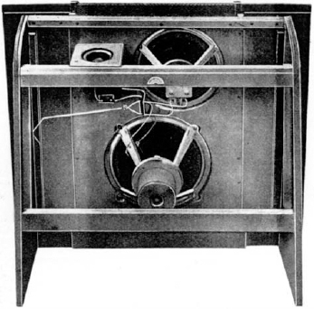
Figure 3.1 An open baffle of Wharfedale design from the 1950s. The front panel was a sand-filled plywood sandwich, to damp resonances. The upward-pointing tweeter was to generate a more diffuse high-frequency response
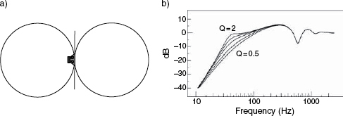
Figure 3.2 Directivity and roll-off of open baffles. a) Radiation pattern polar plot of an open, finite baffle. b) Low frequency response roll-off of an open baffle, showing the effect of the Q (degree of sharpness of resonance) of the driver. The final roll-off tends towards 18 dB per octave below the driver resonance
When mounted on the floor, the solid surface below the open baffle acts like an acoustic mirror, so a baffle of one square metre placed on the floor behaves like a baffle of two square metres in free space. This enables baffles of practical size to be useful down to frequencies of 40 Hz or below, but the lack of anything other than atmospheric loading on the rear of the diaphragms and poor efficiency of radiation may lead to over-excursion problems with high sound pressure levels at low frequencies. The resonance frequency of the driver on an open baffle will be that of its free-air resonance. Because the open baffle mounting does not push up the free air resonance of the driver, and the back-pressures are not augmented by any constraint of the air behind the diaphragm, lighter moving assemblies may be used. Driver cooling is also something that poses no problem with open baffles, so power compression problems are rarely encountered. The open baffle, in the hi-fi world, still enjoys a devoted following of aficionados.
3.2 The sealed box
The practical realisation of an infinite baffle (the sealed box) is rarely large enough to avoid significantly loading the rear of the loudspeaker, so is best called what it really is, a sealed box. Just as open baffles tend to sound ‘open’, sealed boxes often tend to sound ‘boxy’. However, this need not be the case if the box and driver are of adequate size, well-matched, and if sufficient attention is paid to the suppression of resonances within the box. The constraint of the air within a sealed box causes it to act like a spring, which reacts against the movement of the diaphragm in either direction. This effectively stiffens the suspension of the drive unit, and raises its resonant frequency. The smaller the box, the stiffer will be the spring, so the higher will be the resonant frequency of the driver/box system. As the system resonance defines the frequency at which the low frequency roll-off will begin, then for any given driver the low frequency response will become progressively more curtailed as the box size reduces. The only way to counteract this tendency is to use drivers of lower free-air resonance frequency, which means using a driver with a heavier moving assembly or, to a lesser extent, a more compliant suspension, but both of these characteristics have their drawbacks.
A heavier cone takes more energy to move it, so it will need more amplifier power to drive it to produce the same SPL as a lighter cone. A more compliant suspension will be much less rugged than a stiffer suspension, and will tend to be much more easily damaged in the event of an overload. What is more, a very loose, flexible suspension may not be able to adequately resist the pressure changes inside the box at high SPLs, and may physically deform, giving rise to non-linearities in its travel and non-linear distortions in its radiation. This will all be discussed in much more detail in Chapter 11, but suffice it to say here that a small sealed box must suffer from either poor system sensitivity (due to its poor, overall electro-acoustic conversion efficiency) or a low frequency roll-off that begins well into the musical spectrum. The roll-off exhibits a rate of 12 dB per octave below its frequency of resonance, but considerable roll-off may begin well above this frequency, depending on the system
Q. Some typical roll-off curves are shown in Figure 3.3. Nevertheless, the time responses (transient responses) of well-designed sealed boxes with correctly matched drivers and adequate damping can be very accurate. Largely for this reason, sealed boxes have a strong following, and large sealed boxes can be the bases of excellent loudspeaker systems.
A sealed box system is said to be critically damped when its size and the driver resonant frequency are matched such that the overall response is already 6 dB down at the resonant frequency. With this alignment, the transient response can be exemplary, with no perceptible ringing. The total system QTC (or quality factor of resonance) is 0.5. The Butterworth ‘B2’ (maximally flat) alignment is very popular, with a QTC of 0.7. This exhibits a system response which is 3 dB down at the resonant frequency, and still has a transient response which is extremely well controlled. The low frequency responses can be extended downwards with alignments where the QTC is set at 1, or even up to 2, but as the Q increases, so does the tendency for the transient response to become extended, and for audible ringing or ‘boominess’ to become obtrusive. The outcome of these relationships is that if the low frequency −3 dB point is to be dropped to 30 Hz, and a fast, well-damped transient response is required at the same time, then the box must be big. If high SPLs are required, then the only solution to the compromise of a low resonance driver with an adequately robust construction and a good sensitivity is that the driver must also be big.
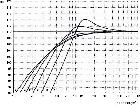
Figure 3.3 Typical low frequency roll-off behaviour of a sealed box loudspeaker, showing the responses of the same driver in cabinets of six different volumes. All measurements in free-field conditions
A, 7L. B, 14L. C, 28L. D, 56L. E, 112L. F, 224L
Loudspeaker free-air resonance 20 Hz
A 15 inch (380 mm) driver, of high quality, with a 20 Hz free air resonance in a 500 litre enclosure can yield some very impressive bass. However, ‘impressive’ in this context means full, flat, fast and low distortion – in other words, ‘accurate’. Unfortunately, many sealed boxes get themselves a bad name by trying to use ‘boomy’ alignments in forlorn efforts to keep the size down whilst seeking to extend the low frequency response to frequencies that the box size cannot really support. The penalty paid is in terms of low sensitivity and poor transient response. It must be thoroughly understood that there is no clever computer program which can solve this problem. The restrictions that we must accept are deeply entrenched in the physical laws of the universe in which we live. They are that fundamental!
Some manufacturers have tried to sacrifice system sensitivity by lowering the magnet flux in order to lower the system Q. There is a strong ‘amplifier power in cheap’ lobby, who believe that lower efficiency systems can exhibit higher Qs, and hence can be extended in their low frequency range. What they often seem to fail to realise is that a heavier current in the voice coil and a lower power magnet will drastically alter the ratio of the fixed magnetic field to the variable magnet field. The much higher variable field due to the voice coil current can severely distort the position of the flux lines of the weak, permanent magnet, and give rise to loss of low level detail in the sound and increased levels of intermodulation distortion. This highlights perhaps one of the worse aspects of the use of programmable calculators or computers in the wrong hands – they can lead to good results on paper, but they can give rise to unpleasant side-effects in practice. Figure 3.4 gives a graphic illustration of the connection between system Q (QTC) and the transient response. The QTC is derived from the electrical, magnetic, mechanical and acoustical properties of the total system – electro magnetic damping, mechanical stiffness and air loading. Note that as the QTC increases, the transient response becomes longer. This is perfectly logical because the transient response becomes more resonant as the system QTC becomes more resonant. The amplitude response is boosted and extended downwards by keeping the energy responding for a longer time, and not by instantaneously boosting the level. As stated before, in order to boost the level, and nothing else, a bigger box and driver are needed.
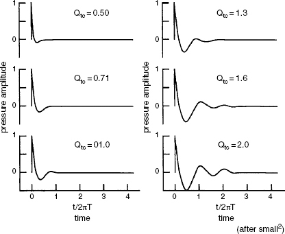
Figure 3.4 Transient response of a sealed box enclosure as a function of the total system Q (QTC). As the QTC increases, the transient decay time also increases
Small sealed boxes with relatively high rates of roll-off can be mounted near to room boundaries, where the constraint of their radiation angle can boost their low frequency output, acoustically, without suffering time penalties (boundary effects are discussed in Chapter 7), but on pedestals in the centre of a room, the low frequencies from small sealed boxes will be found to be either weak, resonant or both. On the metre bridge of a solidly-built mixing console they can also receive some low frequency support, but colouration problems due to the reflective surface being between the small loudspeaker and the listening position can be a problem. This ‘acoustic mirror’ concept was discussed in the previous section, but when applied to floor standing open baffles, the mid and high frequency drive units are usually mounted well clear of the floor. When a small sealed box is placed on top of a mixing console, the sources of mid-range and high frequencies are inevitably close to the reflecting surface, so comb-filtering of the response is the likely result.
To put things into proportion with respect to size, a cabinet which is 3 dB down with a given low frequency driver at 80 Hz would need to be 4 times larger if it were to be 3 dB down at 40 Hz and 16 times larger to be 3 dB down at 20 Hz, so sealed box sizes do tend to get larger very quickly if lower roll-of frequencies are required.
One advantage of sealed box systems is that they are relatively self-protecting in terms of excessive cone excursions. Compared to the open baffle, which offers almost no protection, an input signal below the resonant frequency of a sealed box system will tend to drive the cone at a constant excursion for any given input level, independent of frequency. (See Note 1 at end of chapter.) The thermal overload of the coil is therefore the biggest risk factor in terms of driver integrity at input level extremes.
The lining materials in the boxes also have an effect on the low frequency response. Although they are primarily intended to prevent cabinet resonances at mid frequencies, which may colour the sound by passing to the outside via a relatively acoustically transparent cone, the lining materials can also affect the low frequency damping and total system Q. They should not be too tightly packed, or effectively they will be more or less solid and will reduce the enclosure volume. Neither should they be able to move en masse, or they can introduce non-linear distortion due to their somewhat erratic movement. Given just the right quantity, however, they can not only reduce box resonances but can also make the boxes appear to be up to around 20% acoustically bigger due to their ability to act as heat sinks and slow down the speed of sound by absorbing heat on compression half cycles and releasing it on rarefaction half cycles. The tortuosity of the path through the pores or fibres also gives rise to sound absorption. The density and quantity of the absorbent material inside a sealed box are therefore chosen for the parts that they play in the air loading and damping calculations for the whole system.
3.2.1 Acoustic suspensions
Developed in the 1950s by Edgar Villchur, in the USA. The principal is to use a very low resonance loudspeaker in a small sealed box. The air in the box may push up the resonance by an octave, or more, and is the predominant restoring force for centralising the diaphragm, because the low resonance suspension is very weak. Generally, although an acoustic suspension system is a sealed box, the specialised term is normally only used when the ratio of the cabinet (air) compliance to the driver's compliance exceeds a factor of about 4 to 11. In the late ‘50s and early ‘60s, the company Acoustic Research enjoyed very great success with these designs by making huge improvements in the low frequency fidelity of small loudspeaker systems.
3.3 Reflex enclosures
Also known as ported enclosures, vented boxes or phase inverters, reflex enclosures use openings, or ports, to tune the cabinet resonance to a desired frequency. Effectively, the air in the port, which may be a simple hole or a tube, acts as a mass which resonates with the spring created by the air inside the cabinet. In Figure 3.5, a mass is shown suspended below a spring. Almost everybody will intuitively know what would happen if they were to pull down on the weight and then let go – the weight would spring back and the system would go into oscillation until the energy was finally dissipated. Adding more weight would cause the oscillation to slow down, as would using a weaker spring. Therefore:
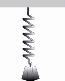
Figure 3.5 A mass/spring system. A mass suspended beneath a spring. It is easy to imagine how pulling down on the weight and releasing it would set up an oscillation due to the mass-spring interaction
In the case of a reflex cabinet, a bigger box provides a weaker spring, because the enclosed air is compressed or rarefied proportionately less than in a small box for any given diaphragm displacement. For any given diameter of hole (port), extending it with a tube will lower the resonant frequency because a greater mass of air will be trapped within it. For any given cabinet volume and mass of air in the port, changing the area of the port will also change the resonant frequency. Increasing the area will increase the resonant frequency. This is because there is more surface area in contact with the air-spring, so more force acts upon the air mass, effectively stiffening the spring. There are therefore three variables in the equation, the cabinet volume, the length of the port, and the area of the port – the latter two defining the volume of air in the port, and hence its mass. Air weighs about 1.2 kg per cubic metre, and thus about 1.2 grams per litre.
The cabinet tuning frequency can therefore be calculated approximately from either of the two following equations, the first in imperial measure and the second in metric units.
![]()
where:
| fv | = | resonant frequency of box (Hz) |
| A | = | area of port in square inches |
| V | = | volume of box in cubic feet |
| L | = | length of port in inches |
OR
![]()
where:
| f | = | resonant frequency of box (Hz) |
| c | = | speed of sound in air − 340 m/s |
| A | = | area of port in square metres |
| V | = | volume of box in cubic metres |
| Le | = | effective length of port in metres |
Note: Le allows for an end correction. The effective length of a port tube is, in reality, somewhat longer than the physical length, but for many calculations the actual, physical length can be used.
The formulae are not precise, because there are always variables such as the quantity of air displaced by the drive units themselves, the air displaced by the port tubes, the air displaced by internal bracing, and the effect of the absorbent material inside the enclosure. Nevertheless, the formulae give good working approximations or starting points for calculations. Of course, the cabinet volume is calculated from the interior dimensions of the cabinet, not the exterior dimensions.
In practice, when the frequency of resonance of the driver in the cabinet is just above the resonant frequency of the box, the port resonance gives rise to a high load on the diaphragm and greatly reduces the diaphragm excursion. In this way, the ported cabinet can protect the driver from excessive travel while still maintaining a flat response. Below this frequency, the driver output falls, but the port, itself, begins to radiate, thus extending downwards the frequency response. At still lower frequencies the port and loudspeaker outputs occur in opposite polarity, so the response falls off rapidly at 24 dB per octave. Moreover, below the port resonance, air simply pumps in and out of the port under the influence of the driver. At these frequencies, the cabinet is just a box with a big air leak, and it can provide no loading on the driver diaphragm, which then behaves as if it were in an open baffle with no air loading protection, so over-excursions are easy to encounter in reflex enclosures unless the low frequency drive signal is filtered, or has no natural content, below the resonant frequency of the box.
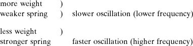
A comparison of the performance of two different low frequency drivers in an open baffle, a sealed box, and a reflex enclosure is shown in Figure 3.6. In practice, a driver would be specifically designed for each type of loading, because the different cabinets or baffles match more optimally with drivers of specific QTC values. The QTS, which can be found in many formulae and reference texts, is the sum of the QMS and the QES , which are the mechanical and electrical system quality factors (sharpness of resonance), respectively. The higher the Q, in each case, the more highly tuned is the resonance, as shown in Figure 3.7. For reference, the Q terms commonly found in loudspeaker texts are as follows2:
QMS is the mechanical system Q. It is the ratio of the electrical equivalent of the frictional resistance of the moving parts of the driver to the reflected motional reactance at the free-air resonance frequency of the driver.
QES is the electrical system Q, which is given by the ratio of the voice coil DC resistance to the reflected motional reactance at the free-air resonance frequency of the driver.
QTS is the parallel combination of the QMS and QES, and the equation takes the same form as that for two, parallel, electrical resistors:
![]()
QTC is the total system Q of the driver and the cabinet.
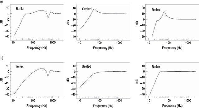
Figure 3.6 a) Response of one driver mounted in an open baffle, a 50L sealed box, and a 50L reflex enclosure with the driver Q optimised for the open baffle response. b) As in a), but with the driver Q optimised for the reflex enclosure. Note how as the driver is optimised for one type of loading, the response may suffer with other types of loading
Figure 3.7 a) Transient response of a reflex enclosure as a function of the total system Q (QTC). Compare with Figure 3.4. b) Pressure amplitude response of the C4 and B4 alignments. Note how the response extension of the C4 alignment corresponds with an increase in the decay time, as shown in a). Transient response is traded for response extension
The free-air resonant frequency of the drivers for reflex enclosures may also need to be different to the optimum resonant frequencies for sealed enclosures of similar size or covering a similar frequency range. The modern tendency is to tailor complete driver designs to given box sizes and system concepts, and the programs now available for computer analysis are very powerful and very accurate. However, careful listening tests are still a sine qua non because concentration on the optimisation of one aspect of driver design may unexpectedly change for the worse some other aspect of performance that was not under such close scrutiny. Unfortunately, listening rooms are expensive to build and listening panels can be an expensive luxury. Computer time on the other hand is cheap, and quick, and there has developed a strong tendency to design systems ever more by computer and ever less by careful listening.
3.4 Acoustic labyrinths
These are sometimes referred to as transmission lines, but at low frequencies they are usually not transmission lines. A true transmission line needs a rear cavity, straight or folded, at least a quarter of a wavelength long. At 30 Hz, with a wavelength of about 11 metres, the line would need to be around 3 metres long, and lines of this length are rare indeed. A true transmission line works by presenting the correct acoustic impedance at the rear of a driver so that all the backwards radiation propagates away from the driver, never to return. This can be achieved by loading the rear of the driver with an infinitely long pipe (which is rather impractical) or by some other system that absorbs all the sound energy. A finite length pipe can therefore be made to operate as a transmission line if it contains sound absorbing material strategically placed to give the correct, purely resistive acoustic impedance, such as an anechoic wedge. However, in order to work at low frequencies this pipe still needs to be very long, so some form of low frequency tuning is often employed.
If, instead of an infinite pipe we think of an organ pipe, it would exhibit a series of resonant frequencies determined by its length. If we attach it to the rear of the driver and fold it round to the front, there will be interference between the sound from the front of the driver and that from the open end of the pipe. When the pipe is one quarter wavelength long, there will be a high acoustic pressure at the rear of the driver and a high acoustic velocity at the open end, which combines with a phase difference of 90 degrees with the acoustic velocity from the front of the driver, and this provides a useful boost in output. As the frequency is lowered, the output from the pipe increases in phase difference with respect to the direct output from the driver, and so tends towards cancelling the combined output. This yields a 24 dB per octave roll-off below the tuning frequency, which leads to transient problems not unlike those of a conventional reflex cabinet. A finite length open pipe, which is what the vast majority of so-called transmission lines certainly are, is clearly not a transmission line, as it works on a completely different principle and yields a different acoustic performance. A typical cross-section of such a design is shown in Figure 3.8(a).
In order to tame the strong resonant behaviour exhibited by the open pipe, absorbent material is introduced into the pipe to add damping. As the amount of absorbent material is increased, the acoustic performance tends towards that of a transmission line except at very low frequencies, where there is insufficient absorption. A carefully lined, or filled, open-ended pipe may thus exhibit some of the properties of a transmission line, but may also rely on the quarter wavelength resonance to supplement the total low frequency sound output. Most commercial ‘transmission lines’ are therefore really something between the two extremes of a transmission line and an open pipe, depending on the amount of absorption present at any given frequency.
Some versions of ‘transmission lines’ are closed. In these designs the line is made to be as absorbent as possible. In reality it is a sealed box, but it differs from the sealed box in that there is no added air-spring effect, and therefore it does not raise the free-air resonance of the driver.
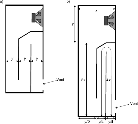
Figure 3.8 Acoustic labyrinths. a) A parallel labyrinth. b) A tapered labyrinth – each time the section of the labyrinth changes, the length (x doubles and the width (y) halves. The entire labyrinth would be lined with absorbent material in both a) and b)
In practice, the low frequency ‘pipe’, whether straight or folded, must not only be a quarter wavelength long at the lowest frequencies, but must also be wide enough so as not to obstruct the rear radiation from the driver. In some cabinets, as shown in Figure 3.8(b), the line narrows along its length, each section doubling the length of the previous section and halving its cross-section. Inevitably, in order to maintain close to ideal working, transmission line enclosures need to be large, therefore a small, low frequency transmission line tends to be a contradiction in terms. The smaller cabinets at low frequencies may act as either sealed boxes or reflex enclosures, dependent upon the density and distribution of the absorbent material. The labyrinth enclosures with open-end terminations tend to act like reflex enclosures in that the cone excursions are much reduced at the resonant frequency of the enclosure tuning, which may result in lower distortion than might be expected from an approximately equivalent sealed box at similar SPLs.
One other interesting aspect of acoustic labyrinths is that the highly resistive rear loading can actually lower the driver's free-air resonance due to the mass of air which acts directly on the cone, effectively making it heavier when in movement.
Labyrinths/transmission-lines have their following, but many designers feel that they are a complex way of achieving rather little. In lines which almost totally lose the rear radiation, there is no out of phase output at low frequencies, so they exhibit 12 dB per octave roll-offs like sealed boxes.
3.4.1 Modern transmission lines
In the early 1990s, the British company PMC (Professional Monitor Company) began manufacturing a range of ‘transmission line’ loudspeakers which have since achieved considerable acclaim and commercial success. The subject of what is and what is not a transmission line has been rather controversial in recent years, so Peter Thomas, the principal design engineer and managing director was asked by the authors of this book to try to clarify the matter, and he subsequently supplied the following paragraphs of this section.
The birth of the modern transmission line speaker design came about in 1965 with the publication of A R Bailey's article in Wireless World, “A Non-resonant Loudspeaker Enclosure Design”3, detailing a working transmission line. Radford Audio took up this innovative design and briefly manufactured the first commercial transmission line loudspeaker. Shortly thereafter John Wright of IMF Electronics designed a range of transmission line designs and made them popular through his refinement and development of Bailey's theory. Although acknowledged as the father of the transmission line, Bailey's work drew on the work on labyrinth design, dating back as early as the 1930s. His design, however, differed significantly in the way in which he filled the cabinet with absorbent materials. Bailey hit upon the idea of absorbing all the energy generated by the bass unit inside the cabinet, providing an inert platform for the drive unit to work from. Unchecked, this energy produces spurious resonances in the cabinet and its structure, adding distortion to the original signal.
The transmission line (TL) is the theoretical ideal and most complex construction with which to load a moving coil drive unit. The most practical implementation is to fit a drive unit to the end of a long duct that is open ended. In practice, the duct is folded inside a conventional shaped cabinet with the open end of the duct usually appearing as a vent on the front of the cabinet. There are many ways in which the duct can be folded, and Figure 3.8 illustrates two typical forms. The line is often tapered in cross-section to avoid parallel internal surfaces that encourage standing waves. Depending upon the drive unit and quantity – and various physical properties – of absorbent material, the amount of taper will be adjusted during the design process to tune the duct to remove irregularities in its response. The internal partitioning provides substantial bracing for the entire structure, reducing cabinet flexing and colouration. The inside faces of the duct or line are treated with an absorbent material to provide the correct termination with frequency to load the drive unit as a TL. A theoretically perfect TL would absorb all frequencies entering the line from the rear of the drive unit, but remains theoretical as it would have to be infinitely long. The physical constraints of the real world demand that the length of the line must often be less than 4 meters before the cabinet becomes too large for any practical applications, so not all the rear energy can be absorbed by the line. In a realised TL, only the upper bass is TL loaded in the true sense of the term (i.e. fully absorbed); the low bass is allowed to freely radiate from the vent in the cabinet. The line therefore effectively works as a low pass filter, another crossover point in fact, achieved acoustically by the line and its absorbent filling. Below this ‘crossover point’ the low bass is loaded by the column of air formed by the length of the line. The length is specified to reverse the phase of the rear output of the drive unit as it exits the vent. This energy combines with the output of the bass unit, extending its response and effectively creating a second driver.
Phase inversion is achieved by selecting a length of line that is equal to the quarter wavelength of the target lowest frequency. The effect is illustrated in Figure 3.9(a), which shows a hard boundary at one end (the speaker) and the open-ended line vent at the other. The phase relationship between the bass driver and vent is in phase in the pass band until the frequency approaches the quarter wavelength, when the relationship reaches 90 degrees as shown. However by this time the vent is producing most of the output – as shown in Figure 3.9(b). Because the line is operating over several octaves with the drive unit, cone excursion is reduced, providing higher SPL's and lower distortion levels compared with reflex and sealed box designs.
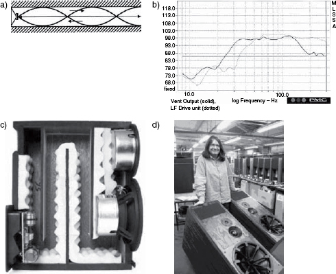
Figure 3.9 PMC transmission lines. a) Phase relationship between the driver and the vent in the quarter wave transmission line. b) The drive unit and vent contributions to the overall output. c) Cut-away view of a PMC transmission line. d) A pair of large PMC cabinets, with their designer
The calculation of the length of the line required for a certain bass extension appears to be straightforward, based on a simple formula:
![]()
where:
f is the quarter wavelength frequency
344 ms is the speed of sound in air at 20 degrees C
λ is the length of the transmission line
However the introduction of the absorption materials reduces the velocity of sound through the line, as discovered by Bailey in his original work. Bradbury published his extensive tests to determine this effect in an AES Journal in 19764 and his results agreed that heavily damped lines could reduce the velocity of sound by as much as 50%, although 35% is typical in medium damped lines. Bradbury's tests were carried out using fibrous materials, typically longhaired wool and glass fibre. These kinds of materials however produce highly variable effects that are not consistently repeatable for production purposes. They are also liable to produce inconsistencies due to movement, climatic factors and effects over time. High specification acoustic foams, developed by PMC with similar characteristics to longhaired wool, provide repeatable results for consistent production. The density of the polymer, the diameter of the pores and the sculptured profiling are all specified to provide the correct absorption for each speaker model. Quantity and position of the foam is critical to engineer a low pass acoustic filter that provides adequate attenuation of the upper bass frequencies, whilst allowing an unimpeded path for the low bass frequencies.
There are therefore two distinct forms of bass loading employed in a TL, which historically and confusingly have been amalgamated in the TL description. Separating the upper and lower bass analysis reveals why the TL has so many advantages over reflex and sealed box designs. The upper bass is almost completely absorbed by the line allowing a clean and neutral response. The lower bass is extended effortlessly and distortion is lowered by the line's control over the drive unit's excursion. One great advantage of the low frequency extension provided by transmission lines is the perception of deep bass even at low listening levels, due to the extended flatness of the response.
The complex loading of the bass drive unit demands specific Thiele-Small driver parameters to realise the full benefits of a TL design. Most drive units in the marketplace are developed for the more common reflex and sealed box designs and are usually not suitable for TL loading. To design a high efficiency woofer with extended low frequency ability, one tends to need cones which are often extremely light and flexible with very compliant suspensions. Whilst performing well in a reflex design, these characteristics do not match the demands of a TL design. The drive unit is effectively coupled to a long column of air which has mass. This lowers the resonant frequency of the drive unit, negating the need for a highly compliant device. Furthermore, the control of this column of air requires an extremely rigid cone, to avoid deformation and consequent distortion. The lack of available suitable drive units created the necessity for PMC to design a series of drivers employing a flat, 6mm thick diaphragm, manufactured from aerospace materials, that provide extraordinary stiffness whilst maintaining a relatively low mass.
The combination of extended frequency response, higher sound pressure levels and lower distortion afforded by TLs, separates them from reflex and sealed box models. In addition, phase accuracy is superior to many other moving coil designs as a result of the absorption provided by the line in the upper bass range. The low frequency roll off can be as low as 12 dB per octave in highly damped lines, matching the sealed box arrangement and avoiding the large phase changes inherent in reflex designs. A cut-away section of a PMC transmission line is shown in Figure 3.9(c), and a pair of complete cabinets in Figure 3.9(d).
3.5 ABR systems
A variation on the use of reflex enclosures is to use an auxiliary bass radiator (ABR) instead of a port. The ABR often takes the form of a loudspeaker with no magnet assembly. They are often also referred to as passive radiators or drone cones, and are normally of approximately the same size as the cone of the driver. One of the primary advantages of ABRs is that there is no air-flow associated with them, so there is no turbulence or wind noise, which can be a problem when small diameter ports are the only means of tuning a cabinet. On the negative side, the compliance (springiness) of the suspension system of an ABR can be nonlinear at high excursions, and hence can be a source of distortion which can be more subjectively noticeable than port distortion.
ABRs can be used in small boxes, giving them a reflex-type response when the tuning frequency would require ports which would be too small to be practical. In general, ABRs offer reflex-type advantages over sealed boxes, such as 4–6 dB more output on typical programme material and a lower −3 dB point at low frequencies, but the cut-off is more steep once it begins, and, as with any resonant system, the transient response gets smeared. The transient response of a resonant system depends upon the Q of the resonance, as shown in Figure 3.7. There are some alignments (tunings) known as quasi-Butterworth third order (QB3) and sub-Chebychev fourth order (SC4) which use lower Qs. They exhibit transient characteristics rather like sealed boxes of Q = 1 (see Figure 3.4) but maintain the reduced diaphragm excursions of the reflex enclosures. However, the choice of musical programme and room acoustics may well be the determining factor as to whether these alignments are beneficial or not. Electronic music in a highly damped control room is much more revealing of tuning resonances than would be romantic music in a relatively live domestic room. In many ways it is fortunate that we have at our disposal a range of loudspeaker performances, because none are perfect, and we have a similar range of musical and acoustical requirements.
ABR systems have not had a totally continuous development. They tend to emerge from time to time as solutions to specific problems. When air is used in a resonator, its density is fixed, so if not enough volume is available in the cabinet for the necessary sized port, or if excessively long tubes are called for (which suffer from viscous losses), then low tuning frequencies cannot be accomplished. An ABR offers the use of a number of different materials of varying weights (masses, densities) and also offers the possibilities of lower box tuning when size is limited. Polystyrene diaphragms of the correct weight, suspended in a loudspeaker-type surround (usually a half-roll) are now often the choice of the designers who use ABRs, as shown in Figure 3.10(a). The total acoustic output is the sum of the volume velocity of the front of the driver diaphragm and the out of phase volume velocity of the ABR. The ABR is, of course, driven by the rear of the driver via the air in the cabinet. The relative contributions of the driver and the ABR to the combined output of the system is shown in Figure 3.10(b). ABRs are also sometimes chosen for use in systems where an air-tight cabinet is required, such as for outdoor use.
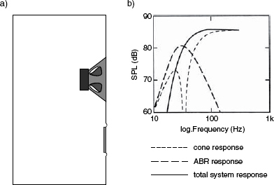
Figure 3.10 The ABR. a) A passive radiator (ABR) loudspeaker system. b) Cone and ABR contributions to the overall response
3.6 Bandpass cabinets
If the low frequency driver is enclosed with air volumes on each side of the cone, and the only radiation to the outside air is via a port in one of the air volumes, the result is a bandpass loudspeaker, as shown in Figure 3.11. Bandpass cabinets are usually restricted to use as sub-woofers because the pass-band is very limited – rarely more than one octave of flat response. The roll-offs at either end of their spectrum of use tends to be 12 dB per octave, because there is no direct radiation to give rise to the phase differences that lead to the 24 dB per octave lower roll-off rate of reflex enclosures, unterminated transmission lines or ABR systems. In the design shown in Figure 3.11, the lower roll-off frequency is governed largely by the inner, sealed chamber, and the upper roll-off frequency is governed by the outer ported chamber.
However, there do exist some designs with both chambers vented, generally in an attempt to gain overall system efficiency in the pass band. Bandpass enclosures can normally be much physically smaller than other configurations for any given output capability, but the responses, not surprisingly, tend to be resonant and thus exhibit poor transient responses. Figure 3.12 shows the design of a bandpass enclosure in which both chambers are ported, one to the outside and the other to the outer chamber. This results in a 24 dB per octave roll-off at the lower frequency. A further development is shown in Figure 3.13. In this instance, both chambers are ported to the outside, resulting in a 30 dB per octave roll-off at the lower frequencies and an 18 dB per octave roll-off at the higher frequencies. Both of the latter two designs were developed by the Bose Corporation.1
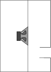
Figure 3.11 A typical bandpass enclosure
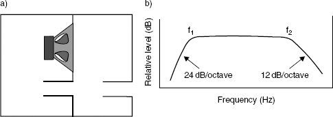
Figure 3.12 a) A bandpass enclosure with the inner chamber ported to the outer chamber. b) Roll-off responses of a)
Care must be taken in the acoustic treatment of the chambers which vent to the outside because internal resonances at high frequencies can escape through the ports if not dealt with internally. Care must also be taken when siting bandpass enclosures, because their proximity to solid boundaries may severely affect their response, and the high velocity ports must be free from obstructions. Some designers claim better response linearities due to reduced cone excursions for any given output SPL as compared to other low frequency loudspeaker systems, but their use with true high-fidelity systems is very limited due to transient response anomalies.
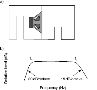
Figure 3.13 a) A band pass enclosure with both chambers ported to the outside. b) Roll-off response of a)
3.7 Series driver operation and isobaric loudspeakers
If the port in the outer chamber shown in Figure 3.11 were to be replaced by another drive unit, a system would result as shown in Figure 3.14, with the two drivers in acoustic series, (but with the drivers still connected in parallel, electrically). At low frequencies, the two drivers behave like a single driver with twice the moving mass. The result is a downward shift in resonant frequency to about 70% of that of just one of the drivers in the sealed enclosure. The reduced back-pressure exerted by the enclosure on the externally radiating driver will result in lower distortion because the inner loudspeaker is tending to keep the pressure in the outer chamber constant. However, in practice, the two drivers also tend to function as one due to the strong coupling by the trapped air mass. Teifenbrun first used the term isobaric for this type of operation – ‘isobaric’ meaning ‘same pressure’ (UK patent 1,500,711). Another variation on the theme is shown in Figure 3.15.
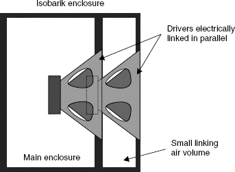
Figure 3.14 The Linn Isobarik enclosure concept. The loudspeaker drivers are connected in acoustic series (cascade), but electrically in parallel
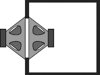
Figure 3.15 A variation on the theme of Figure 3.14
3.8 General discussion
Although there are many esoteric designs of low frequency loudspeaker systems on the market, the ones described so far in this chapter are the ones which will cover 99.9% of the loudspeakers to be found in the mainstream music recording and domestic reproduction environments. In general, high levels of fast, flat responses are not available from small enclosures. This subject is dealt with much more thoroughly in Chapter 11, but it seems obvious that nobody would choose to use large, expensive, unwieldy cabinets if more compact solutions were available. Nevertheless, despite the barrage of marketing claims about revolutionary low frequency sources, and a widespread tendency for many people to believe that computer control and signal processing can resolve any problems, the fact remains that the radiation of low frequencies is something that resides firmly in the domain of the laws of acoustics, and they tend to be somewhat inflexible. It should be noted that in nature, only large objects radiate low frequency sounds.
The tendency towards using compact, single, mono low-frequency sources is something that can greatly improve the overall response, both subjectively and objectively, in poor-to-quite-good circumstances of use. However, as the room acoustics become better controlled and the signal path, including the loudspeakers, becomes higher in resolution, the optimum choice for low frequency reproduction tends to return to favour stereo sources in integrated loudspeaker systems – i.e. without physically separated sub-woofers. What is optimum in the mid-to-reasonably-high quality range of loudspeaker systems may not necessarily be extrapolated as being best at the highest quality levels. One must be very careful not to generalise about things which are for specific applications. For example, an orchestral recording with phase differences in the left and right channels at low frequencies would benefit, in a good room, from stereo bass. It has now been determined that only by restricting the crossover frequency to less than 50 Hz can the bass be summed into mono without loosing the spaciousness in the sound5. However, in a poorly controlled room, a mono bass may lead to less general confusion if crossed over and combined into mono an octave higher. Such choices can be very circumstantially dependent.
3.9 Cabinet lining materials
Any hard-surfaced box will suffer from internal reflexions and resonances when excited by a loudspeaker drive unit mounted in one of its surfaces. The nature of cone loudspeakers is such that they are relatively transparent to sound at mid frequencies, so any reflexions and resonances occurring within the box are likely to pass to the outside via the cone, and combine with the directly radiating sound in a way that will give rise to undesirable colouration. One of the fundamental reasons for applying absorbent linings of foams or fibrous materials to the inside of loudspeaker cabinets is to reduce to inconsequentially low levels the colouration effects by rendering the boxes as acoustically non-reflective as is reasonably possible. A further advantage of the application of porous or fibrous materials is that they can slow down the speed of sound, and thus make the cabinets appear to be acoustically larger than they are physically. The practical limit to this size increase appears to be around 20% (which is still a useful gain) because the thermal transfer characteristics of the materials normally used are not sufficient to achieve the theoretical 41% maximum. As briefly mentioned in Section 3.2, air heats up when compressed and cools on rarefaction. Both of these effects tend to augment the speed of sound on the successive half-cycles because the air itself is a poor conductor of heat, so the thermal changes are trapped within the waves. However, if the air is in close contact with another material, distributed throughout its volume, which can conduct the heat, the augmentation of the speed of sound due to the heat of compression and the cold of rarefaction will not be apparent. The ratio of the speed of sound with and without this augmentation is about 1.41 to 1, hence the approximately 40% difference in apparent box size if the heat conduction were total.
Partly for this reason, but also because fibrous materials are better absorbers where the particle velocities of the air movement are at their highest (they must be zero at rigid boundaries, so they are at their lowest close to the boundaries), the absorbent materials are best placed in the volume of the box, lightly packed, and not only against the sides of the box. Reticulated (open cell) foams, glass fibre, mineral wool, bonded acetate fibres, polyester fibres and cotton-waste felt are all common lining materials. The cut-away view of the ‘transmission-line’ cabinet shown in Figure 3.9 illustrates the use of a synthetic foam lining which the manufactures specifically chose for its ability to maximally damp the line. Material types and densities are normally chosen with care for specific applications.
The KEF loudspeaker company, in the 1980s, noticed some differences in their loudspeaker frequency responses depending upon whether the excitation signal was of a steady state or transient nature. The discrepancy turned out to be due to non-uniform movement of some of the internal lining materials, which was somewhat uncontrolled after the shock excitation of a transient signal. The lining materials should therefore not be in panels which can vibrate en masse, or non-linear effects may be sufficient to be noticeable in the sound from the loudspeakers. Vibrating lining materials may settle into regular patterns on relatively steady signals, but can be excited rather unpredictably by transient shocks. At high SPLs, the linings can move in rather erratic manners, but the effects are usually swamped by the higher SPLs of the radiation direct from the driver. Nevertheless the ideal lining would be relatively inert. Colloms6 claims that unstable lining materials can impair the sense of ‘rhythm’ from a loudspeaker system.
At low frequencies, the thicknesses of the lining materials are far too little to provide much absorption, but the cabinets are normally also far too small to support any resonant modes (100 Hz would require an internal dimension of at least 1.6 metres) so the lack of absorption rarely becomes a practical problem. However, at higher frequencies, the absorption is important in order to reduce internal resonances which could powerfully excite structural resonances in the cabinet walls, and which would then radiate into the listening rooms.
3.10 Cabinet constructions
Above all, loudspeaker cabinets should be either rigid or heavy or both. A non-rigid (and/or lightweight) cabinet will be excited into vibration by the drive unit(s). In most cases, rigid materials tend to be heavy or expensive, so light, cheap loudspeakers always tend to be sonically suspect because they will probably suffer from cabinet vibration colouration. Any part of a cabinet which vibrates in sympathy with the driver diaphragm will, itself, act as a diaphragm and interfere with the driver output, leading to colouration of the overall sound output. In order to prevent the structural vibration of cabinets, sandwich constructions can be used, with lead sheet or plasticised deadsheets between the layers. Internal bracing is also an option, which pushes up the resonant frequencies into regions that tend to be more easily damped. Phenolic materials are another common choice because they can produce wood composites of very high density and rigidity. Lighter weight, highly rigid materials are sometimes to be found, in the nature of honeycombs or matrices, but they tend to be expensive and difficult to manufacture. However, in all cases, the goals are similar – rigidity and high vibration damping. It is important that the materials do not ring when struck.
The panel radiation is proportional to the size of the cabinet, so the problem of resonance avoidance becomes greater as cabinet size increases. For this reason, a given thickness of material for the wall of a small cabinet may need to be significantly increased as the cabinet size increases. The weight therefore increases greatly, because not only are the panel sizes larger, but they must also be thicker if the same vibrational insensitivity is to be maintained. Large loudspeaker systems of high quality tend to be very heavy indeed.
In many cases, a stiff, large panel, which is well-behaved at low frequencies may still ring at mid-frequencies, and a well-damped panel at mid frequencies may flex at low frequencies. Finding solutions which are dead at all frequencies is often difficult. In some of the more esoteric designs, mineral-loaded acrylics and Melamine are used as panel materials, but they can be very difficult to work with.
3.11 Cabinet shapes and diffraction effects
In many cases, modern loudspeakers, although basically of rectangular shape, have rounded or chamfered edges. Figure 3.16 reproduces the classic work of Olson7 on the subject of the diffraction effects on the overall loudspeaker response due to cabinet shape. The responses are for an identical drive unit in each cabinet. The sphere looks attractive, but difficulty of manufacture and problems due to all the internal axial reflexion path lengths being the same lead to practical problems in its implementation. Figures 3.16 J and L are reminiscent of many modern designs, and their validity is borne out by the response plots. Of course, with built-in/flush-mounted loudspeakers, the diffraction problem is nullified, which is one reason why so many professional monitors are so mounted.
At low frequencies, the sound from a loudspeaker cabinet is radiated spherically if the loudspeaker is mounted in free space. At higher frequencies, where the wavelengths are small with respect to the front face of the cabinet, the cabinet will tend to act like an infinite baffle, and the radiation will be hemispherical. At still higher frequencies, where the wavelengths are small compared to the radiating diaphragm, the sound will be beamed forwards, regardless of whether it is mounted on a baffle, or not. The diffraction effects largely arise at the transition between the first two zones of radiation, i.e. between the spherical and hemispherical radiation zones.
As a sound wave in this transition zone radiates away from a source on a finite-sized cabinet wall, it spreads out as it propagates in the manner of half of a spherical wave. When the wave reaches the edge of the wall, it suddenly has to expand more rapidly to fill the space where there is no wall (see Figure 3.17). There are two consequences of this sudden expansion. First, some of the sound effectively ‘turns’ the corner, around the edge, and carries on propagating into the region behind the plane of the source. Second, the sudden increase in expansion rate of the wave creates a lower sound pressure in front of the wall, near the edge, than would exist if the edge were not there. This drop in pressure then propagates away from the edge into the region in front of the plane of the source. The sound wave that propagates behind the plane of the source is in phase with the wave that is incident on the edge, but the one that propagates to the front is in phase opposition. These two ‘secondary’ sound waves are known as diffracted waves and they ‘appear’ to emanate from the edge; the total sound field may then be thought of as being the sum of the direct wave from the source (as if it were on an infinite baffle) and the diffracted waves. The edges of the cabinets can be thought of as small loudspeaker radiating in antiphase to the real driver. The direct wave exists only in front of the baffle; the region behind is know as the ‘shadow’ region where only the diffracted wave exists.
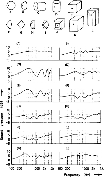
Figure 3.16 Olson's classic work on the effects of cabinet shapes on driver responses5
At low frequencies, the diffracted waves from all of the edges of the finite-sized cabinet sum to yield a sound field with almost exactly one half of the pressure radiated by the source of an infinite baffle. Thus behind the cabinet there is pressure due to the diffracted wave only, and in front of the cabinet there is the direct wave plus the negative-phased diffracted wave. Assuming that the edge is infinitely sharp (has no radius of curvature), there can be no difference between the strength of the diffracted wave at low frequencies and that at high frequencies (the edge remains sharp regardless of scale). The only difference, therefore, between the diffracted waves at low frequencies and those at higher frequencies is the effect that the path length differences between the source and different parts of the edge has on the radiated field. The diffracted waves from those parts of the edge further away from the source will be delayed relative to those from the nearer parts, giving rise to significant phase differences at high frequencies but not at low frequencies. The net result is a strong diffracted sound field at low frequencies and a weak diffracted sound field at high frequencies.
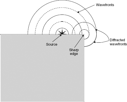
Figure 3.17 Graphical representation of the sudden increase in the rate of expansion of a wavefront at a sharp edge. The diffracted wave in the shadow region behind the source plane has the same effect as the wave incident on the edge; the diffracted wave in front of the source plane is phase reversed
Figure 3.18 shows the results of a computer simulation of the typical effect that a finite-sized cabinet has on the frequency response of a loudspeaker. Figure 3.18(a) is the on-axis frequency response of an idealised loudspeaker drive-unit mounted in a true infinite baffle. The response is seen to be uniform over a wide range of frequencies. Figure 3.18(b) is the frequency response of the same drive-unit mounted on the front of a cabinet of dimensions 400 mm high by 300 mm wide by 250 mm deep. The 6 dB decrease in response at low frequencies, due to the change in radiation from baffled to unbaffled, is evident from a comparison between Figures 3.18(a) and (b). Also evident is an unevenness in the response in the mid-range of frequencies. These response irregularities are due to path length differences from the diaphragm to the different parts of the diffracting edges and on to the on-axis observation point. Unlike the low-frequency behaviour, these are dependent upon the detailed geometry of the driver and cabinet and the position of the observation point. Therefore, in order to try to ameliorate these response irregularities, many loudspeakers have contoured edges. Although this does not eliminate diffraction, it tends to make the transitions from the baffled to the unbaffled conditions occur in a less abrupt manner, and thus have a less disturbing effect on the axial frequency response. The off-axis responses are also improved.
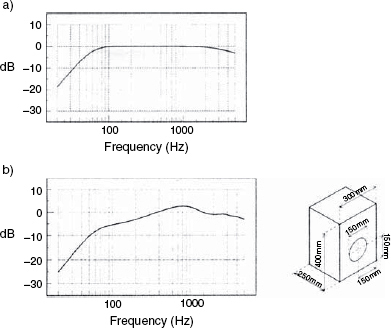
Figure 3.18 a) On-axis frequency response of an idealised loudspeaker diaphragm mounted in an infinite baffle: the response is uniform over a wide range of frequencies. b) On-axis frequency response of the same loudspeaker diaphragm mounted on the front face of a finite-sized cabinet (the rear enclosure size is assumed to be the same in both cases). The response has reduced by 6 dB at low frequencies and is uneven at higher frequencies. The differences between this and Figure a), above, are due to the diffraction from the edges of the cabinet
Although the combined effects of loudspeaker and rooms is the subject of Chapter 7, it is worth noting here the combined effect of cabinet diffraction and nearby surfaces. Figure 3.19 shows the effect on the axial response when the loudspeaker shown in Figure 3.18(b) is placed against, and close to, a wall. The different distances to the wall, behind the loudspeaker cabinet, give rise to different reflected paths for the diffracted waves, and hence different disturbance patterns in the on-axis, forward response. The clear advantage of flush-mounting the loudspeakers into a wall can be seen by comparison to Figure 3.18(a). Nevertheless, it should be notes that loudspeakers designed for free-standing may have had their low frequency responses engineered for a higher low frequency output, and flush-mounting them may result in an excess of low frequencies. Active loudspeakers often have filter controls which can compensate for this, and reflex cabinets can sometimes have their ports reduced in size such that a flat response can easily be restored. In other cases, a slight bass boost may be deemed to be more acceptable than the irregular response resulting from the diffraction. However, the bass rise due to the flush mounting is much more easily equalised than the diffraction irregularities, which tend not to be equalisable because of the complexity of the response delays from the reflexions.
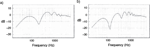
Figure 3.19 a) On-axis frequency response of the same diaphragm and cabinet as in Figure 3.18(b) but with the rear of the cabinet against a rigid wall. Interference between the direct sound from the loudspeakers and that reflected from the wall produces a comb-filtered response, but the response level at low frequencies is restored to that for the infinite baffle case (Figure 3.18(a)). b) As in a), above, but with the rear of the cabinet 0.25 metres from the rigid wall
In Figure 3.16, most of the drive unit positions are symmetrically placed. In practice, the diffraction effects can often be reduced by the non-symmetrical positions of the drivers with respect to the cabinet boundaries, but the necessity for this will depend upon the nature of the drive unit and the size of the cabinet. Some modern loudspeakers have the mid and high frequency drivers mounted in shallow horns, sometimes referred to as waveguides, which can project the wave in a more forward direction, and greatly reduce the effects of edge diffraction. In general, it is also important to keep the front surface of the loudspeaker system as smooth as possible by recessing the drivers and screw heads.
3.12 Front grilles
It is somewhat rare, these days, to see front grilles on loudspeakers for professional use. The fact is that there are no truly transparent grille materials, but in domestic use their use is strongly justified, not only for aesthetic reasons but also for protection against children and over-zealous cleaners. Fabric grilles usually require wooden frames, and these can become diffraction sources as they provide a step at the edge of the baffle. Foam grilles can avoid this problem, but self-supporting foams of sufficient thickness will exhibit different distances through which the sound must pass, dependent upon the angle of radiation. They can also obstruct the air flow in the ports of reflex enclosures (and open transmission lines) where the exits are on the front face of the cabinets.
However, in some cases, the grille losses have been taken into account in the design of the loudspeaker system, so the removal of grilles should not be undertaken without careful listening to the effects. The diffusive effects of some grilles have been reported to impair the stereo imaging of some loudspeaker designs. In general, the best grille is no grille from a purely sonic viewpoint.
3.13 Cabinet mounting
Figure 3.19 shows the effects of placing a loudspeaker near to reflective surfaces. Obviously, a floor standing loudspeaker should have been designed for standing on the floor, but the intended mounting conditions for small cabinets is not always so obvious. The well-known Yamaha NS10 was originally designed as a bookshelf loudspeaker for domestic use. Its response was therefore tailored such that its bass/mid/treble response was best balanced when the loudspeaker was placed with its back against a wall. This fact was partly responsible for its success when mounted on top of the meter bridges of mixing consoles, because the flat surface below the loudspeaker tended to reinforce the low frequencies in the same way as a wall behind the cabinet. Mounting this type of loudspeaker on a stand in free space will lead to a reduction in the low frequency response, but mounting the loudspeaker on a mixing console will cause time-smearing and comb filtering, the causes of which are highlighted in Figure 3.20.
Mounting loudspeakers on table tops or work surfaces is something that should be avoided, because the effects shown in Figure 3.20 will be exaggerated and colouration of the sound will be inevitable. Far too many people fail to realise that the mounting of a loudspeaker forms part of the loudspeaker system itself, and no loudspeaker's sound is independent of its mounting conditions. A poor loudspeaker, well mounted, may sound better than a good loudspeaker poorly mounted. The number of television and video studios in which the loudspeakers are really appallingly mounted indicates how little many of their users care about the sound, despite their protestations to the contrary.
Wall mounting of loudspeakers will need to take into account the nature of the wall, as not all walls can be considered to be rigid at low frequencies. The nature of the wall – plasterboard, hollow bricks, solid bricks, stone, concrete etc – will affect the loudspeaker response, so if the wall in the showroom was not the same as the wall at home, the same low frequency response will not be heard.
Placing loudspeakers on pieces of furniture is not recommended because of the vibrational coupling which will lead to sound being radiated by the furniture. Even so-called bookshelf loudspeakers should only be mounted on substantial bookshelves, which should ideally also be rather full of books, to add mass, damping, and reduce diffraction effects.
Heavy, narrow, floor stands are recommended, with wide bases for stability, and coupled to the floors (either wood, or carpeted) by spikes. Soft rubber pads are not usually a good idea because they can give rise to rocking; hard rubber is a better option. Broad, columnar stands can induce floor reflexion problems by obstructing the free passage of the sound below the cabinets. Under all circumstances, wobbly mounting systems should be avoided, because the imaging can be severely impaired, even by small movements of the cabinets.
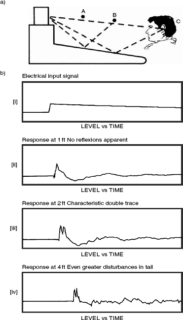
Figure 3.20 Effects of desk-top reflexions on transients. a) Positions A, B and C relate to the 1 foot (30 cm) 2 foot (60 cm) and 4 foot (120 cm)) responses, shown below. b) Transient responses at the positions shown in a), above
In effect, all of these different mounting regimes can be thought of as extensions to the loudspeaker cabinets, because they directly affect the loading on the diaphragms and the radiated sound output. They are not just simply different places to put a loudspeaker cabinet.
Note 1
In order to maintain a constant output SPL, a diaghragm needs to move four times the distance each time the frequency falls by an octave. The fact that the cone excursions are independent of frequency below the resonant frequency of a sealed box loudspeaker system is what gives rise to the 12dB/octave roll-off below that frequency.
References
1 Eargle, J. M., ‘Loudspeaker Handbook’, Chapman and Hall, New York, USA, (1997)
2 Small, R., ‘Direct Radiator Loudspeaker System Analysis and Synthesis – (Parts 1 and 2)’. Journal of the Audio Engineering Society, Vol 20, No 5, and Vol 21, No 1, (1972 and 1973)
3 Bailey, A. R., ‘A Non-Resonant Loudspeaker Enclosure Design’, Wireless World p 483–486, (October 1965)
4 Bradbury, L. J. S., ‘The Use of Fibrous Materials in Loudspeaker Enclosures’, Journal of the Audio Engineering Society, Vol 24, pp 404–412, (April 1976)
5 Martens, W., Braasch, J., Woszczyk, W., ‘Identification and Discrimination of Listener Envelopment Percepts Associated with Multiple Low-Frequency Signals in Multi-Channel Sound Reproduction’, AES 117th Convention, Pre-print No 6229, (October 2004)
6 Colloms, M., ‘High Performance Loudspeakers’, 6th Edition John Wiley & Sons, Chichester, UK (2005)
7 Olson, H. F., ‘Direct Radiator Loudspeaker Enclosures’, Journal of the Audio Engineering Society, Vol 17, No 1, pp 22–29, (January 1969)