
Chapter 4
Horns
No practical direct radiating loudspeaker can achieve high radiation efficiency at low frequencies. For example, a diaphragm with a diameter of 250 mm has a radiation efficiency of just 0.7% at 50 Hz when mounted in an infinite baffle, and half that when mounted in a cabinet. Sound power output is proportional to the product of the mean-squared diaphragm velocity and the radiation efficiency, so a low radiation efficiency means that a high diaphragm velocity is required to radiate a given sound power. The only way in which the radiation efficiency can be increased is to increase the size of the radiating area, but larger diaphragms have more mass (if rigidity is to be maintained) which means that greater input forces are required to generate the necessary diaphragm velocity. (This is discussed further in Chapter 11.) The electroacoustic efficiency is defined as the sound power output radiated by a loudspeaker per unit electrical power input. Because of the relatively high mass and small radiating area, electroacoustic efficiencies for typical loudspeaker drive-units in baffles or cabinets are of the order of only 1-5%. However, horn loudspeakers can combine the high radiation efficiency of a large radiating area with the low mass of a small diaphragm in a single unit. This is achieved by coupling a small diaphragm to a large area via a gradually tapering flare. This arrangement can result in electroacoustic efficiencies of 10-50%, or ten times the power output of the direct-radiating loudspeaker for the same electrical input. Additionally, horns can be employed to control the directivity of a loudspeaker and this, along with the high sound power output capability, is why they are used extensively in public address and sound reinforcement loudspeaker systems.
The following sections describe, in a conceptual rather than mathematical way, how horns increase the radiation efficiency of loudspeakers, how they control directivity, and why there is often the need to compromise one aspect of the performance of a horn to enhance another.
4.1 The horn as a transformer
Close to the diaphragm, in the hydrodynamic near-field, the change in area of an acoustic wave as it propagates gives rise to a ‘stretching pressure’ which is additional to the pressure required for sound propagation. In other words, imagine a balloon being inflated. As well as the outward movement of the skin, radially, the surface is also expanding laterally. Dots painted on the surface of the balloon would move apart as they moved away from the centre. The dots moving apart represent the stretching pressure which does not contribute to sound propagation as it is in phase quadrature (90 degrees) with the radial velocity, so the acoustic impedance in the near-field is dominated by reactance (for readers unfamiliar with the concepts of impedance, reactance and resistance see ‘Impedance’ in the glossary). As a consequence, large particle velocities are required to generate small sound pressures when the rate of change of area with distance of the acoustic wave is significant. It is this stretching phenomenon that is responsible for the low radiation efficiency of direct-radiating loudspeakers at low frequencies. Physically, one can imagine the air moving sideways out of the way, in response to the motion of the loudspeaker diaphragm, instead of moving backwards and forwards. In the hydrodynamic far-field, the stretching pressure is minimal, the acoustic impedance is dominated by resistance, and efficient sound propagation takes place. The only difference between the sound fields in the near- and far-fields is the rate of change of area with distance of the acoustic wave; the flare of a horn is a device for controlling this rate of change of area with distance, and hence the efficiency of sound propagation.
Horns are waveguides that have a cross-sectional area which increases, steadily or otherwise, from a small throat at one end to a large mouth at the other. An acoustic wave within a horn therefore has to expand as it propagates from throat to mouth. The manner in which acoustic waves propagate along a horn is so dependent upon the exact nature of this expansion that the acoustic performance of a horn can be radically changed by quite small changes in flare-shape. It is usually assumed in acoustics that changes in geometry that are small compared to the wavelength of the sound of interest do not have a large effect on the behaviour of the sound waves, so why should horns be any different? The answer lies in the stretching pressure argument above. The concept of a stretching pressure can be applied to horns by considering flare-rate. Flare-rate is defined as the rate of change of area with distance, divided by the area, and usually has the symbol m
![]()
Where S(x) is the cross sectional area at axial position x. The simplest flare shape is the conical horn, as shown in Figure 4.1, which has straight sides in cross-section, and where S(0) is the area of the throat (at x = 0) and x0 is the distance from the apex of the horn to the throat. The sound field within a conical horn can be thought of as part of a spherical wave field, and has a flare-rate which is dependent on distance from the apex.
The flare rate in a conical horn (and in a spherical expanding wave) is therefore highest close to the throat, decreasing with increasing distance from the throat.
The radial dependence of the flare-rate in a conical horn (and a spherical wave) gives rise to a gradual transition from the reactive, near-field dominated behaviour associated with the stretching pressure, to the resistive radiating, far-field dominated propagation as a wave propagates from throat to mouth. The transition from near- to far-field dominance is gradual with increasing frequency and/or distance from apex, so distinct ‘zones’ of propagation are not clearly evident.
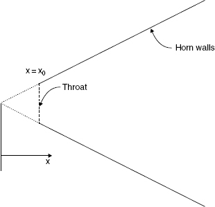
Figure 4.1 Geometry of a conical horn
The origin for the axial coordinates is usually considered to be the imagined apex of the cone
However, a more common flare shape for loudspeaker horns is the exponential. The flare shape of the exponential horn is shown in Figure. 4.2. The flare-rate of an exponential horn is constant along the length of the horn, giving rise to a behaviour that is quite different from the conical horn. At low frequencies, and throughout the entire length of the horn, the reactive, near-field-type propagation dominates, and, if the horn is sufficiently long, an almost totally reactive impedance exists everywhere. Above a given frequency, known as the cut-off frequency, throughout the entire length of the horn, the far-field-type propagation dominates, leading to an almost totally resistive impedance everywhere. The cut-off frequency of an exponential horn marks a sudden transition from inefficient sound propagation within the horn to efficient sound propagation. The cut-off frequency for any given horn is dependent upon its rate of flare. As the flare rate goes up (the horn expands more rapidly) the cut-off frequency also goes up, therefore rapidly flaring horns cannot be used at low frequencies.
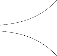
Figure 4.2 The flare shape of an exponential horn
Physically, propagation within an exponential horn above cut-off is similar to a spherical wave of large radius, with minimal stretching pressure. Below cut-off it is similar to a spherical wave of small radius, dominated by the stretching pressure. The sharp cut-off phenomenon clearly occurs because the transition from one type of propagation to the other occurs simultaneously throughout the entire length of the horn as the frequency is raised through cut-off. The acoustic impedance at the throat of an infinite-length exponential horn is shown in Figure 4.3, which clearly illustrates that, at frequencies below cut-off, the resistive part of the acoustic impedance is zero, which means that a source at the throat can generate no acoustic power. At frequencies above the cut-off frequency, the resistive part of the acoustic impedance is close to the characteristic impedance of air: a source at the throat therefore generates acoustic power with a radiation efficiency of 100% due to the perfect match.
In practice, horns have a finite length and so, unless the mouth of the horn is large compared to a wavelength, an acoustic wave propagating towards the mouth sees a sudden change in acoustic impedance from that within the horn to that outside, and some of the wave is reflected back down the horn. A standing-wave field is set up between the forward propagating wave and its reflexion, which leads to comb-filtering in the acoustic impedance. Figure 4.4 shows the radiation efficiency at the throat of a typical finite-length exponential horn. Also shown are the radiation efficiency of a conical horn having the same overall dimensions, and that of a piston the size of the throat mounted on an infinite baffle. The frequency scale is normalised to the cut-off frequency of the exponential horn. The comb-filtering, due to the standing wave field within the horn can be seen, as can the improvement in radiation efficiency of the conical horn over the baffled piston, and of the exponential horn over the conical horn at frequencies above cut-off.
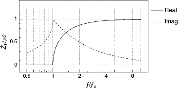
Figure 4.3 The acoustic impedance at the throat of an infinite length exponential horn f/fc is the ratio of frequency to cut-off frequency, and ρc is the characteristic impedance of air. No acoustic power can be radiated below the cut-off frequency as the real part of the acoustic impedance is zero
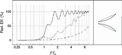
Figure 4.4 The radiation efficiency of an exponential horn compared to that of a conical horn (short-dashed line) of the same overall size. Relatively small changes in the flare shape of a horn can have a large effect on the efficiency at low frequencies. The third curve (long-dashed line) is the radiation efficiency of a baffled piston having the same size as the throats of the horns
The exponential horn acts as an efficient impedance matching transformer at frequencies above cut-off by giving the small throat approximately the radiation efficiency of the large mouth. The power output of a source mounted at the throat of a horn is proportional to the product of its volume velocity and the radiation efficiency at the throat; thus, a small loudspeaker diaphragm mounted at the throat of an exponential horn can radiate low frequencies with high efficiency. Below cut-off, however, the horn flare effectively does nothing, and the radiation efficiency is then similar to the diaphragm mounted on an infinite baffle. In practice, however, this seemingly ideal situation is marred somewhat by the sheer physical size of horn flare required for the efficient radiation of low frequencies.
The cut-off frequency is proportional to the flare rate of a horn, which in turn is a function of the throat and mouth sizes and the length of the horn. Therefore, for a given cut-off frequency and throat size, the length of the horn is determined by the size of the mouth. To avoid gross reflexions from the mouth, leading to a strong standing wave field within the horn, and consequently an uneven frequency response, the mouth has to be sufficiently large to act as an efficient radiator of the lowest frequency of interest. In practice, this will be the case if the circumference of the mouth is larger than a wavelength. For the efficient radiation of low frequencies, the mouth is then very large. Also, a low cut-off frequency requires a low flare-rate which, along with the large mouth, requires a long horn. By way of example, a horn required to radiate sound efficiently down to 50 Hz from a loudspeaker with a diaphragm diameter of 200 mm would need a mouth diameter of over 2 metres, and would need to be over 3 metres long! Compromises in the flare-rate raise the cut-off frequency, and compromises in the mouth size gives rise to an uneven frequency response. Reference 1 is a classic paper on the optimum matching of mouth size and flare-rate.
A radiation efficiency of 100% is not usually sufficient to yield the very high electroacoustic efficiencies of 10% to 50% quoted in the introduction of this section. However, unlike ‘real’ efficiency figures, which compare power output with power input, the radiation efficiency can be greater than 100% because the figure is relative to the radiation of acoustic power into the characteristic impedance of air ρ. Arranging for a source to see a radiation resistance greater than that of the characteristic impedance results in radiation efficiencies greater than 100%. A technique known as compression is used to increase the radiation efficiency of many horn drivers; all that is required is for the horn to have a throat that is smaller than the diaphragm of the driver, as shown in Figure 4.5
Assuming that the cavity between the diaphragm and the throat is small compared to a wavelength, it can be shown that the acoustic impedance at the diaphragm is approximately that at the throat multiplied by the ratio of the diaphragm area to the throat area, known as the compression ratio.
A compression ratio of 4:1 thus gives a radiation efficiency of 400% at the diaphragm. The ‘trick’ to achieving optimum electroacoustic efficiency is to match the acoustic impedance to the mechanical impedance (mass, damping, compliance, etc.) of the driver. If the compression ratio is too high, the velocity of the diaphragm will be reduced by the additional acoustic load and the gain in efficiency is reduced. This can, however, have the benefit of ‘smoothing’ the frequency response irregularities brought about by insufficient mouth size. Some dedicated compression drivers operate with compression ratios of 10:1 or more.
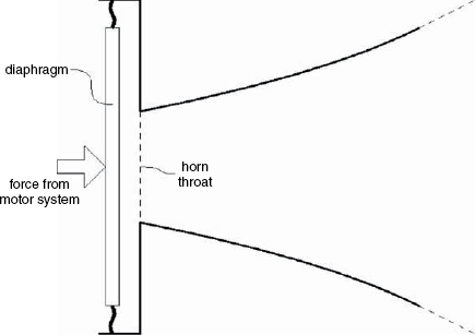
Figure 4.5 Representation of the principle behind the compression driver. Radiation efficiencies of greater than 100% can be achieved by making the horn throat smaller than the diaphragm
4.2 Directivity control
In addition to their usefulness as acoustic transformers, horns can be used to control the directivity of a loudspeaker. The directivity of a piston in a baffle narrows as frequency is raised, as was shown in Figure 1.4. For many loudspeaker applications, this frequency-dependent directivity is undesirable. In a public address system, for example, the sound radiated from a loudspeaker may be required to ‘cover’ a region of an audience without too much sound being radiated in other directions where it may increase reverberation. What is required in these circumstances is a loudspeaker with a directivity pattern that can be specified and that is independent of frequency. By attaching a specifically designed horn flare to a loudspeaker driver, this goal can be achieved over a wide range of frequencies.
Consider the simple, straight-sided horn shown in Figure 4.1. The directivity of this horn can be divided into three frequency regions as shown in Figure 4.6. At low frequencies, the coverage angle reduces with increasing frequency in a manner determined by the size of the horn mouth, similar to a piston with the dimensions of the mouth. Above a certain frequency, the coverage angle is essentially constant with frequency and is equal to the angle of the horn walls. At high frequencies, the coverage angle again decreases with increasing frequency in a manner determined by the size of the throat, similar to a piston with dimensions of the throat. Thus the frequency range over which the coverage angle is constant is determined by the sizes of the mouth and of the throat of the horn. The coverage angle within this frequency range is determined by the angle of the horn walls. This behaviour is best understood by considering what happens as frequency is reduced. At very high frequencies, the throat beams with a coverage angle which is narrower than the horn walls, as if the horn were not there. As frequency is lowered, the coverage angle (of the throat) widens to that of the horn walls and can go no wider. As frequency is further lowered, the coverage angle remains essentially the same as the horn walls until the mouth (as a source) begins to become ‘compact’ compared to a wavelength and the coverage angle is further increased, eventually becoming omni-directional at very low frequencies. The coverage angle shown in Figure 4.6 is, of course, a simplification of the actual coverage angle of a horn. In practice, the mouth does not behave as a piston and there is almost always some narrowing of the directivity at the transition frequency between mouth control and horn wall control. A typical example of this is shown as a dashed line in Figure 4.6. Different coverage angles in the vertical and horizontal planes can be achieved by setting the horn walls to different angles in the two planes.
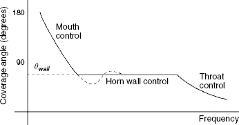
Figure 4.6 Simplified representation of the coverage angle of a straight-sided horn. At low frequencies, the coverage angle is determined by the size of the mouth, and at high frequencies by the size of the throat. The coverage angle in the frequency range between the two is fairly even with frequency, and is roughly equal to the angle between the horn walls ( wall). The dashed line shows a narrowing of the coverage angle at the lower end of the wall-control frequency range, which is often encountered in real horn designs
4.3 Horn design compromises
Sections 4.1 and 4.2 describe two different attributes of horn loudspeakers. Ideally, a horn would be designed to take advantage of both attributes, resulting in a high-efficiency loudspeaker with a smooth frequency response and constant directivity over a wide frequency range. However, very often a horn designed to optimise one aspect of performance must compromise other aspects. For example, the straight-sided horn in Figure 4.1 may exhibit good directivity control but, being a conical-type horn, will not have the radiation efficiency of an exponential horn of the same size. The curved walls of an exponential horn, on the other hand, do not control directivity as well as straight-sides horns. Early attempts at achieving high efficiency and directivity control in one plane led to the design of the so-called sectoral horn or radial horn shown in Figure 4.7. In this design, the two side walls of the horn are straight, and set to the desired horizontal coverage angle. The vertical dimensions of the horn are then adjusted to yield an overall exponential flare. Whereas the goals of high efficiency and good horizontal directivity control can be achieved with a sectoral horn, the severely compromised vertical directivity can be a problem. Given that a minimum mouth dimension is required for directivity control down to a low frequency, setting the horizontal and vertical walls to different angles, for example 90 degrees by 60 degrees, means that different horn lengths are required in the two planes. To overcome this problem, later designs used compound flares2 so that the exit angles of the horn walls can be different in the two planes, but the mouth dimensions and overall horn length remain the same. The so-called constant directivity horn (CD) is shown in Figure 4.8. The sudden flare discontinuities introduced into the horn with these designs result in strong standing wave fields within the flare which can compromise frequency response smoothness. In fact, this is true of almost any flare discontinuity in almost any horn. Modern public address horn designs employ smooth transitions between the different flare sections and exponential throat sections to achieve a good overall compromise, but constant directivity horns, because of the reflexion problems, tend not to be used on the highest fidelity loudspeaker systems.
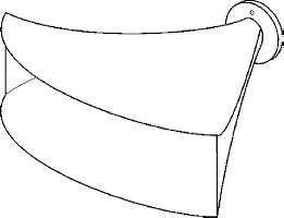
Figure 4.7 The sectoral (or radial) horn
The walls controlling the horizontal directivity are set to the desired coverage angle. The shape of the other two walls is adjusted to maintain an overall exponential flare, resulting in less-than-ideal vertical directivity
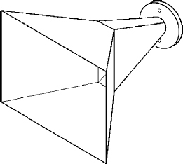
Figure 4.8 The constant directivity horn
Different horn wall angles in the two planes can be achieved using compound flares. Sharp discontinuities within the flare can set up strong standing-wave fields, leading to an uneven frequency response
The control of directivity down to low frequencies requires a very large horn. For example, in a horn designed to communicate speech, directivity control may be desirable down to 250 Hz at a coverage angle of 60 degrees. This can only be achieved with a horn mouth greater than 1.5m across. The same horn may have an upper frequency limit of 8 kHz, which needs a throat no greater than 35 mm across. Maintaining 60 degrees walls between throat and mouth then requires a horn length of about 1.3 m. Attempts to control directivity with smaller devices will almost always fail.
4.4 Non-linear acoustics
In the vast majority of studies in acoustics, and loudspeakers in particular, the acoustic pressures and particle velocities encountered are sufficiently small that the processes of sound radiation and propagation can be assumed to be linear. If a system or process is linear, then there are several rules that govern what happens to signals when they pass through the system or process. These rules include the principal of superposition, which states that the response to signal (A + B) is equal to the response to signal (A) + the response to signal (B). Most of the analysis tools and methods, such as Fourier analysis and the frequency response function, rely entirely on the principal of superposition, and hence linearity. When a system or process is non-linear, the principal of superposition no longer applies, and the usual analysis methods cannot be used. In this section, the conditions under which acoustic radiation and propagation may become non-linear are discussed, along with some examples of the degree of non-linear acoustic behaviour encountered in loudspeakers.
The speed of sound in air is dependent upon the thermodynamic properties of the air.
An acoustic wave consists of alternate positive and negative pressures above and below the static pressure and, as this is an isentropic process, the relationship between the instantaneous pressure and the density is progressively more non-linear as SPLs rise.
In linear acoustic theory, the relationship between pressure and density is assumed to be linear, which is a good approximation if the changes in pressure are small compared to the static pressure. A linear relationship between pressure and density means that the temperature does not change, so neither does the speed of sound. However, when the changes in pressure are significant compared to the static pressure, changes in instantaneous temperature, and hence the speed of sound, cannot be ignored.
In addition, when an acoustic wave exists in flowing air, the speed of propagation is increased in the direction of the flow, and decreased in the direction against the flow; the acoustic wave is ‘convected’ along with the flow. Although steady air flow is not usually encountered where loudspeakers are operated, the particle velocity associated with acoustic wave propagation can be thought of as an alternating, unsteady flow. Again, if the particle velocities are small compared to the speed of sound, the effect can be neglected, but in situations where the particle velocities are significant compared to the speed of sound, the dependence of the speed of propagation on the particle velocity must be taken into account.
The result of all of this is that the speed of propagation increases within increasing pressure and particle velocity, and decreases with decreases in pressure and particle velocity. For a plane progressive wave, positive pressures are accompanied by positive particle velocities, and the speed of propagation is therefore higher in the positive half-cycle of an acoustic wave than it is in the negative half-cycle. The positive half-cycle then propagates faster than the negative half cycle and the waveform distorts as it propagates. Figure 4.9 shows the distortion, known as waveform steepening, that occurs in the propagation of sound when the acoustic pressures are significant compared to the static pressure and/or the acoustic particle velocities are significant compared to the static speed of sound.
4.5 Examples of non-linear acoustics in loudspeakers
At the sound levels typically encountered when loudspeakers are operated, the effect of pressure and particle velocity on the instantaneous speed of sound is so small as to be negligible, and the resultant linear approximation is sufficiently accurate. However, there are some situations where this is not the case. Two common examples are the high sound pressures in the throats of horn loudspeakers, and the high diaphragm velocities of long-throw low-frequency drive-units.
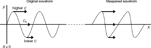
Figure 4.9 Waveform steepening due to acoustic pressures that are significant compared to the static pressure and/or acoustic particle velocities that are significant compared to the speed of sound, c0
The steepened waveform is no longer a sine wave, and therefore must contain harmonic distortion
When horn loudspeakers equipped with compression drivers are used to generate high output levels, the pressure in the throat of the horn can exceed 160 dB SPL, with even higher levels at the diaphragm. Sound propagation is non-linear at these levels and the acoustic waveform distorts as it propagates along the horn. If the horn flares rapidly away from the throat, then these levels are maintained only over a short distance and the distortion is minimised. Horns having throat sections that flare slowly suffer greater waveform distortion (it is interesting to note that the rich harmonic content of a trombone at fortissimo is due to this phenomenon). Nevertheless, investigations have shown that the distortion produced by high-quality horn loudspeakers only exceeds that from high-quality conventional loudspeakers when the horn system is producing output levels beyond the capability of most conventional loudspeakers.
The use of small, long-throw woofers in compact, high-power loudspeaker systems can also introduce non-linear distortion. The power output of a loudspeaker diaphragm is proportional to the square of the volume velocity of the diaphragm, so for a given sound power output the required diaphragm velocity is therefore proportional to the inverse of the diaphragm area. Consider two loudspeakers, one with a diaphragm diameter of 260 mm, the other with a diameter of 65 mm. In order to radiate the same amount of acoustic power at low frequencies, the smaller loudspeaker requires a velocity of 16 times that of the large loudspeaker, as it has 1/16 of the area. The rms velocity of the large loudspeaker when radiating a sound pressure level of 104 dB at 1 m at a frequency of 100 Hz is approximately 0.5 m/s. The same sound pressure level from the smaller loudspeaker requires 8 m/s. Whereas 0.5 m/s may be considered insignificant compared to the speed of sound (= 340 m/s), 8 m/s represents peak-to-peak changes in the speed of sound of around 8%.
A secondary effect, which is a direct consequence of particle velocities that are significant compared to the speed of sound, is the so-called Doppler distortion. If, at the same time as radiating the 100 Hz signal above, the small loudspeaker were also radiating a 1 kHz signal, the cyclic approach and recession of the diaphragm due to the low-frequency signal would frequency modulate the radiation of the higher-frequency signal by approximately 70 Hz. Hence long-throw woofers which are to be used at high SPLs need to cross over to mid-range drivers at relatively low-frequencies if Doppler distortions are to be avoided.
4.6 Practical horns in studios and homes
The previous sections have outlined in some depth the concept of the way in which horn loudspeakers work. This has been necessary before any meaningful discussions of horns can be undertaken because they are so poorly understood by the vast majority of people who use them. The normal state of affairs is that discussions about horns are based on hearsay, bad experiences due to the abundance of bad designs, and a widespread misapplication of good designs. In the worlds of public address and sound reinforcement, the directivity pattern control of horns is a very useful tool. The benefits of good pattern control normally greatly outweigh the more subtle aspects of their sound quality. Unfortunately, in the past decades, many horns which have been used in studio monitoring and domestic hi-fi systems have been based on sound reinforcement technology, and there has also existed a lack of understanding about how horn cross-sectional shapes can have detrimental repercussions on sonic purity.
The non-linear acoustics discussed in Section 4.4 can be a problem in horns. However, at the SPLs found in most music recording control rooms and homes, the non-linear propagation region is only occasionally reached on transient peaks at loud listening levels, and the audibility of such distortion on transient signals is unlikely to be very great. In fact, when other types of drive units are pushed to the same levels, they too may well be suffering from their own forms of non-linearities. Misunderstanding and poor designs have, over the years, created a lot of bad publicity for horns, yet some horns, such as the famous Tannoy 15 inch Reds and Golds have been the very antithesis of all that has been said against horns. As previously mentioned in Chapter 2, above about 1 kHz, these loudspeakers are nothing more and nothing less than compression drivers and axisymmetric horns. It has been quite remarkable how so many people have been heard to say that they cannot work with horns and yet have quoted the Tannoys amongst their favourite loudspeakers. Figure 4.10 shows a studio monitoring horn of the highest quality. It bears a remarkable similarity to the high frequency section of the Tannoy Dual Concentric shown in Figure 5.10. The development work which led to the horn in Figure 4.10 took four years to complete. The following summary is taken from Reference 3, which was based on the aforementioned research.
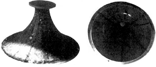
Figure 4.10 Axisymmetric horn geometry
The AX2 (see also Figures 8.6(a) and 8.16)
4.7 Implications for practical horn design parameters
By the very careful choice of design parameters and construction, horns can be produced for use above 1 kHz, or thereabouts, which approach the performance of electrostatic loudspeakers with their very low levels of deviation from their intended amplitude and phase (and hence time) responses. It would appear, however, that there are finite practical limits to the performance ranges over which horns can produce near optimum results:
1) The cut-off frequency of a horn is a function of its rate of flare. A low cut-off frequency demands a slow rate of flare.
2) If ‘horn-like’ sound characteristics are to be avoided in a practical horn, the length should not exceed 12 inches (300 mm) or thereabouts.
3) Taking 1 and 2 together, if a horn has a low flare rate, and cannot exceed 12 inches in length, then given a 1 inch throat diameter, and, say a 250 Hz cut-off frequency, the horn will inevitably have a small mouth area. There will consequently be an abrupt change in cross-sectional area when it meets the outside air. Samples 4 and 11 in Figure 4.11 highlight this point, [both were short, low flare-rate horns with small mouths] showing poor throat impedance linearity, or smoothness, especially near cut-off. Subjectively, although almost always being grouped with the direct radiators in the listening tests, as musical reproduction devices they were not considered smooth, flat, or natural, despite not sounding typically horn-like.
4) In order to achieve a smooth and trouble-free mouth termination, from a 1 inch throat of a horn not exceeding 12 inches (300 mm) in length (diaphragm to mouth), a mouth diameter of around 12 inches would seem to be the smallest practical size. This dictates a flare rate which results in a cut-off frequency in the order of 1 kHz, but can yield exceptionally smooth performance through cut-off if carefully designed; even allowing use through cut-off, and utilising the acoustic roll-off as part of the electroacoustic crossover (see Figure 4.12). [Sample 8 in Figure 4.11 shows the throat impedance plot of such a device.]
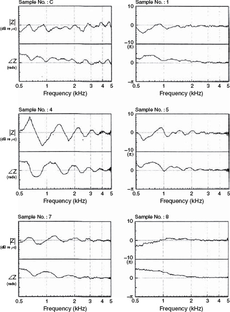
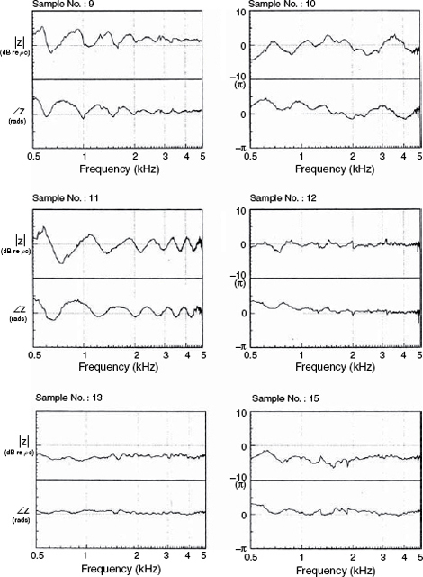
Figure 4.11 The logarithmic throat impedance plots of a selection of different mid-range horns. (This figure is continued on the next page)
5) To minimise internal disturbances which can cause disruption to both the on- and off-axis responses, all corners, angles and obstructions should be removed, rendering axial symmetry and smoothly contouring surfaces. Figure 4.11 shows the logarithmic throat impedance plots of all but one of the horns used in the tests. The vastly superior characteristics of the AX2 (Sample 8) can be readily seen.
6) ‘Squashing’ the axisymmetric shape into an ellipse would perhaps allow some change in directivity pattern without undue disturbance of the time response.
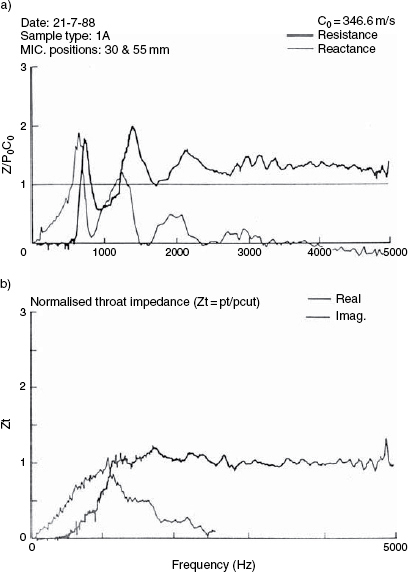
Figure 4.12 a) Throat impedance of a horn which has been widely used in studio monitor systems. The systems were generally considered to be typical of horn-loaded systems b) Throat impedance of the AX2 horn, showing an absence of reflexion-induced irregularities and a smooth impedance through cut-off. Systems using this horn have generally not been considered to sound horn-like
Sample 8, mated with the TAD 2001 drive unit produced what would seem to be a near optimum response in terms of both phase and amplitude (and hence time), smooth directivity, a very smooth overall performance from 1 kHz to beyond 20 kHz, and was deemed to be very musical, natural, transparent, and definitely not horn-like. It is interesting that in physical dimensions, though not in its drive system, it strongly resembles the Tannoy Dual Concentrics from around 40 years before. The fact that the shape and size were so similar to the Tannoy 15 inch Dual Concentric HF horn served to explain why the latter had enjoyed 40 years of use without being considered to sound horn-like. It would appear that the Tannoy, all those years ago, defined the physical limits for accurate performance, beyond which horns will begin to run into trouble.
Whether the engineers at Tannoy knew all of this at the time when the Dual Concentrics were first designed, or whether some of them merely ‘saw the logic’ of using a duly contoured bass cone for the horn of a co-axial system, and recognised that it sounded good, maybe we shall never truly know. In general, however, there is now no doubt that carefully designed horns and drivers can produce both sonic and measured performances as good if not better than the finest dynamic direct radiators, without any hint of a ‘horn-like’ sound. Indeed, to run a truly seamless 1 kHz to 20 kHz response within tight limits, whilst producing a very smoothly controlled directivity pattern (courtesy of a horn emanating a section of a spherical expanding wave, unlike a piston), a well designed horn and driver combination can be superior to the vast majority of direct radiators. If very high sound pressure levels are added to the list of requirements, there are few alternatives to horns.
4.8 Summary of results
The tests leading to the above conclusions are fully documented, eminently repeatable, and open to inspection. The initial findings suggest that short horns can be produced having high efficiency, wide frequency range and benign distortion levels, which are not sonically horn-like, and can be grouped as audibly similar to typical direct radiators. Much of the audible similarity of loudspeakers would appear to be in their time histories, and where a mouth reflexion effect of a horn is in the same order as any inherent reflexions in direct radiator units, then general audible grouping can be expected. Long horns produce longer reflexion delays, and sonically tend to group together, whilst electrostatics group together due to their rapid and accurate transient responses. In fact, much of the general audible similarity of all loudspeaker drive units of similar frequency range and general overall quality, irrespective of generic type, lies not in the nonlinearities, nor solely in the pressure amplitude response, but in the time domain response as specified by the linear distortions of the convolution of the amplitude and phase responses.
The AX2 was developed for the listening tests which led to the above conclusions at the Institute of Sound and Vibration Research (Southampton, UK) in 19894, 5. It was designed to have the minimum number of characteristics which previous research had suggested would lead to a horn-like ‘honky’ sound. The AX1 – Sample 4 in Figure 4.11 – was designed to maximise the horn-like characteristics. Neither the AX1 nor the AX2 were modelled on other loudspeakers, but were designed from first principles. As it turned out, the AX1 was physically remarkably similar to a horn of widespread use and of well-known manufacture which was often criticised for its harsh, nasal characteristics, and the AX2 resembled, physically, the sweeter sounding Tannoys. As mentioned in the earlier sections of this chapter, when mouths are designed from the requirement of associated components and directivity control only, the acoustic termination to the outside air is often very poor. This gives rise to strong reflexions from the mouths, which in turn give rise to the roller-coaster impedance plots typical of so many of the horns in Figure 4.11.
Conversely, the AX2 was designed to minimise the impedance irregularities, which was clearly successful (Sample 8 in Figure 4.11) but the size and directivity were the natural result of the design, and could not be controlled. Larger mouths could be smooth down to lower frequencies, but could give rise to difficulties in closely locating the adjacent drivers at crossover points. The practice of mounting high frequency horns and/or drivers on the central axis of the larger horn may ruin the mouth termination of the latter. The AX2 just about defines the practical limit for a MF/HF horn if the highest audio quality is the sole aim.
The fact that such strong evidence exists which discourages the use of horns below 1 kHz for the highest quality audio systems helps to explain why so many horn-loaded systems have received bad reviews.
Figure 12.18 shows a low frequency horn in a discotheque. This horn is flat down to 20 Hz. The floor mounting provides an acoustic mirror, so the mouth is effectively 4m×2m and the length is about 2 m. The loudspeaker cabinets behind the 1 m2 throat are over a metre deep, and in the throat are four 18 inch drivers. The sheer size of this horn precludes its use in studios or homes, but its size cannot be reduced without compromising its performance. In the discotheque it will produce 140 dB SPL, but the power level also has nothing to do with its response. Even if it was only required to produce 80 dB it would still need to be the same size. When a large array of relatively small horn-loaded bass cabinets are seen at a rock concert, the mouth areas combine to form one, composite mouth, equal to the sum of the sizes of the individual mouths. It is no use buying just one of the cabinets for a small venue and expecting the same response. So, the large arrays are not just for more volume, but also serve to extend the low frequency response by augmenting the overall mouth size and making a better mouth termination to the outside air.
4.9 General horn characteristics
The resistive load which the air presents to a diaphragm when loaded by a horn gives rise to rapid transient responses. Subjectively, good horns sound ‘fast’. The high sensitivity which is characteristic of most horn designs leads to small voice coil currents in powerful static magnetic fields. This tends to lead to less Bl profile distortion, because the integrity of the static magnetic field against which the voice coil field must push is much less disturbed as compared to a high voice coil current distorting the field of a weaker magnet in a heavier diaphragm, low sensitivity design. Despite many common beliefs, horn-loaded loudspeakers are capable of very low distortion reproduction if only the appropriate rules are respected and they are not pushed beyond the limits where the air, itself, is non-linear. In too many cases horns have been used which are too small for the frequency range in which they have been operated, and flare shapes have been used for their directivity performance with little consideration for the need for low colouration through the use of smooth contours.
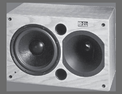
Figure 4.13 The Meyer HD2, using an axisymmetric horn and a non-compression driver
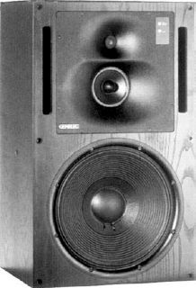
Figure 4.14 A Genelec 1038A loudspeaker system which employs vestigal horns, or ‘waveguides’, to load the mid-range and high-frequency drivers
Figure 4.13 shows a loudspeaker system which effectively horn loads a dome tweeter. In this case no compression driver is used. This is only one step away from the design shown in Figure 4.14, where vestigial horns are used as ‘waveguides’ (another name for horns) in a very popular studio monitoring loudspeaker. In fact, a direct radiator on an infinite baffle is mounted on a 180 degree horn of infinite flare rate. There is therefore no dividing line between direct radiation and horn loading. They are part of the same continuum which extends from the infinite 180 degree baffle to the infinite parallel pipe. It therefore follows that if somebody says that they do not like horns, one has to ask the question “Which horns?” The scope of what constitutes a horn is enormous, and so is the scope of the compromise points for any designs. Equally enormous, therefore, is the range of possibilities for making inappropriate compromises. Unfortunately, what we generally consider to be horns are relatively complex, precise devices, and hence are normally quite expensive when compared to direct radiators for use at relatively low SPLs. So, when corners are cut in the production process in attempts to reduce the costs, the sound quality usually suffers. Again, horns in general cannot be criticised because of the failings of badly engineered, cheap products.
The Tannoy Dual concentric concept has already been noted as not sounding horn-like, however the principle does suffer from two drawbacks. The high frequency horn is the cone of the bass driver, and it therefore moves, axially, with the low frequency signal. At high SPLs, the movement, peak to peak, can be a significant proportion of a wavelength at the highest audible frequencies, so some modulation effects are only to be expected, the degree of which are both level and frequency dependent. The Tannoys therefore tend to sound sweeter at low levels than at high levels. The second problem is that the voice coil gap, seen clearly in Figure 5.10, is a discontinuity in the throat of the horn, which on the larger devices can be a source of reflexions whose amplitude again depends upon the excursion of the bass cone. Nevertheless, despite these drawbacks, the concentric nature of the high and low frequency drivers facilitates the engineering of a relatively seamless crossover and a radiation pattern uniformity which many people consider to be sufficiently beneficial to offset the drawbacks of the designs, especially when listening levels are relatively low.
Another characteristic of the Tannoy design is that it uses a low-compression driver. As described in Section 4.1, high compression ratios are often used in order to increase the sensitivity of the driver by increasing the radiation resistance. However, if a high frequency horn loudspeaker is only to be used with a relatively inefficient low frequency driver, and at relatively low SPLs, there would seem to be no reason for compromising its sonic purity by using unnecessarily high compression. The choice of Tannoy has been to use low compression, low sensitivity, high frequency horn systems in most of their Dual Concentric designs.
4.10 Phasing plugs
A horn loudspeaker is shown in Figure 4.13 in which the diaphragm is mounted directly at the throat of the horn. No compression is used in this design as the diaphragm and throat are of the same diameter. By contrast, Figure 4.5 shows the concept of compression, where the diaphragm area is much greater than the throat area. Unfortunately, except for use as an electric klaxon or evacuation alarm, the design of Figure 4.5 would be of little use, because the pressure fluctuation from the perimeter of the diaphragm would take longer to reach the throat of the horn than the fluctuation from the centre of the diaphragm. The different distances from the different parts of the diaphragm to the throat of the horn would give rise to phase differences and severe losses at high frequencies. To overcome this problem, compression drivers use phasing plugs as shown in Figure 4.15.
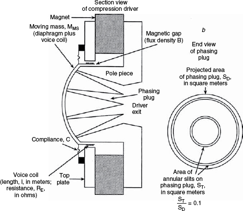
Figure 4.15 A typical phasing plug (courtesy of JBL Professional)
There are various types of phasing plugs, using either a series of tubes or axial slits to connect the various parts of the diaphragm to the horn throat via equal length pathways. The geometry of these needs to be very carefully controlled, because with a wavelength of only about 17 mm at 20 kHz, a path-length difference of only about 8 mm would reverse the polarity of the wave at the exit, and cancellation would result.
Because of the extreme sound pressure levels that can exist in the tubes, they represent one of the few situations in audio where actual air flow can result, leading us into the domain of aerodynamics rather than acoustics. Care must therefore be taken to avoid sources of turbulence, which can give rise to modulation dependent noises and gross distortion. The small size of the phasing plug tubes can also make visco-thermal losses significant.
4.11 Acoustics lenses
Figure 4.16 shows a selection of acoustic lenses, also known as a slant plates, chip-cutters, crinkle plates and pepper-pots. These were in vogue in the late 1960s and the 1970s and were developed as solutions to the problem of how to better match a short, slow-flaring horn to the outside air. They first came into use in the 1950s, in cinema loudspeaker systems, but took some time to find their way into the music recording studios. In all cases, the path through the centre of the lens is shorter than the path through the outer sections, and thus the wavefront was bent into a wider directivity pattern. Acoustic lenses worked well from a technical point of view, but could give rise to audible colouration. The time during which JBL used them for their studio monitor systems was quite short, but the high respect for JBL and the high profile of their users led to other companies copying them, and using them for many years after JBL had already abandoned them for studio quality monitoring.
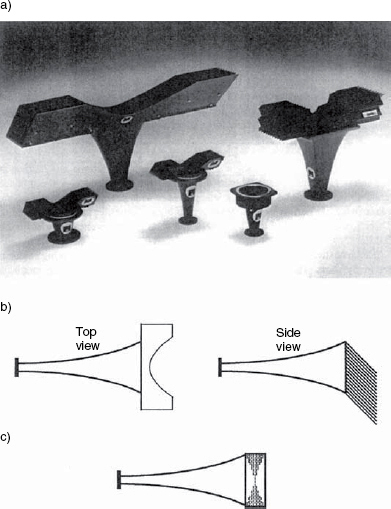
Figure 4.16 A family of acoustic lenses (courtesy of JBL Professional)
4.12 Horn types
Already mentioned in Section 4.3, and illustrated in Figure 4.7 was the radial horn, also known as the sectoral horn. The first name comes from the fact that the straight side walls in one direction form the radial lines of a circle, which meet at an imaginary apex behind the throat. They also have the appearance in plan view of a sector of a ‘pie-chart’, hence the name ‘sectoral’. For the highest quality subjective listening they have three basic problems. First, the cross-sectional shape must somehow be made to match the circular orifice of a compression driver. In some examples, even expensive ones, this was rather abrupt, leading to uncontrolled wave-expansion in the sensitive throat area of the horn. Such practices are simply begging for colouration due to reflexion problems. It has been shown that any discontinuity in the flare, especially near the throat, will give rise to reflexion-induced colouration3, 5. Figure 4.17 shows a cepstrum plot of an AX2 horn mated to an Emilar EK175 driver. The cepstrum plot is useful for identifying echoes or reflexions in signals or responses. [See Chapter 9.] The flare rate of the throat tube of the EK175 was not a precise match to the flare rate at the throat of the horn, even though both were perfectly circular, and the series of reflexion spikes before 2 ms was the result. When the AX2 was mated to the TAD TD2001 compression driver, the flare from throat tube to horn was continuous, and the reflexions disappeared.
The second problem with the radial horns is that the geometrical discontinuties at the junctions between the top, sides and bottom of the horns, even though not affecting the flare rate, can lead to off-axis colourations at normals to the discontinuities. In non-reflective environments this may not be a problem, but it can lead to coloured reflexions in more lively environments. The third problem involves the mouth termination, which is often achieved by means of rounded lips which project from the front baffle. These can lead not only to diffraction problems from the horn itself, but also from the obstructions which they may cause to the expanding wavefronts from the other drivers of the loudspeaker system. Dividers, which sectionalise some of these horns for improved directivity control also can act as diffraction sources. The general rule for horns for the highest fidelity is that nothing must disturb the flare rate, the flare should blend smoothly into the baffle, and no geometrical changes should exist other than the defined expansion rate. All of these things can detract from the sonic purity of the horn.
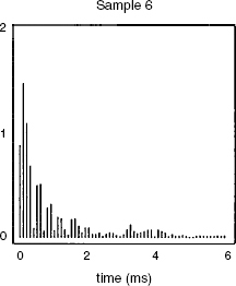
Figure 4.17 Power cepstrum of the Emilar EK175/AX2 combination. The series of diminishing echoes in the first 2 ms result from the flare-rate changes at the driver/horn junction
Diffraction horns are another type of horn. They have mouths that are wide in one direction and narrow in the other, the narrow dimensions relying on diffraction from a relatively sharp edge to widen the directivity. Unfortunately, diffraction necessarily introduces reflexions, and, as has just been stated in the last paragraph, for the highest fidelity, everything should be done to avoid reflexions in the flare of a horn. The constant directivity/uniform coverage horns also rely on the diffraction principle for the wide directivity of the higher frequencies, so the same comments apply. As discussed previously, attempts to take tight control of directivity come at a cost in terms of other aspects of horn response. In this case, the evenness of the throat impedance suffers from the reflexions given rise to by the diffraction. In general, when listening in rooms with highly controlled acoustics, the reflexion-induced colouration resulting from diffraction horns is noticeable. The exception to this is on very high frequency loudspeakers, say 7 kHz and above, where the reflexion delays are very rapid and the sensitivity to this type of colouration at such high frequencies is minimal.
Multicellular horns are rarely used nowadays, neither in studios nor cinemas. A multicellular horn, as shown in Figure 4.18, is a grouping of smaller horns which is designed to deliver an even frequency distribution over a desired area by means of the use of many narrow horns of uniform coverage angle. The mouth sizes sum, but unlike in the case of a radial horn of the same sized mouth, the high frequencies are less likely to loose contact with the walls because the individual horns are so narrow. Nevertheless, similar to the situation with the radial horns, the question arises as to how to match the throats of the compound horn to the throat of the circular driver without any discontinuities. However, some modern multicellular horns combine the horn cells with the phasing plug, thereby eliminating problems caused by the manifolds used in earlier designs. For a good compromise between sound quality and directivity control, a well-designed multicellular horn is hard to beat.
4.13 Materials of construction
There should not really be sonic differences between horn construction materials as long as they are sufficiently rigid and highly damped. However, if these conditions are not met, the horns can be excited into resonance, particularly noticeable on transient signals. Aluminium, solid wood, plywood, plastics and glass-fibre are all commonly used materials. The horn shown in Figure 8.2 is made from a specially selected Japanese apitong plywood, which is dense and highly damped. The horn shown in Figure 8.6(a) is made from glass-fibre which has been loaded with powdered slate. Some metallic horns have exhibited characteristic rings, but these have rarely found their way into studio monitoring or audiophile hi-fi loudspeakers. Nevertheless, in musical instrument amplifier use they have been used with no detrimental effect.
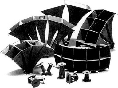
Figure 4.18 A family of multicellular horns showing the throat adaptors which, after changing section from round to square, must adapt the single driver to the multiple horn throats. This is very difficult to achieve in any precise manner (photo by Altec)
In many cases, the materials which have been used to make horns have been chosen for reasons such as ease of manufacturing or conditions of use. Massively heavy horns, for example, would be a poor choice for mobile sound reinforcement equipment where the benefits of their subtleties would be totally lost, so lighter weight materials have been the norm. Complex shapes have traditionally been easier to mould than to machine, so they have tended to be made from mouldable materials for manufacturing reasons, rather than for acoustic reasons. When material choices have been made for purely acoustic reasons, the results, such as the horns made from apitong plywood, have often been very expensive, and are actually only found in limited quantities. One result of this situation is that relatively few people have experienced what horns can achieve when the manufacture and marketing constraints are removed. Horns have suffered from a terrible history of compromise.
4.14 Vestigial horns and ‘waveguides’
Shown in Figure 8.6(c) is the sculpted baffle of a large Genelec monitor system. The fact that Genelec refer to them as Directivity Control Waveguides (DCWs) suggests that their prime design function is just that, but nevertheless they are horns. In the Genelec case, they only slightly increase the sensitivity of the drive unit. The principal difference between the AX2 in Figure 4.10 and the DCWs is that the compromise points are different. The AX2 aims at increasing sensitivity, and the waveguide role is secondary, whereas the priorities are reversed for the DCW. It is also true that the DCW does not use a compression horn, yet neither does the high frequency horn shown in Figure 4.13, which places the diaphragm of a tweeter somewhat similar to that which is used for the high frequencies in Figure 8.6(b) at the throat of a horn similar to the AX2. In the latter case, the extra sensitivity afforded by a compression driver was not necessary for a system so small as the Meyer HD2. The system in Figure 8.6(b) uses a titanium dome mid-range unit which is clearly mounted in a short horn for reasons of improved sensitivity and directivity control.
To many people, the mid-range loudspeakers shown in Figure 8.6 a) and d) are horn loaded, and the systems in Figure 8.6(b) and (c) are not horn loaded, yet the truth is that they are all horn loaded at the mid and high frequencies. In Morfey's ‘Dictionary of Acoustics’6 the definition of a horn is:
‘– a waveguide whose properties are arranged to vary monotonically from one end to the other, in order to produce a resistance in the lowest order waveguide mode.... that is many times larger at the driver end than at the opposite end’.
How many times larger is not specified. Therefore, by definition, a horn is a waveguide, and the continuum shown through Figures 8.6(c), 8.6(b), 4.13, 8.7 (the low compression Tannoy), 8.6(a) and 8.6(d) demonstrates a very wide range of increasing loading, but without any differences in the operating principles of the waveguide/horn effects. Even a conventional loudspeaker cabinet placed on the floor in the corner of a room is being loaded by a triangular cross-section low frequency horn, as shown in Figure 7.9.
Sculpted baffles are therefore nothing magic, but are based on sound acoustic principles. However, they were late arriving because until the advent of computer modelling and CNC (computer numerically controlled) machinery, their precise design and construction was difficult. Despite their complex shape, the desired overall flare rate must be maintained up to the point where they blend into the front panel.
4.15 Flare rates
Although the majority of horns are based upon exponential flares for the reasons given in Section 4.1, other flare rates are also used. Hyperbolic horns appear from time to time, but catenoidal and hypex horns have also been used. In fact the horn shown in Figure 4.10 begins its flare on the conical side of exponential, then passes through exponential. The design aim was to maintain the optimum phase response in the expanding wave leaving the mouth of the horn. The relationship between the three most common shapes can be seen from Figure 4.19.
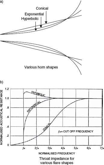
Figure 4.19 Comparison of flare geometrics. a) An infinite variety of shapes is possible between conical and hyperbolic. b) The drawing shows how the throat impedances for the three main types of horn varies with frequency
The throat cut-off frequency is determined by the rate of expansion of the horn. Doubling the horn length for a given mouth and throat size will halve the flare rate and lower the cut-off frequency by an octave. Halving the horn length will double the cut-off frequency, (raise it by an octave) if the throat and mouth sizes are kept constant.
As can be seen from Figure 4.19(b), exponential flares begin to loose their efficiency well above the normal cut-off frequency, which means that they are normally only used above about half an octave above cut-off. The hyperbolic horns function almost all the way to the theoretical cutoff, but the abrupt nature of their response fall-off can give rise to phase distortions which can lead to coloured responses. Nevertheless, for efficient public address applications this may not be a problem, and their amplitude benefits can be exploited.
At low frequencies, some loudspeaker cabinets use folded horns, but it is very difficult to maintain a constant flare rate around all the folds, so reflexions and resonances can be problems and response flatness can be difficult to achieve. Some rather complex shapes have historically been applied to such horns with varying degrees of success. Nowadays, however, with much more powerful low frequency drivers and amplifiers being available, the use of low frequency horns has become a rarity, except for sound reinforcement uses. Nonetheless, due to the resistive loading which the horn provides on the face of the driver, horn loaded bass systems are frequently liked for their characteristically fast and detailed subjective low frequency response.
Richard Small, in his 1970 paper ‘Constant-Voltage Crossover Network Design7’ highlighted this difference between horn-loaded and direct-radiating devices, and considered its implication for crossover design when used between horns and cones. He stated that whilst direct radiation diaphragm motion is largely mass-controlled, horn diaphragms are resistance controlled, and that the result is a constant phase difference of 90 degrees between the transfer characteristics of the two types of drivers. As previously stated in Section 4.1, the reactive loading (due to mass control) and the resistive loading (due to horn loading) are the mechanisms primarily responsible for the sensitivity differences – more power being radiated by the drivers which are resistively loaded, given the same electrical input.
References
1 Keele, D. B.Jnr., ‘Optimum Horn Mouth Sizes’, Presented at the 46th Convention of the Audio Engineering Society, Preprint No 933 (1973)
2 Keele, D. B.Jnr., ‘What Is So Sacred About Exponential Horns?’ Presented at the 51st Convention of the Audio Engineering Society, Preprint No 1038 (1975)
3 Newell, P., ‘Studio Monitoring Design’, Focal Press, Oxford, UK (1995)
4 Holland, K.R., Fahy, F. J, Newell, P. R., ‘Axi-symmetric Horns for Studio Monitoring Systems’, Proceedings of the Institute of Acoustics, Vol. 12, Part 8, pp 121–128, Reproduced Sound 6 Conference, Windermere, UK (1990)
5 Newell, P. R., Holland, K.R., ‘ Do All Mid-Range Horn Loudspeakers Have A Recognisable Characteristic Sound?’ Proceedings of the Institute of Acoustics, Vol. 12, Part 8, pp 249–258, Reproduced Sound 6 Conference, Windermere, UK (1990)
6 Morfey, C. L., ‘Dictionary of Acoustics’, Academic Press, London, UK and San Diego, USA (2001)
7 Small, R. H., ‘Constant-Voltage Crossover Network Design’, Journal of the Audio Engineering Society, Vol. 18 pp 172–180 (1970)