
Chapter 5
Crossovers
5.1 What is a crossover?
The term ‘crossover’ appears to have been originally used to describe the relationship of the filter slopes – crossover filters – as shown in Figure 5.1. In reality, and in many languages other than English, they are better described as frequency dividing networks, or words to that effect, though the name crossover has generally stuck. The fact that no loudspeaker drive unit suitable for music monitoring or serious listening can provide a flat response over the entire musical frequency range requires that the multiple drivers in a system need to be fed by signals which are only appropriate to their designed performance range. The two normal ways to apply these filtered signals are via high level, passive crossovers – where the filter components are placed between the power amplifier and the loudspeaker drive units, or low level active crossovers – where the filters are placed in the line level signal circuits, ahead of the amplifier inputs. In the latter case, each filter output feeds a separate amplifier, which is then directly connected to the corresponding drive unit(s). In some cases, mixtures of the two concepts are applied to one system, such as an active crossover between the bass and mid drivers, and a high level passive crossover between the mid and high frequency drivers, as shown in Figure 5.2.
Other forms of crossover also exist, such as simple, low-level passive crossovers, though they are rarely used because the filters can be more precisely tailored when the components are part of the feedback path in an electronic circuit. Mechanical crossovers are another type of filter. These can take the form of aluminium domes in the centre of the cones, which decouple from the main cone at higher frequencies and radiate separately, extending the frequency response above that which could be achieved by the main cone, alone. However, the response tends to be somewhat irregular, but this type of high frequency extension can find use in loudspeakers for music production – as opposed to reproduction – and the technique is extensively used in loudspeakers for musical instrument amplification, such as guitar amplifiers. An example is shown in Figure 5.3. Figure 5.4 shows a ‘parasitic cone’ or ‘whizzer cone’. The concept is generally the same in principle as that of the metal dome – the small cone decouples from the main cone at high frequencies – although the response of the parasitic cone tends to be more controlled, and a flatter frequency response can normally be achieved. Another concept, although not widely used, is inductive coupling, where the high frequency cone is not electrically connected to the amplifier. In fact, the coil can be the single, shorted turn formed by the metal dome itself. The dome and a former are simply placed over the centre pole of the magnet assembly, sharing the same gap as the LF/MF cone assembly. Such inductively coupled transducers, or ICTs, are operated by the modulated magnetic coupling between the ‘coil’ and the magnetic circuit. This type of ‘crossover’ is neither electrical, electronic nor mechanical, but is simply a magnetic-inductive effect.
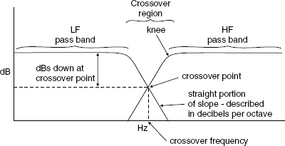
Figure 5.1 The basic concept of a pair of crossover filters
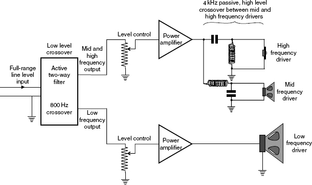
Figure 5.2 Example of a crossover system employing both active, low-level and passive, high-level filters
5.2 Reconstruction problems
Unfortunately, the division of the frequencies is not all that a crossover must achieve. They must divide the frequencies in a way that the individual drive units can re-construct in the acoustic far-field of the loudspeaker a representation of the waveform which was electrically applied to the electronic amplification system, and it is not an easy task to do so. Figure 5.5 shows a representation of a typical, two-way loudspeaker system. Note how, due to the physical requirement of the radiation of the different frequency bands, the sizes of the drive units give rise to a displacement of the voice coils if the front faces of the drives share a plane, common baffle. If the displacement were to be 10 cm, then a frequency with a wavelength of 20 cm would be received on the axis between the two drivers with its polarity reversed from either driver with respect to the other. The wavelength (λ) can be calculated by dividing the speed of sound (c), in metres per second, by the frequency (f) in Hz, so we arrive at the formula:
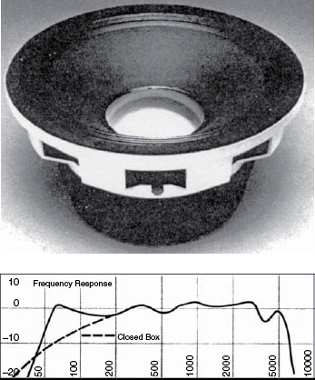
Figure 5.3 The Gauss model 4281, 12 inch (300 mm) drive unit for musical instrument use, which used an aluminium dome to extend the high-frequency response to over 5 kHz
![]()
To find the frequency with a wavelength of 20 cm, we can re-arrange the formula as:
![]()
Therefore:![]()
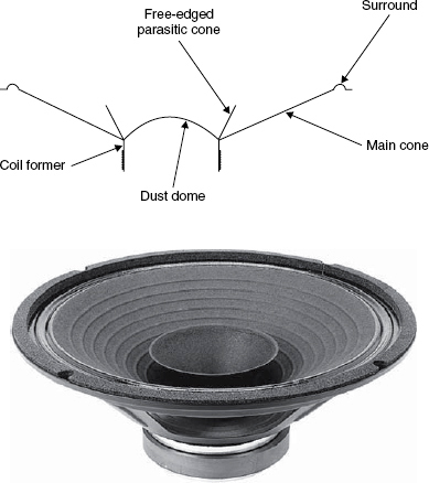
Figure 5.4 Parasitic, free-edged cone for high-frequency extension
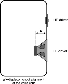
Figure 5.5 Elevation of a two-way loudspeaker system showing the typical offset of the voice coils in the axial plane
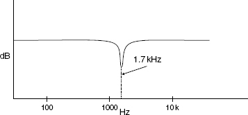
Figure 5.6 Composite response of the loudspeaker shown in Figure 5.5 on its central axis if the distance x were to be set at 10 cm
At 1700 Hz we would have cancellation on axis, producing a response as shown in Figure 5.6
However, this is not the only complication which arises in the reconstruction. All conventional filters exhibit the property of ‘group delay’. There is a finite time necessary for the information in a signal waveform to pass through a filter, which is a function of the slope of the filter and its cut-off frequency. As the frequency drops, the delay increases. As the steepness of the filter slope increases, so does the group delay. A filter of 24 dB/octave at 300 Hz would exhibit a group delay of around one millisecond. With a speed of sound of 340 m/s, one millisecond would represent 340/1000 m/s, or a 34 cm equivalent physical displacement. If the loudspeaker represented in Figure 5.5 were to be fed via such a crossover, the real radiation from the low frequency driver would be delayed by the equivalent of being mounted 44 cm behind the HF driver, (34 cm due to the filter and 10 cm due to the physical misalignment). Figure 5.7 shows the step-function responses of four loudspeaker systems with different degrees of arrival synchronisation from the drive units. Figure 5.7(d) shows the step response of a commercial 3-way loudspeaker which clearly exhibits delays between the arrival times of the individual drive units.
In effect, if not compensated for, the flat-response-axis of the loudspeaker shown in Figure 5.5 would be tilted, as shown in Figure 5.8, for moderate low frequency signal delays. Conversely, though, if we engineer a flat response on axis by compensating for the delays, it follows that the frequency responses off-axis must be incorrect, as shown in Figure 5.9. So, it can be appreciated that once the drive units have been physically separated, the problem of reconstructing the waveform of the original signal can become very difficult indeed. The problem can be partially solved by the use of concentric loudspeakers, but these concepts bring their own problems with them. For example, with the Tannoy, Dual Concentric approach, or the KEF Uni Q for that matter, the low frequency cone serves as a horn/waveguide for the high frequency driver. Modulating the LF cone with high levels of low frequencies can hardly be expected not to affect the high frequencies. In the case of the Tannoys, the LF coil gap also serves as an unwanted discontinuity in the HF horn. The general concepts of these drivers are shown in Figure 5.10, along with the Altec/UREI approach. In the latter case, the separate, concentrically mounted horn is left hanging in free air, but this method of mounting is really, too abrupt for proper mouth termination at the 1 kHz crossover frequency. The termination problem was discussed in detail in the previous chapter. Therefore, as so very often is the case with loudspeaker design, the tendency is to be trading one problem for another, rather than solving them – finding the best compromise for each situation – but that is often the reality of loudspeakers, which is something that will form the basis of discussion in Chapter 8.
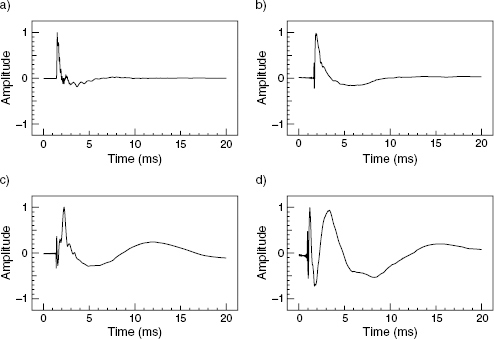
Figure 5.7 Step function responses with one, two and three drivers. a) Integrated attack of a relatively wideband, single driver. b) Integrated attack of two-way system with excellent time alignment. c) Separate rise times visible from the two drivers of a system with slightly delayed low frequency driver response. d) 3-way system with a clearly delayed response from the bass driver
In the latter case, the delay was a consequence of designing the system so that the main lobe of irregular response was forced upwards into a generally inoffensive direction. The trade-off was considered to be beneficial to the overall performance in typical situations in which is was expected to be used
5.3 Orders, slopes and shapes
Despite the different solutions on offer, electrical filters are overwhelmingly the most common manner of dividing the frequency bands. Whether this is done at high level, low level, actively or passively, the same basic filter concepts apply. Figure 5.11 shows a simple high pass filter, (a) to (d) showing first, second, third and fourth order roll-offs, respectively. Each inductor or capacitor adds 6 dB per octave of roll-off, and each 6 dB is known as an order of roll-off, a term which comes from the mathematical application of filter theory. An alternative approach to the inductor/capacitor (LC) design is a resistor/capacitor (RC) method shown in Figure 5.12. The LC approach is preferred for high level crossover in the loudspeaker/amplifier interface because the power losses are much less, but the RC approach is preferred in low level circuitry because of its simplicity (perfect inductors are not easy to make) and its relative insensitivity to drift and interference pick-up. In the active circuits, where gain is plentifully available, the higher losses of the RC circuits are of little consequence.
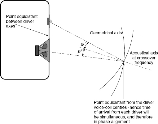
Figure 5.8 Tilting of the acoustic axis at the crossover frequency due to voice-coil physical displacement. On this axis, the response dip shown in Figure 5.6 would not be observed – the response would be flat
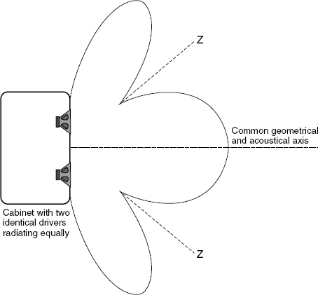
Figure 5.9 Lobing of the response when physically displaced drivers radiate a common frequency whose wavelength is close to, or smaller than, the distance between the drivers Z = axis of phase cancellation – varies with frequency – cancellation occurs whenever the distance to the two drive units varies by half a wavelength. The pattern shown therefore represents the situation at one frequency, only
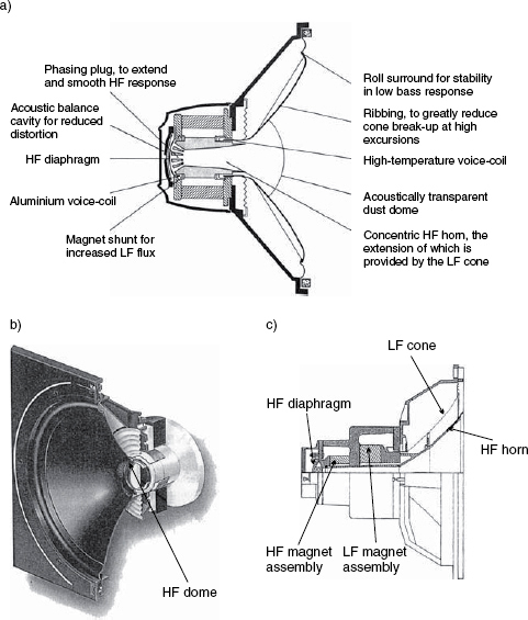
Figure 5.10 Some concentric drive units. a) Tannoy Dual Concentric – with Alnico magnet structure (courtesy of Tannoy Ltd) b) The KEF Uni-Q. c) The Altec 604
First order crossovers are rarely used, because the low rate of roll-off requires the individual drivers to have respectably flat responses for at least two, if not three, octaves each side of the crossover point, which is usually not practicable. Nonetheless, when they are able to be used, they have the advantage that they are the only conventional crossovers whose combined outputs reconstruct the input waveform. This is shown in Figure 5.13, and results from the fact that although each side of the filter is only 3 dB down at the crossover frequency (voltage summing would normally require that they should be 6 dB down to sum back to a flat response) the +45 degrees phase shift through one half of the crossover and the −45 degrees phase shift through the other half give rise to a 90 degrees combined shift which leads to another 3 dB of attenuation. The combination of amplitude roll-off and phase shifts leads to the perfect reconstruction shown in Figure 5.13.
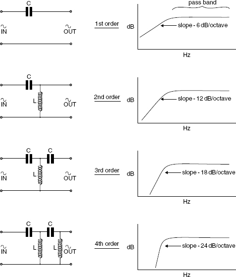
Figure 5.11 Capacitor/inductor filters – circuits and slopes. Values C and L depend upon the turnover frequency and the load impedance
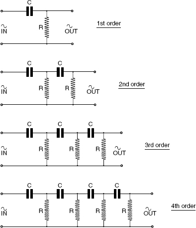
Figure 5.12 Resistor/capacitor equivalents of the filters shown in Figure 5.11
Except for the first-order filter, and where the R is supplied by the loudspeaker load impedance, these filters are not suitable for use as high-level filters because of the excessive power dissipated in the resistors. Values of C and R depend on the turnover frequency and the load impedance
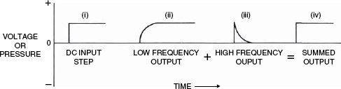
Figure 5.13 6 dB/octave crossover waveform reconstruction
Second order crossovers, with their 12 dB/octave roll-offs, are very popular with the manufacturers of small, two-way cabinet loudspeakers. They are relatively cheap to construct and the power losses through the filters are quite small, but, as can be seen from Figure 5.14, they will not reconstruct the original waveform. The group delays associated with the phase shifts cause a temporal offset between the two halves, so the reconstruction is not summing the two outputs at the same instant. This ‘latency’ in one half of the filter, relative to the other, creates a phase shift at the crossover frequency which does not compensate for the amplitude summation; hence the time and amplitude summations shown in Figure 5.14(a). Despite the fact that the reversing of the polarity of one of the outputs yields a flat amplitude response, the time response (waveform) becomes even more distorted. This is shown in Figure 5.14(b). There are ways of ‘juggling’ this arrangement by offsetting the 3 dB down points so that the filter sections overlap, but this can introduce other irregularities unless it is very carefully implemented. However, in general, a standard second order crossover yields either a flat frequency response or a synchronous time response, but cannot exhibit both properties at the same time.
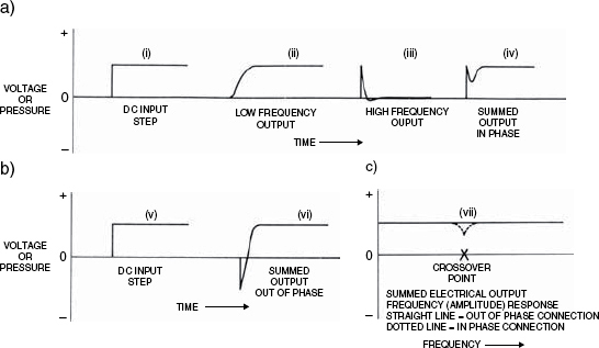
Figure 5.14 12 dB/octave crossover waveform reconstruction. a) In-phase. b) Reversed polarity. c) Amplitude responses
Note that whichever polarity is applied, the output waveform is not a true representation of the input waveform. (The waveform in Figure 5.13 reconstructed perfectly)
Third order crossovers, with slopes of 18 dB/octave are popular in more expensive passive loudspeaker systems, and are not infrequently used in active crossovers. They are more expensive in the passive form than the second order types, not only because they use more components, but also because the components may need to be less lossy. Otherwise, with so many components between the amplifier and the drive units, they would begin to sap considerable power from the signal. Typical circuit diagrams are shown in Figure 5.15, and a response summation is shown in Figure 5.16. The 18 dB/octave roll-off is useful in reducing the disturbance from out of band irregularity of the driver responses, because the driver responses can be almost 20 dB down an octave beyond the crossover frequency. This allows drivers to be used over almost all of their flat response region, but with third-order crossovers there is no ‘correct’ polarity relationship between the outputs. The phase responses for normal and reversed polarity are shown in Figure 5.17, and the reverse polarity connection actually exhibits less phase shift through the crossover region after the summation of the outputs. However, this is the effect of simply summing the electrical outputs. Once those outputs are connected to physically displaced loudspeakers the story can be rather different.
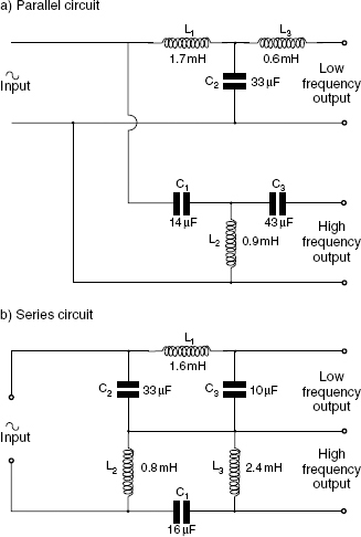
Figure 5.15 Typical, 2-way, 18 dB/octave, 3rd order passive crossover circuits
Approximate values shown for 1 kHz crossover frequency and a uniform loading of 8 ohms
Figure 5.16 Summed output of a 3-way, 18 dB/octave crossover
The signal path delays through the individual filter sections are clearly evident
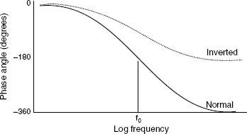
Figure 5.17 Phase relationships through the crossover region for the normal and inverted polarity connection of a third-order Butterworth crossover – f0 is the nominal crossover frequency
One of the most popular types of crossover filter for use in active designs is the fourth order Linkwitz-Riley. The 24 dB/octave slope is achieved by cascading a pair of Butterworth (see next section) 12 dB/octave crossovers. The 24 dB/octave slopes are beneficial in high-power loudspeaker systems, where out-of-band energy is rapidly cut off, and for use with drivers whose out-of-band response is also irregular. The power response exhibits a dip at the crossover frequency, but the width of the dip is so narrow as to be, in many cases, almost inconsequential. The on-axis amplitude response is flat, because each section is normally designed to be 6 dB down at the crossover frequency. The two outputs sum to unity (−6dB = half voltage [or half pressure], therefore 1/2 + 1/2 = 1) because each section of the crossover is rotated 180 degrees, and the overall response therefore remains in phase. However, due to the shape of the polar response, there are dips off axis at the crossover frequency, hence the dip in the total power response. The degree of audibility of this effect depends on how much reflected energy is returned to the listening position. In typical highly damped control rooms, the effect is usually imperceptible close to the axis and around the typical principal listening positions. With these crossovers, the narrowness of the band of frequencies over which the drivers on either side of the crossover frequency are simultaneously radiating ensures that the interference effects are kept small.
Filter orders higher than fourth are not normally used in crossover pairs, but they can sometimes be found in asymmetrical designs, such as a sixth order with a second order, to help to compensate for group delays or physical alignment delays. These individual filters sometimes also have their 3 dB or 6 dB- down points offset in frequency, in order to achieve a flat on-axis response or flat power response, depending upon the circumstances. In practice, filters above sixth order are rarely used because they tend to serve no useful purpose, and due to their tendency to introduce time response anomalies may actually create more problems than they can solve.
5.4 Filter shapes
Until now we have been looking at standard filters, where, for generating higher orders, the filters are simply repeating the characteristics of the first order sections. However, different entry slopes and different response shapes can be contoured by adjusting the components which are used to derive the higher orders. Therefore, by adjusting the Q of the filter, the ‘knee’ of the curve – between the flat response and the uniform slope – can be adjusted in shape to produce either a more abrupt or more gradual entry to the final roll-off. The modified shapes can be used to help to achieve the desired, overall electro-acoustic response when the individual responses of the drivers are taken into account, or when system summation is affected by physical displacement problems. Many different Q factors – or quality factors – are in use. Butterworth filters are ‘maximally flat’ until the roll-off begins. Bessel filters are more abrupt in their transition from flat to sloping response, but exhibit alternating up and down responses before the main roll-off begins. Figure 5.18(a) shows a typical 6 dB/octave roll-off produced by a simple capacitor-resistor filter, but Figure 5.18(b) shows how the addition of an extra resistor can limit the rate of roll-off. There are therefore means at our disposal to modify the slopes of the curves of the filters, which is extremely useful when we have to tailor curves to mirror the responses of real drivers, which never behave like pure resistors, and so can never ideally terminate the standard filters which were discussed in Section 5.3.
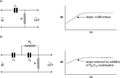
Figure 5.18 Response contouring. a) A simple high-pass filter of first order characteristic roll-off. The response will be 3 dB down at the frequency where the reactance of the crossover equals the resistance (R). Note, a resistor having the same value as R, substituted for C, would give rise to a 6 dB reduction of level at the output. The 90 degree phase shift through the capacitor is the reason for the 3 dB difference. b) Added components for reducing the slope
Figure 5.19 shows an example of a conjugate network. These are used to flatten the impedance curves of drive units by compensating for the reactive properties of their electro-mechanico-acoustic characteristics. However, the resistors in these networks do dissipate power, so the overall efficiency of the system may reduce when conjugate networks are applied. Sonically, they can be questionable, and some complicated passive crossovers applying such technology for electrical and response flattening purposes have been considered to sound worse than simpler networks, but the overall effect may also depend on whether the power amplifiers with which they are used are capable of driving complex loads, or not. If they are not, then the conjugate networks may be helpful, but in professional situations, the choice of a more load-tolerant amplifier is often the preferred solution. Complex passive crossovers are not entirely distortion free, because the inductors, in particular, can produce non-linear distortion. Cases tend to need to be judged individually, partly because, as will be discussed in the next chapter, amplifier outputs stages and power supplies vary so widely in design concept.
Clearly, where complex circuitry is involved, it is essential to use components whose values remain stable if the performance of the overall system is not to change as time passes. Unfortunately, the large electrolytic capacitors which tend to be required by high-power, low frequency passive crossovers are notoriously prone to changing their capacitance as they age. Likewise, changes in mechanical compliances of the drive units with age can also cause a drift in the circuit parameters. These factors tend to put high-level, passive crossovers at a disadvantage when compared to low level active circuitry, especially when precise tailoring of the response is required. The higher impedance, active circuitry of the latter case can avoid the use of large value capacitors, and can therefore employ smaller value components of much greater long-term stability. This is an important concern when we need to produce very precise response curves. Active circuitry can also eliminate the need for lossy, and potentially non-linear inductors.
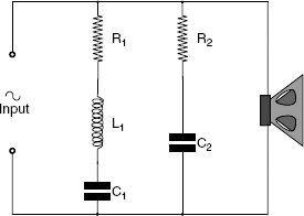
Figure 5.19 A conjugate network
Figure 1.5 shows the impedance curve of a typical low frequency driver. In the circuit above, R1, C1, and L1, provide compensation for the impedance rise at the resonant frequency of the driver, whilst R2 and C2 compensate for the rising impedance at higher frequencies due to the voice-coil inductance. Opinions vary about the sonic effects of this type of impedance equalisation, but such circuits are undoubtedly useful to flatten the response of systems using hi-order, passive crossovers
5.5 Target functions
Until as late as the 1970s it was commonplace to treat a moving coil loudspeaker as if it were a resistor when designing crossover circuitry, but, as we saw in Chapter 1, this is usually a long way from reality. In fairness, before the 1970s, and the seminal work of Thiele and Small1,2,3,4,5,6, it was not always very easy to find the necessary electro-mechanical information about drive unit characteristics, so design and development were often two separate processes – design it ideally, and then select components during tests, to modify the response. Since the 1980s, with much more data available, it has been customary to look at a drive unit as a complex impedance, and to view its response for what it actually is, and not as an ideal response. There has subsequently emerged the concept of the ‘target function’.
Whereas in Figure 5.1 the plots represent the responses of the filter circuits which presume that the driver is of constant impedance and has a flat acoustic response, we can also view the same plots as the target response for our combined electro-mechanico-acoustic system. In order to achieve this, the desired filter response becomes whatever is required to combine with the actual driver response to realise the target response. Figure 5.20(a) shows a target response; (b) shows the response of an actual driver, and (c) shows the response of a filter which, when used with (b) will yield the response shown in (a). This ‘new’ approach obviously calls into question the value of purchasing ready-made crossovers as stand-alone devices, be they active or passive. They may be of value for sound reinforcement systems, where each loudspeaker box has been engineered to be more or less flat, and multi-band system equalisation is de rigueur, but their use may be over-simplistic when applied to many other loudspeaker systems. Also, many modern drive units are not necessarily engineered for flat responses if other benefits can be gained by sacrificing the flatness. Computer-aided filter design can then be applied in order to design a crossover which will achieve the required target function from the complete system. In fact, in the current cost-conscious world, it is often less expensive to use electronic means to flatten a response rather than electro-mechanical means. Nonetheless, despite having said that, there is still in the experience of many listeners a certain je ne sais quoi about the purity of sound of an inherently flat driver. It should also be acknowledged that the more complex filter shapes such as that shown in Figure 5.20(c) are much more easily implemented with active crossover designs.
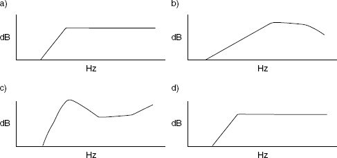
Figure 5.20 Target functions –practical realisation. a) Desired target function. b) Measured driver response. c) Electrical filter response – allows for a non-flat driver response. d) System response as measured – equal to a), i.e. it achieves its target
5.5.1 Minimum and non-minimum phase effects
The selection of the target function is somewhat more complicated than it may initially appear, because the phase shifts and group delays associated with the filters, and the physically induced delays due to the different drive units occupying different points in space, lead to non-minimum-phase responses. A minimum-phase response is one where the correction of the amplitude towards a flat response also leads to a corresponding flattening of the phase response, or vice versa. In the case of a non-minimum phase response, the correction of either the amplitude or the phase response does not automatically correct the other. Non-minimum-phase responses give rise to situations where a flat amplitude response cannot be accompanied by an accurate transient (time) response. The amplitude and phase responses are defined by the time response, and vice versa, which is why the Fourier Transform and Inverse Fourier Transform can be used to derive the frequency response from the impulse response or the impulse response from the frequency response. [For more on this subject, see Chapter 9.] The frequency response, in this case, is referring to the complete frequency response, i.e. the amplitude and the phase. Non-minimum-phase effects are typically associated with the recombination of non time-synchronous signals, such as a recombination of a reflexion with a direct signal, or the summation of signals where different group delays or digital latency have been incurred.
Unfortunately, for loudspeaker designers and users, the non-minimum-phase effects often prevent the perfect reconstruction of a waveform from a multi-drive unit loudspeaker system. When this fact is coupled with the fact that no single drive unit can cover the whole frequency range in a manner which is flat in frequency response and adequate in its directivity pattern (at least not at useful sound pressure levels) we are condemned to compromise. The time-shifted sections of the overall response cannot be equalised flat in a minimum-phase manner, and so the transient responses and directivity patterns will be altered. Even when using concentric drivers, where the vertical and lateral displacements can be avoided, the problem of the crossover group delays still dogs the design process, although, if crossover frequencies are carefully matched to distances on the front/back plane, they can sometimes almost be eliminated. The effects of trying to equalise non-minimum phase responses are clearly shown in Figures 11.17 and 11.18, in which the time response aberrations are very evident.
5.5.2 Corrective measures and side-effects
In some cases, the electrical crossover filters can be overlapped to some degree, in order to take into account certain physical aspects of the relative driver positions and in order to vary the polar pattern of the complete system. Lobes in certain directions may or may not be problematical dependent upon the intended position in which the loudspeaker is expected to be used, for example, see Figure 5.21. If a loudspeaker system does exhibit a lobed radiation pattern with an aberration in the frequency response, then that lobe is best directed towards places where there is least likelihood of returning a reflexion to the listening position which would be detrimental to the overall perception of the music. Decisions must also be made about whether the most likely movements of the listener to the loudspeaker will be in the horizontal or vertical direction when the loudspeakers are in critical use. For example, either sitting in a chair whilst moving left or right along a mixing console, or working predominantly in one place but at various times either sitting down or standing up.
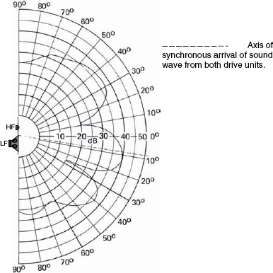
Figure 5.21 This type of lobing could be problematical if an irregular frequency response returns towards the listener from a reflective floor. Some designers choose to invert the cabinet in order to direct the irregular response above the listeners’ heads, especially if the ceiling is high, or more absorbent than the floor
In Section 5.3 it was described how a first-order crossover could reconstruct a perfect waveform. However, if the crossover is used with physically non-coincident drivers, then even a first order crossover will suffer from the above problems except on its acoustic axis, which may not always correspond with its physical axis. This means that off-axis reflexions would not have time-coincident origins, and there would be a lobe which was tilted, either upwards or downwards. One reason for the great popularity of the fourth order Linkwitz-Riley filters for high quality monitoring is that the in-phase relationship between the two drivers on either side of the crossover gives rise to the main lobe being symmetrical about the central axis between the drivers.
A very important point to emphasise here is that the design of crossover filters is not by any means the easy task which many people believe it to be. Many things must be taken into consideration before the filter functions can be decided upon, and the design of suitable filters can be work of a very specialised nature. Computer aided design of filters has been a great boon to loudspeaker engineers.
5.6 Active versus passive crossovers
For high quality loudspeaker applications, the consensus is almost universally in favour of active crossovers. By virtue of their feedback loops they can remain remarkably stable over very many years, and complex filter shapes can be devised without any loss of power efficiency. Conversely, passive crossovers rely entirely on the long term stability of each component part for their overall stability, which is not easy to achieve when the low impedances of loudspeaker circuits call for high value capacitors – both in terms of capacitance and working voltage – which in turn call for capacitors of types which may not be able to provide good, long-term stability. Complex filter shapes may need to use many components, which when placed in the power circuitry will probably lead to lower system efficiency, wasting many watts of amplifier output. If large electrolytic capacitors are needed, their stability can be questionable, but, if the much larger, solid dielectric capacitors are used, their physical construction and large size can lead to them having considerable unwanted inductance, which can upset the crossover operation.
Active filters are free from these problems, and in fact require no inductors at all. What is more, if state-variable filters are used, any drift which does occur can reflect equally in both halves of the crossover response, thus only slightly varying the crossover frequency as opposed to opening a gap or causing an overlap. The overall frequency response of the system is therefore unlikely to be affected. There can be no equivalent to this type of stability or self-correction with passive crossovers, and neither can passive crossovers easily compensate for group delays. Figure 5.22 shows a passive all-pass circuit (an analogue delay circuit) of a type which has been applied commercially to loudspeaker systems, but there are people who feel that this type of circuitry between an amplifier and a loudspeaker can again cause as many problems as it solves; if not more!
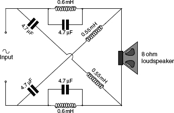
Figure 5.22 An all-pass delay circuit
Tannoy developed a delay circuit similar to the one shown, but unwanted phase-shifts, response ripples and mistermination problems tend to prevent the theoretical benefits of its approximately 150 microsecond delay from being fully realised. One hundred and fifty microseconds of delay would ideally compensate for the distance of about 5 cm between the voice coil planes
Conversely, active filters can easily incorporate delay compensation for driver mounting offsets, such as when a horn driver is set behind the woofers. Response tailoring is independent of the loudspeaker impedance complexities. The list of advantages in favour of active crossovers and multi-amplification is impressive:
1) Loudspeaker drive units of different sensitivities may be used in one system without the need for lossy resistive networks or transformers. This can be advantageous because drive units of sonic compatibility may be electronically incompatible in passive systems.
2) Distortions due to overload in any one band are captive within that band, and cannot affect any of the other drivers.
3) Occasional low frequency overloads do not pass distortion products into the high-frequency drivers, and instead of being objectionable may, if slight, be inaudible.
4) Amplifier power and distortion characteristics can be optimally matched to the drive unit sensitivities and frequency ranges.
5) Driver protection, if required, can be precisely tailored to the needs of each driver.
6) Complex frequency response curves can easily be realised in the electronics to deliver flat (or as required) acoustic responses in front of the loudspeakers. Driver irregularities can, except if too sharp, be easily regularised.
7) There are no complex load impedances as found in passive crossovers, making amplifier performance (and the whole system performance) more dynamically predictable.
8) System intermodulation distortion can be significantly reduced.
9) Cable problems can be dramatically reduced.
10) If mild low frequency clipping or limiting can be tolerated, much higher SPLs can be generated from the same drive units (vis-à-vis their use in passive systems) without subjective quality impairment. (See 2) and 3) above.)
11) Modelling of thermal time constants can be incorporated into the drive amplifiers, helping to compensate for thermal compression in the drive units, although they cannot totally eliminate its effects.
12) Low source impedances at the amplifier outputs can damp out-of-band resonances in drive units, which otherwise may be uncontrolled due to the passive crossover effectively buffering them away from the amplifier.
13) Drive units are essentially voltage-controlled, which means that when coupled directly to a power amplifier, (most of which act like voltage sources) they can be more optimally driven than when impedances are placed between the source and load, such as by passive crossover components. When ‘seen’ from the point of view of a voice coil, the crossover components represent an irregularity in the amplifier output impedance.
14) Direct connection of the amplifier and loudspeaker is a useful distortion reducing system. It can eliminate the strange currents which can often flow in complex passive crossovers.
15) Higher order filter slopes can easily be achieved without loss of system efficiency.
16) Low frequency cabinet/driver alignments can be made possible which, by passive means, would be more or less out of the question.
17) Drive unit production tolerances can easily be trimmed out.
18) Driver ageing drift can easily be trimmed out.
19) Subjectively, clarity and dynamic range are generally considered to be better on an active system compared to the passive equivalent (i.e. same box, same drive units). [See also Figure 5.23.]
20) Out of band filters can easily be accommodated, if required.
21) Amplifier design may be able to be simplified, sometimes to sonic benefit.
22) In passive loudspeakers used at high levels, voice-coil heating will change the impedance of the drive units, which in turn will affect the crossover termination. Crossover frequencies, as well as levels, may dynamically shift. Actively crossed-over loudspeakers are immune to such crossover frequency changes.
23) Problems of inductor siting (to minimise interaction with drive unit voice coils at high current levels) do not occur.
24) Active systems have the potential for the relatively simple application of motional feedback, which may come more into vogue as time passes.
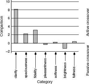
Figure 5.23 Active versus passive crossovers – subjective data (after Campbell)7
The results show a clear overall favour for the active crossover. The assessment of the extra brightness from the passive crossover could well be due to greater levels of non-linear distortion, which may in fact not be a result in its favour
Conversely, the list of benefits for the use of passive, high level crossovers for studio monitors would typically consist of:
1) Reduced cost? Not necessarily, because several limited bandwidth amplifiers may be cheaper to produce than one large amplifier capable of driving complex loads. What is more, the passive crossovers for the 1000 watt Kinoshita studio monitors shown in Figure 8.2(a) cost over 3000 euros each.
2) Passive crossovers are less prone to being misadjusted by misinformed users, who think that crossovers are some sort of ‘adjust to taste’ tone controls. On the other hand, passive systems have a tendency to misadjust themselves with age.
3) Simplicity? Not really, because very high quality, passive, high level crossovers can be hellishly complicated to implement, not to mention the amplifiers which are needed to drive them.
4) Ruggedness? No, because the electrolytic capacitors (necessary for the large values) are notorious for ageing, and gradually changing their values.
However, it must be stated that in less demanding circumstances than studio monitor loudspeakers passive crossovers obviously have their appropriate applications, but the above lists highlight the benefits of active designs where the highest system performance levels are required.
Clearly, the advantages of active, low level crossovers completely eclipse those of passive, high level crossovers, yet it was only around the late 1980s that dedicated active crossovers began to be seriously used on large scale monitor systems. Prior art used stock electronic crossovers, and perhaps these caused some delay in the acceptance of totally active designs because they were usually made with fixed slopes on all the filter bands. This tended to necessitate the use of multi-band equalisers, many of which were of dubious sonic quality. It took some time before people generally began to accept the need to buy a specific crossover with a monitor system, which was relatively useless in any other application. There was still a mix-and-match mentality towards components parts, each of which was expected to function as a ‘stand alone’ device. Once attitudes like this become established it can be very difficult to introduce new concepts. In fact, it took a long time before self-powered, actively crossed-over small monitors could establish their place in studio use, but domestic resistance to their acceptance has been even more pronounced. Established practices die hard, and they can be remarkably difficult to change, even in the face of clearly superior technology.
In 2003 and 2004, Alex Campbell worked on a performance comparison between active and passively crossed-over domestic loudspeaker systems at the Institute of Sound and Vibration Research, in the UK. He had an identical amount of money to spend on each design. His findings were presented to an international conference of the UK's Institute of Acoustics.7 Even at this modest level of engineering, aimed at the retail price range of £400 – £500 (E600 – E750) per pair, the subjective assessment, made under ISVR control and using a panel of 30 subjects, came out heavily in favour of the active design. The results are reproduced in Figure 5.23, with the ‘clarity’ and ‘fidelity’ ratings being strongly in favour of the active designs, [probably also as a result of greatly reduced intermodulation distortion]. In fact, the only tendency for the passive design to show a more positive result than the active design was in ‘brightness’, which could perhaps be a result of higher non-linear distortion levels. Perhaps the only real block to the general acceptance of the superiority of active crossovers and multi-amplification in the world of domestic hi-fi is the fact that so many hi-fi enthusiasts want to select their own favourite amplifiers and loudspeakers as separate items, but this perhaps has more to do with human psychology rather than audio engineering. Also, of course, choosing your own system with future up-grades in mind, as extra money becomes available, is a fun part of building up a hi-fi system, and perhaps a necessity in some smaller studios.
5.7 Physical derivation of crossover delay
Crossovers are more than simple filters. As we have seen, due to the group delays which exist in filter circuits, the outputs of the various filter sections are time-shifted by virtue of the phase shifts which are inextricably linked to the roll-offs. The result is that when the outputs are re-combined, either electrically or acoustically, there are often non-minimum-phase response irregularities in either the amplitude or phase responses. Essentially, they cannot be corrected by analogue, electrical means. Digital crossovers can be made to provide summing outputs, but the sonic benefits are not necessarily worth the efforts. For example, digital crossovers, unless they employ high sampling rates, (96 kHz or more) may introduce limitations in such a way that would make it difficult to accurately monitor analogue or high sampling rate digital recordings. What is more, a three-way stereo crossover would require six D to A converters on the outputs, and two A to D converters if they were being fed from analogue sources. If these were to be of the highest quality (and in a high quality monitoring system they should be expected to be nothing less) the cost of the unit could be exorbitant. Using anything less than the finest converters would make a mockery of trying to monitor recordings made through the best converters. This subject is discussed further in the following section.
There is, however, an analogue means of deriving delays. The loudspeaker cabinets, themselves, can be stepped, or the different drivers can be mounted in separate enclosures which are then mounted at different distances from the listeners. These two systems are depicted in Figure 5.24, but care needs to be taken to ensure that diffraction effects do not become problematical due to the increased number of cabinet edges. Figure 5.25 shows how a composite system using direct radiating bass drivers and a horn-loaded mid/high frequency driver can compensate for the delayed output from the bass units. In this case, the ‘natural’ position of the high frequency voice coil is behind the coil of the bass driver. All of these means achieve the same result by delaying the high frequency signals with respect to the low frequency signals. The distances between the voice-coils of the different drivers can be further physically off-set to whatever degree necessary to compensate for the electrically derived group delays. Given the speed of sound at 20 degrees C, each centimetre that a driver is mounted behind another (relative to their voice-coils) would give rise to a delay of 29.4 microseconds. Ten centimetres would therefore give rise to a delay of 294 microseconds, which would be sufficient to reverse the polarity of a wave at 1.7 kHz. (Look again at Figure 5.6.) Incidentally, the voice coils are used as an approximate reference for the source of the sound propogation because even though the diaphragms are ahead of the voice coils there is a finite time of propogation from the coil to the diaphragm face which, with most loudspeaker constructions, is roughly of the same order as the speed of sound in air.
5.8 Digital crossovers
As time passes, digital crossovers have become more commonplace in professional loudspeaker systems, although their use in domestic circumstances is still largely restricted to home recording facilities. They are particularly attractive because of the easy implementation of almost any amplitude response, phase response, signal delay, driver compensation and even room compensation. However, all this flexibility comes at a considerable cost.
Sonically, in terms of ‘hi-end’ hi-fi or high resolution studio monitoring, the highest fidelity can only be achieved if the sample rate and bit rate used in the crossovers at least equal those of the recording medium, or exceed the resolution of the ear and produce no audible artefacts. It may be difficult to hear the difference between a 20 bit/96 kHz recording and a 24 bit/192 kHz recording when listening to a crossover based on 16 bit/48 kHz processing. Even if a crossover has internal processing which seems higher than necessary, the resultant output after signal manipulation has taken place may not be as great as the marketing figures would suggest.
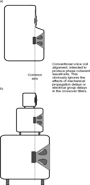
Figure 5.24 Methods for the physical compensation of propagation delays a) The stepped baffle. b) Separate boxes
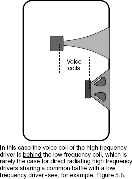
Figure 5.25 Flat baffle with a horn-loaded high frequency driver
In many cases it is possible for horn mounted compression drivers to align themselves very closely to the ideal whilst sharing a common, flat fronted baffle with a low frequency driver when the electrical group delays of the crossover filters are also taken into account, especially when steep-slope crossovers are used
The main problem, however, is concerned with the converters. As the finest amplifiers are still of the analogue variety, D to A (digital to analogue) conversion must take place in each output of the crossover, and, for either professional monitoring or ‘high-end’ high fidelity, these crossover D to As must be of higher resolution than any other part of the signal chain. If they are not, then they will limit the quality and the resolution of the chain. As with the power amplifiers and loudspeaker cables (which will be discussed in the next chapter) the splitting of the frequency bands does offer some respite from the demands of handling the full audio bandwidth. Nonetheless, to achieve the highest levels of sonic quality, D to A converters are expensive, and a stereo, three-way digital crossover would require six of them. At the time of writing, and whilst analogue power amplifiers are the general order of the day, it would be reasonable to expect to pay 3000 to 5000 euros for those six converters. If analogue inputs were required, then the A to D (analogue to digital) converters may add another 1000 euros or so to the price of the crossover if the equivalent quality was to be expected.
Under less critical circumstances, digital crossovers can be very useful tools, but when they are user-programmable, they run the risk of being inappropriately applied. One must be very careful when trying to ‘solve’ amplitude/phase problems that the solutions do not go against the laws of nature. Straightening out the phase associated with an amplitude roll-off may be very tempting, especially where the application is at the extremes of the frequency bands, but the results can sound unnatural because they are unnatural. On the other hand, in concert sound applications, where subtleties are by no means as important as solving the normal problems faced by such events, digital crossovers have been an enormous step forwards. Their real drawback is their cost when they must operate at the highest levels of sonic transparency. In many such cases, analogue crossovers may simultaneously be simpler, cheaper, more robust, and better.
References
1 Theile, A. N., ‘Loudspeakers in Vented Boxes’, Part 1, Journal of the Audio Engineering Society, Vol 19, No 5, pp 382–392 (1971)
2 Theile, A. N., ‘Loudspeakers in Vented Boxes’, Part 2, Journal of the Audio Engineering Society, Vol 19, No 6, pp 471–483 (1971)
3 Small, R. H., ‘Vented Box Loudspeaker System’, Journal of the Audio Engineering Society,
Part I, ‘Small signal analysis’, Vol 21, No 5, pp 363–372 (1973)
Part II, ‘Large signal analysis’, Vol 21, No 6, pp 438–444 (1973)
Part III, ‘Synthesis’, Vol 21, No 7, pp 549–554 (1973)
4 Small, R. H., ‘Closed Box Loudspeaker Systems’, Journal of the Audio Engineering Society,
Part I, ‘Analysis’, Vol 20, No 10 (1972)
Part II, ‘Synthesis’, Vol 21, No 1 (1973)
5 Small, R. H., ‘Passive Radiator Loudspeaker Systems’, Journal of the Audio Engineering Society,
Part I, ‘Analysis’, Vol 22, No 8 (1974)
Part II, ‘Synthesis’, Vol 22, No 9 (1974)
6 Small, R. H., ‘Direct Radiator Loudspeaker System Analysis and Synthesis’, Journal of the Audio Engineering Society, Vol 20, No 5 (1972)
7 Campbell, A. M., Holland, K. R., ‘Active vs Passive Crossovers for Mid-Priced Hi Fi Loudspeakers’, Proceedings of the Institute of Acoustics, Vol 26, Part 8, pp 116–123, Reproduced Sound 20 conference, Oxford, UK (Oct 2004)
Bibliography
1 Colloms, M., ‘High Performance Loudspeakers’, 6th Edition [Chapter 6], John Wiley & Sons, Chichester, UK (2005)
2 Borwick, J., ‘Loudspeaker and Headphone Handbook’, Third Edition [Chapters 5 and 6], Focal Press, Oxford, UK (2001)