
Chapter 12
The challenges of surround sound
The choice of loudspeakers for use with surround-sound systems is never easy. One problem is that the concept of surround means so many different things to so many different people. Except for professional cinema applications, where Dolby and THX, along with a few other companies, have laid down strict guidelines, the rest of the world of surround exists in near chaos. Even in professional, industry magazines, recording engineers and producers, who ought to know better, can be seen promoting the idea that there are no rules, so everybody should do it in their own way. Well; if there are no rules in the studios, then where are the references for the domestic reproduction systems to comply with?
The majority of this confusion stems from the fact that modern, music-only surround sound was never conceived and controlled purely by the music business, but has developed as an adjunct to other surround technologies which have developed for their own purposes, and which were never primarily intended to be capable of audiophile quality music reproduction. Exactly how best to deal with the subject of the recording and reproduction of music in surround is something which is still very controversial; even in professional circles.
In domestic applications, we have to accept that in the majority of cases one loudspeaker arrangement will be used for home cinema and the reproduction of music-only SACDs and DVDs in surround. This is a very unsatisfactory situation, but it would be totally unrealistic to expect people to have ten or more loudspeakers in their lounges. Firstly, therefore, it may be beneficial to look at the reasons for the undesirability of the above circumstances by looking at a range of professional surround mixing circumstances. This will also establish a more global understanding before embarking on a more detailed discussion of the requirements of each individual loudspeaker.
12.1 Surround sound in professional studios
Surround sound, in the guise of quadrophonics, first came to prominence in the early 1970s. The concept of the use of close-field monitors had not yet become widespread, so the first quadrophonic control rooms tended to consist of the two front halves of the then normal stereo control rooms placed face to face. A 1970s-style quadrophonic room is shown in Figure 12.1. There was some pressure at the time to spell the word quadraphonic, with an ‘a’, which was said to be more etymologically correct, but the compatibility with stereophonic and monophonic led to a tendency to use the ‘o’ spelling. However, when The Who released their famous film Quadrophenia, that seemed to kill off the ‘a’ spelling. It was in such uncertain conditions and the battles of the format wars that quadrophonics sprung into life.
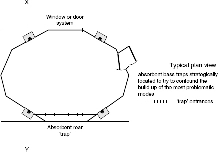
Figure 12.1 A quadrophonic control room from the 1970s
In effect, the room consists of the two front walls of a stereo room placed face to face. Note that the front loudspeakers are flush-mounted, above the windows, but the rear loudspeakers are mounted above the soffits of the machine alcoves – another source of asymmetry
In those days, quite frankly, the sound in most cinemas was bad. Dolby, to their great credit, began to specify that cinemas which used the Dolby processed soundtracks should comply to certain standards. Dolby understood the limitations of the phase-matrixed quadrophonic music systems, (which were not convincing the record-buying public to purchase many quadrophonic music systems) but they saw the possibilities of stabilising the centre-front image in cinema presentations by using one of the four quadrophonic channels in the centre-front position, effectively making a three-channel frontal stereo sound-stage. The remaining channel they fed to multiple rear and side loudspeakers, all supplied with the same signal, to give the effect of a distributed source of ambiental sound. This was the Dolby Stereo system. The quadrophonic and Dolby Stereo layouts are shown in Figure 12.2. Both systems used phase-matrixed analogue recordings, which exhibited very poor separation between channels, and ‘logic’ enhancement systems were usually employed to improve the inter-channel discrimination. (Some vinyl disc systems used high frequency carriers, for the rear channels, instead of phase matrixing, but they were fraught with problems.) The quadrophonic music systems of the 1970s used four identical loudspeakers, but the Dolby Stereo system required large loudspeakers of controlled directivity behind the screen, and multiple, small, restricted bandwidth, wide-dispersion loudspeakers for the surround channel, to maximise the audience coverage and the sense of spaciousness. Therefore, at this very first bifurcation, the loudspeaker requirements for four channel surround had already changed.
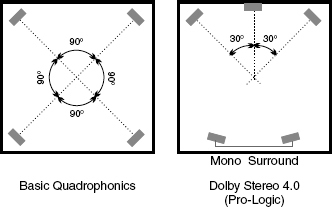
Figure 12.2 Comparison of quadrophonic and Dolby Stereo formats, both using four channel matrix-encoded signals
Around this time, still in the mid 1970s, Tomlinson Holman proposed, for domestic playback, the use of dipole (figure of 8) loudspeakers for the surround channels1. Even at this very early stage, many people were beginning to realise that the 360 degree distribution of primary instruments was not suitable for a great deal of music, and that the rear channels were often better employed for ambience. The use of dipoles in this position, as shown in Figure 12.3, with their nulls facing the listeners, ensured that only the sound that reflected from the walls would be heard, thus creating a well diffused ambient surround field.
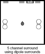
Figure 12.3 Dipole surround loudspeakers
Figure 12.4 shows a reasonably similar idea, proposed by Fosgate2, but using bipolar loudspeakers instead of the dipoles proposed by Holman. Again, the loudspeakers are generally facing away from the listener, and in the drawing each side of the surround uses 3 drivers – a pair in the side cabinets and one in the rear cabinet. There was also in the proposal a means of creating four channels from the rear pair, in order to further diffuse the ambience. In the above configuration there are no true nulls, as there are in Figure 12.3, but only the low frequencies will radiate directly to the listener. The middle and high frequencies will tend to be received via reflexions only.
Another attempt at providing a diffuse side/rear surround field is shown in Figure 12.5. This method has been used in small film dubbing and video post-production studios3. In this case the conventional box loudspeakers are mounted so as to face mathematically derived diffuser panels which are fixed to the walls. Once again the low frequencies will radiate omnidirectionally, but the middle and high frequencies can only arrive at the listening position via the diffusers. A variation on this theme, using naturally diffuse sources, is shown in Figure 12.6. This system uses distributed mode loudspeakers as single surround sources on each side wall4. Figures 12.1 to 12.6 clearly show how professional and domestic systems have both developed around concepts which have used some very different types of loudspeakers to try to create the desired illusion. Unfortunately, with so many concepts in use – and we have barely begun discussing them – it should already be apparent that compatibility problems are to be expected between the mixing and domestic playback environments.
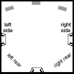
Figure 12.4 Bipolar surround, proposed by Fosgate, using processors to decode seven channels processed from five
Figure 12.5 A five-channel format using wall-mounted diffusers to disperse the sound from the conventional rear loudspeakers. (After David Bell)

Figure 12.6 Diffuse surround sources – NXT DML panels
In cinemas, the environments are usually well controlled, in order to conform to standards which ensure reasonable commonality with the dubbing theatres – the studios in which the film soundtracks are mixed. Although this book is not intended to be about cinema and video systems, it is necessary to look at them here so that their influence on the development of domestic entertainment systems can be better understood. For many people, since the beginning of the 21st century, the playback of music recordings in the home has only been via their home theatre systems, which are primarily geared to the reproductions of film and video soundtracks, but it must be clearly established that there is no single type of loudspeaker which can serve for all purposes. The monopoles, dipoles and bipoles represented in Figures 12.2, 12.3 and 12.4 are fundamentally different radiating sources, as are the diffuse sources shown in Figures 12.5 and 12.6, and the T.V./video style systems shown in Figure 12.7. There is no possibility of these diverse sources producing identical sounds. Consequently, if music is not mixed on systems of the same general concept as the reproduction systems, then the reproduction cannot be anything other than compromised. The resulting sound may be pleasing, and may even be desirable, but it will not be ‘high-fidelity’ in the sense that a good domestic stereo system, well positioned in an appropriate room, will be expected to radiate a sound which is very close in its balance and timbre to that which was being heard by the recording personnel at the time of mixing. With surround sound, the variables are so many that the degree of fidelity which we have come to expect in stereo is rarely achievable.
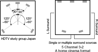
Figure 12.7 Incompatible domestic formats
12.2 Cinema sound
Feature films, in general, are mixed specially for the big screen, where there is an important psychological correlation between picture size and the appropriate sound pressure level. Figure 12.8 shows a behind-the-screen installation of a mixing room (dubbing theatre) equipment for either 5.1, 6.1 (Dolby EX, with left, centre and right surround channels) or 7.1, the Sony Dynamic Digital Sound (SDDS) system. The surround loudspeakers are 12 JBL 8340A cabinets, specially designed for use as cinema surround loudspeakers. A smaller 5.1 room, using JBL behind-screen loudspeakers is shown in Figure 12.9. Rooms such as these are used for the final mix, usually from ‘stems’ (or pre-mixes) of music, dialogue and effects. In many cases, however, the music is mixed in smaller rooms without screens. Such a room is shown in Figure 12.10. This room has a large, Quested frontal monitor system in a room designed by Sam Toyashima. The surround loudspeakers are pairs of smaller Genelec monitors, on pedestals, in an L-shaped, side and rear configuration. The monitor system is essentially flat, with a small high frequency roll-off in typical music recording studio style.
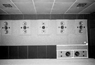
Figure 12.8 A cinema studio monitor wall for Sony SDDS 7.1 surround
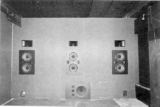
Figure 12.9 Auditel ‘Audi A’, in Paris, France, using a JBL cinema system
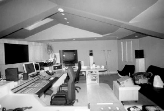
Figure 12.10 The ‘Kyoto’ control room at Eurosonic, Madrid, Spain, designed by Sam Toyashima. The room is used for mixing stems for film soundtracks. The surround loudspeakers are pedestal mounted at the sides and rear of the room. The large, right-front monitor is the black rectangle at the left of the photograph. The console-mounted loudspeakers are for stereo television mixing
Once the music stems go to the dubbing theatres to be mixed with the dialogue and effects, the surround/front balance will be readjusted to the cinema environment. What is more, the overall sound will be re-equalised, because after the perforated projection screen has been placed in front of the loudspeakers, the response at the mixing positions is adjusted to the ‘X-curve’, as shown in Figure 12.11. Mixing will normally take place with peak levels reaching 105 dBC or more at the listening position. A picture of a life-sized tank, firing a shell with a ‘bang’ at 85 dBC would simply not sound credible, so large sounds go with large screens. Bearing in mind that when played in the home on a small screen, even 85 dBC may be considered to be too loud for the neighbours, a quick glance at the equal loudness curves shown in Figure 8.4 will reveal that the perception at 80 dB and 100 dB is quite different. Film protocol demands that the mix be done at the same level as the cinema presentations, so that the perception of relative frequency balance can be accurately assessed, unlike the music mixing process, where no such control exists. For home cinema release, the soundtrack may have to be re-equalised, not only because of the lower probable level of reproduction, but also because many home systems do not reproduce with an X-curve equalisation. (For more on the X-curve see the Glossary).
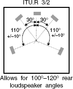
A typical domestic playback system is shown diagrammatically in Figure 12.12, conforming to the ITU775 recommendation. When a film is played back on such a system, using loudspeakers of typical domestic nature, the overall perception is bound to change because the type and distribution of the loudspeakers are different to those on which most films are mixed. Very little source material is therefore specifically mixed for reproduction on home theatre systems. In audio-visual presentations, the changes in the perception of the soundtracks tends to be compensated for by the strong domination of the eyes over the ears. The small screen also tends to require less low frequencies in the sound. However, when we listen to music-only mixes, there are no such distractions, and the lack of fidelity can be conspicuous.
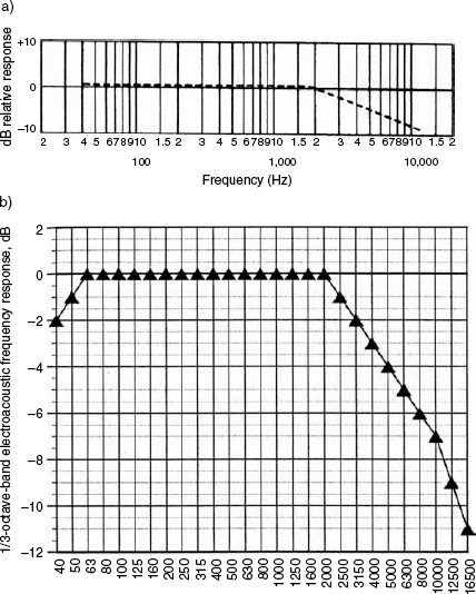
Figure 12.11 The X-curve. a) ISO Bulletin 2969 – recommended response curve for motion picture loudspeaker systems. b) The X-curve for cinema monitoring, to be measured spacially averaged in the far-field of the sound system with quasi-steady state pink noise and lowdiffraction (small) measuring microphones. The room volume must be at least 200 m3 (6000 cubic feet). The curve is additionally adjusted for various room volumes, as per SMPTE 202
12.3 Music mixing
Unlike in the cinema world, no standard mixing conditions have ever been enforced for music mixing, and recommendations have been ignored in the majority of instances or, at best, have only been respected in certain aspects. There has been a free-for-all which has continued unchecked largely because the domestic surround sound systems have been predominantly cinema/video orientated, and music mixes have been accepted in a compromised form by people who were unwilling to accept a separate, music-only system at home. The lack of any clear domestic trends of high fidelity music orientated surround systems has not encouraged recording studio owners to invest in specialised surround-sound mixing facilities, so the studios, themselves, are therefore tending not to give any clear leads. In many cases there have been few clear-cut decisions about whether music should be mixed four-channel, five-channel, or five-channel plus a discrete low frequency channel. (5.1 as it was dubbed by Tom Holman.) The argument for four channels has been put forward by many people who have felt that the centre-front channel is compromised in many 5.1 domestic systems, because of the conflict between the loudspeaker and the video screen vying for the same spot. Considering the fact that the centre-front in music mixes is the location for many lead vocals and primary instruments, the risk of compromising it has led many music mixers to continue to make phantom centres from the front left and right channels to avoid the risk of the mix being ruined by playback through systems with inadequate centre channels. In most cases, the front left and front right loudspeaker will, indeed, be the best loudspeakers in any set up.
Another body of opinion has been avoiding mixing vocals in the centre channel because of the equalisation changes which are noticed if the recording is ‘folded down’ to four or two channels due to the asymmetrical or symmetrical reception by the ears of a phantom centre or discrete centre image respectively. The problem is shown in Figure 12.13, from which it can be seen how the signals arriving from 30 degrees either side of centre front suffer a path length difference of about 10 cm between the nearest and furthest ear from each loudspeaker. As discussed in Chapter 5, arrival delays between two drivers will give rise to a cancellation at the ear around the frequencies which arrive in the region of 180 degrees out of phase. Conversely, the sound from one loudspeaker will suffer the same cancellation effects if the ears are displaced so that the arrival of the wavefront is not simultaneous at the two ears. Consequently, a phantom centre image will suffer from some cancellation in the region of around 2 kHz. When making decisions about equalisation of the phantom centre-front instruments or voices, this dip is automatically taken into account. When listening to the same sounds through a discrete centre-front channel, no such arrival delay dip occurs, so, for any given sound, the equalisation decisions would be different when mixing with a discrete or a phantom centre. This has led some people to complain that the sounds which they are accustomed to recording and monitoring via a stereo pair of loudspeakers sound too present when monitored through a discrete, centre-front loudspeaker. They therefore opt to use phantom centre-front images in order to try to maintain better equalisation compatibility when the surround mixes are heard in normal, two-channel stereo.
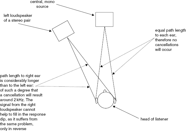
Figure 12.13 Path length anomalies for phantom central images
The other big dilemma is often whether to mix to 5 or 5.1 channels – that is, with or without the sub-woofer as a dedicated channel. In reality, the sub-woofer channel has little to do with music mixing. The .1 was a cinema invention to provide extra headroom for low frequency effects, such as during explosions. In music, there is really no equivalent function, so five-channel mixing tends to be the norm. When listening to a ‘pseudo 5.1’ system which is really a five-channel system with a bass management system feeding a common sub-woofer, there will be perceptual differences as compared to listening on five full-range loudspeakers, due both to the mono low-bass and to the arrival time anomalies that will be experienced in all but the very centre of the array. The perception will also be likely to change significantly with changes in the frequency below which the content of the five channels was filtered and sent to the sub-woofer. There is no standard frequency of cross-over into sub-woofer(s).
12.4 Sub-woofers – discrete and managed
To get the best out of any sub-woofer, the cabinet needs to be large. The sub-woofers shown in Figure 12.8 are real sub-woofers, designed to outperform even the 600 litre cabinets of the five main loudspeaker systems, which easily reach down to 20 Hz themselves. With ten 15 inch loudspeakers in the five 600 litre cabinets, and with reflex ports tuned to 20 Hz, the low-frequency output of this main system, alone, is quite prodigious. Each of the sub-woofers visible in the photograph consists of a McCauley 6174, eighteen inch driver (460 mm), with a free-air resonance of 20 Hz and a sensitivity of 94 dB for one watt (2.83V) at one metre. The frequency range is quoted by the manufacturers as 15 Hz to 800 Hz and the rated power capacity is 800 watts. The boxes are also of 600 litre capacity, with one driver in each box, and are reflex tuned to 16 Hz. They are constructed from a sandwich of 2 layers of 19 mm chipboard with a 5 kg/m2 plasticised bituminous deadsheet in-between, and lined with a sandwich of 20 mm felt/3.5 kg deadsheet/20 mm felt. The boxes are also internally braced in all three axes, and are surrounded by 10 cm of concrete. The 40 mm-long voice coil allows a cone travel in any one direction of 15 mm under a constant force factor (Bl), and a 25 mm unidirectional travel with reduced Bl before mechanical limitations arise. The total cone excursion can therefore reach 50 mm (2 inches) peak to peak. Each drive unit weighs over 16 kg, and the ferrite magnet alone, of 13000 gauss, weighs almost 12 kg, and has a Bl factor of 15.3 tesla.
This system is being explained in detail because it is a professional sub-woofer, intended to deliver high quality sound at cinema levels, day after day, year after year. The response decay is rapid and uniform in the frequency bandwidth of use. The loudspeakers have no characteristic ‘boom’ to their sound. Their positioning at the junction of the front wall and the floor effectively mounts them in quarter space (or space) as explained in Chapter 7. This effectively raises the sensitivity by 6 dB compared to the quoted 94 dB in free space. The use of two drivers, side by side, increases the loading on the cones still further, and the mutual coupling so achieved adds another 3 dB to the low frequency sensitivity, yielding 103 dB for 1 watt at 1 metre for the pair of cabinets. Structural losses are kept low by making both the floor and monitor wall out of thick concrete. The listening distance in this room is about 8 metres, so the ‘double distance rule’ (stating that the SPL falls by 6 dB every time the distance from the source is doubled, [see Chapter 7]) would mean that 103 dB at 1 metre would fall by 18 dB at 8 metres, to 85 dB. Each multiplication of the power by 10 adds 10 dB to the SPL, so 1000 watts (10 × 10 × 10) would deliver 30 dB more than the 85 dB for 1 watt. The maximum peak short-term SPL to be expected on rare occasions in cinema would not exceed 115 dBC, so the 1600 watts rms rating of the pair of loudspeakers (or 3200 watts for 10 milliseconds) gives the system adequate damage tolerance. At all normal cinema levels, the loudspeakers are working well within their low distortion range, and, as high level peaks are always short-lived, thermal compression is not a factor. The amplifiers driving the sub-woofers are Class AG, made by Neva Audio in St Petersburg, Russia, and can deliver 2000 watts into 8 ohms. The above description outlines the lengths that one needs to go to outperform the low frequency response of a good, medium to large sized studio monitor system.
Purely in terms of high fidelity, when mixing music in surround on a monitor system using five, full-range loudspeakers, it is best to use their own low frequency capability rather than a separate sub-woofer, because the five discrete sources can give better spacial perception, a seamless response because no low frequency crossover is involved, a tighter and better spacially distributed transient response, and an overall low frequency sound quality that outperforms the majority of commercial sub-woofers. In fact, in many studios which are used to mix music stems for cinema, and where some low frequencies may be mixed to a separate sub-bass (Low Frequency Effects [.1]) channel, the low frequency feed is often distributed across the flush-mounted front loudspeakers, instead of feeding a discrete sub-woofer of commercial design, precisely because the LF response of the main system is likely to be better than that of a commercial sub-woofer. However, as will be discussed later, there are other concerns which may lead to other decisions about the best option for mixing formats.
There can also be some confusion caused by the different meanings of LFE as have been applied to sub-woofer use. In the Dolby Digital (Dolby Surround) language, LFE stands for the Low Frequency Effects channel that is the discrete (.1) channel of low bandwidth, used in addition to the 5 main channels. Conversely on many music monitoring systems, the LFE is the Low Frequency Extension provided by the sub-woofer, whose feed is derived from a bass management system which re-directs to the sub-woofer the low frequency content of the five principal channels, below the frequency where the five main loudspeakers begin to roll-off in their frequency response. The two concepts are very different. In the former case, the five main channels are full range, and the LFE channel may at times operate up to 500 or 1000 Hz, although normally the upper limit is more likely to be around 120 Hz. In the latter case, the sub-woofer should ideally only operate below 80 Hz, or the low frequencies will be localised by the ear to the position of the sub-woofer. A further concept of Low Frequency Enhancement also exists, in the form of an optionally reproducible low frequency effects channel for digital television, but whose content is not essential to the overall programme. We therefore have LFE standing variously for Low Frequency Effects Extension, or Enhancement. There is little or no commonality between the three concepts, and some implementations are optional. So much for standardisation.
Dolby now recommend a sub-woofer distribution for cinema use as shown in Figure 12.14, with one woofer placed 33% of the distance from one side wall, and the other woofer placed 20% of the distance from the other side wall. This gives rise to a more or less central image, without either risking the localisation of the effects channel to one side of the cinema or symmetrically driving the room modes from a central location. However, in home use, one single sub-woofer is normally used whose frequency response is limited by a crossover, the frequency of which is determined by the low frequency response of the five main loudspeakers. Somewhat absurdly, this can be as high as 400 Hz when used with mini-satellite loudspeakers. In such cases, localisation of many low frequency sounds to the ‘sub’-woofer in inevitable. For discerning listeners, the crossover to a sub-woofer must be kept below 80 Hz, and lower if possible, or spacial information will be lost and localisation of sound to the sub-woofer will occur. [However, see Section 12.6.]
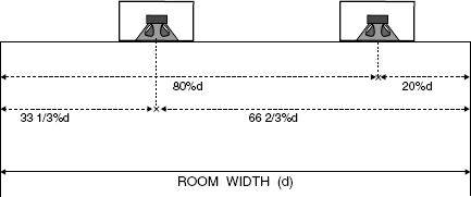
Figure 12.14 Sub-woofer siting for cinema installations
Dolby recommendations for siting two sub-woofers; one of them one fifth of the room width from one side wall, the other one third of the room width from the other side wall. This not only avoids both the localisation of the sound to a single sub-woofer placed off-centre, but also avoids the symmetrical driving of the strongest room modes by the central placement of the sub-woofer(s)
Obviously, when we listen to five discrete channels we localise sounds at their sources, but a system with a bass management system will re-distribute the low frequencies, sometimes with odd consequences. For example, a synthesizer located in the left rear loudspeaker may sound strange if its output above 200 Hz comes from the left rear and the output below 200 Hz comes from the front-located sub-woofer. Again, this may in many cases sound acceptable, but it is not high fidelity inasmuch as this was probably not what the music producer intended. However, some mixes are actually carried out with bass management systems because some mixing personnel feel that this is more typical of how the majority of people will listen at home. This is a market-led approach, rather than a high fidelity approach, but there will be justification for this idea in Section 12.6, on grounds of sheer practicability.
12.5 Size versus performance compromises
The low frequency decay of a good studio loudspeaker system is shown in Figure 12.15. The response extends quite low, and the decay is fast and uniform with frequency. In general, such a response is only possible with relatively large boxes, but compactness has been a very desirable characteristic of loudspeakers for surround systems, because the domestic practicality or social desirability of placing five or six large cabinets in a dwelling space is not good. Even in professional studios, the lack of universally accepted surround formats for music mixing has made owners reluctant to invest heavily in surround control rooms. For this reason, many stereo rooms have been adapted for surround use by the installation of free-standing systems. Again, for reasons of practicality in rooms already containing much other equipment, many studios have opted to use rather small loudspeakers.
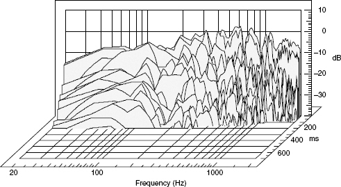
Figure 12.15 Responds decay of a full-range loudspeaker in an acoustically well-controlled room
A single sub-woofer must handle the low frequencies from five channels, and so needs to have the same acoustic output capability as that of all five principal loudspeakers connected in phase and receiving the same signal. By its very nature, a sub-woofer is required to have an extended low frequency response, but to achieve this in a small box with the sensitivity necessary in order not to burn up with the sheer electrical input power needed to handle the combined output of five channels is, as we saw in Chapter 11, a great conflict of requirements. The sensitivity problem has been addressed by some manufacturers by the use of bandpass cabinets and horn loaded cabinets, but each only addresses part of the overall response shortfall.
The bandpass concept was described in Chapter 3. These systems tend to exhibit multiple resonances, as it is the resonant effects that help to augment the sensitivity and flatten the pressure amplitude response over the desired band. The response of one such cabinet is shown in Figure 12.16. The waterfall plot shows a flat response for just over an octave, but the decay shows a degree of resonance that would not be conducive to tight, high-impact bass sounds. The step function response in the same figure shows just how slow the attack is. The response actually builds up with time, rather than immediately starting to decay. Neither the attack nor the decay could really be deemed to be concordant with the concept of high fidelity.
Figure 12.17 shows the response of a horn-loaded cabinet intended for use as a sub-woofer. Typical of the high acoustic loading presented to the diaphragm by the horn, the time response is characterised by a fast attack, as shown in the step function plot, and a fast decay which is clearly observable in the waterfall plot. Unfortunately, the bass extension is rather poor because the horn mouth needs to be proportionate to the wavelength in order to couple the horn to the room, as explained in Chapter 4. Once again, when size is kept small, we have a trade off between bass extension and a clean transient response. Therefore, a small, high-fidelity, high sensitivity sub-woofer is a contradiction in terms. ‘Woofer’, perhaps, but sub-woofer only if a low fidelity transient response can be tolerated. A horn-loaded loudspeaker which is a true sub-woofer is shown in Figure 12.18, but small it is not. Nevertheless, in some cases, the corner placement of a horn-loaded sub-woofer may go some way to extending the low-frequency output, but it will exite all the possible room modes, and hence may provoke severe room resonances. This would, of course, defeat the object of using the loudspeaker with the better transient response.
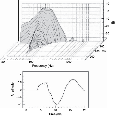
Figure 12.16 Waterfall plot and step-function plot of a typical bandpass sub-woofer in an anechoic chamber
The need for small size in order to be marketable has led to an emphasis on the multichannel spacial sensations, and relatively little has been openly discussed about the ways in which many loudspeaker performances have dropped vis-à-vis older loudspeakers intended for stereo. There is a tendency for surround to compromise absolute fidelity for the extra sensation of space, but the excitement of the spaciousness can be short lived once the absolute fidelity loss is recognised. Loudspeaker manufacturers are obviously going to make what they can sell, and if super hi-fi surround systems appeal to only a very small market, then the bigger market will be primarily catered for. There has been a general recognition that the vast majority of domestic users will use ‘satellite and sub-woofer’ systems, and much effort has gone into finding means by which the low frequency cabinets can be positioned and controlled in order to get a real improvement in the LF response, even beyond that which could be expected from good stereo loudspeakers in the same rooms. This concept will be further explored in the next section.
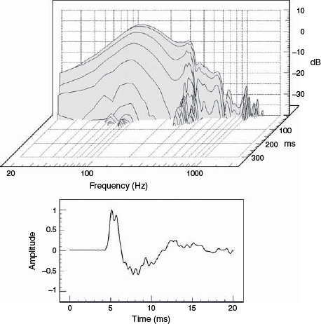
Figure 12.17 Waterfall plot and step-function plot of a horn-loaded sub-woofer in an anechoic chamber
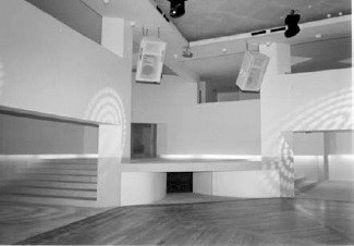
Figure 12.18 A concrete horn, under the stage, loads a cabinet with four 18 inch (450 mm) low frequency drivers. The response is essentially flat down to 20 Hz, and 120 dBC on the dance-floor is achieved with ease and reliability. The mouth size is 4 m × 1m
12.6 Compound sub-woofers and electronic control
Whilst no electronic signal processing system can be expected to outperform the excellent acoustic treatment of rooms, it is entirely justifiable to recognise that good rooms are expensive and rare. For this reason, some loudspeaker manufacturers have seen a real need for a means of deriving a decent low frequency performance in acoustically poor rooms, and the use of separate (sub-) woofers can be a real advantage in such circumstances as exist in many domestic listening rooms. Toole gave a good overview of the situation in his 2003 paper, ‘Art and Science in the Control Room’5. He made the observation that below about 100 Hz, room resonances can be controlled electro-acoustically, although response dips cannot be equalised. Between about 100 Hz and 300 Hz, mounting geometry, adjacent boundaries, and strong solitary reflexions can cause problems that defy simple electronic cures, and most probably need to be dealt with acoustically. Above 300 Hz, the loudspeaker dominates, so there is no substitute for using good, well-mounted drivers here.
Below 100 Hz, in small rooms, such as many sound control rooms and domestic listening rooms, the number of resonant modes will be few, and mostly well separated. This gives rise to great spacial variation and amplitude response variation. A listener seated at an antinode of a resonance will hear a greatly augmented response, whereas at a node the response would be diminished, perhaps almost to the point of cancellation. The perceived frequency response of a loudspeaker driving the room from a boundary would therefore be dependent upon the listening/receiving position. Conversely, a loudspeaker placed at a node of a resonance would be incapable of driving the mode at that frequency, whereas when placed at an antinode it would strongly drive the resonance. Hence, any given loudspeaker in any given room being measured or listened to at any given point in the room would exhibit a low-frequency response which was entirely position dependent, and likely to vary wildly from place to place unless the room was heavily damped, i.e. acoustically dead.
Back in the days of mono recording it was customary to find a loudspeaker position which drove a room in the most uniform manner achievable, and then find a listening position with the flattest overall response. Stereo complicated matters, because the relationship between the driving and the listening positions was fixed by the ideal equilateral triangle which needed to be maintained between the two loudspeakers and the listener(s). Finding three relatively flat positions was much more difficult than finding just two, especially when the three needed to maintain the equilateral triangle geometry. The extra degree of difficulty led to the development of highly specialised design concepts for stereo control and listening rooms, some examples of which are shown in Figure 12.19. All of the rooms shown are asymmetrical from front to back: the end that generates the sound is in all cases acoustically different from the end which receives the sound. This works fine for stereo, but for multichannel surround sound, where the rear channels may carry significant programme information, and not just ambience, this approach will not suffice. Dr Toole argues that in anything but very highly damped rooms with enormous bass absorption systems, the ability to obtain a flat low-frequency response from five full-range loudspeakers is beyond us. In fact, the authors of this book came to a similar conclusion in a 2004 conference paper, when discussing the concept of how to make a symmetrical room for surround sound with individual loudspeaker responses as good as can be achieved in a stereo room, especially with flush-mounted monitors6.
Toole is convinced that the five full-range loudspeaker option, when used below 80 to 100 Hz, can only lead to appalling bass responses in anything other than anechoic chambers, especially when one considers all the possibilities of the combinations of loudspeakers which may be radiating simultaneously whilst supporting some of the many possible phantom sound stages. He maintains that the bass summation is not only a cost-saving measure, but is a superior way to reproduce bass in non-ideal rooms.
Given this concept of mono bass below 80 Hz, a technique for achieving a flat, in-room response already exists, with the use of a combination of four distributed sub-woofers whose responses are modified by signal processing and parametric equalisation, both in the form of individual equalisation and global equalisation. This can bring an overall loudspeaker/room response to within about 3 dB of flat over a wide listening area. Moreover, the fact that room modal responses, as opposed to reflexions, are of a minimum phase nature, this amplitude correction will also tend to correct the phase, and hence the time response. Toole has been most insistent that this is the only practical solution for domestic surround sound listening, and, as such, it only makes sense to monitor the same way in the studio control rooms, because almost nobody will hear the mixes reproduced in a totally discrete way. On the other hand, Holman7 has argued that stereo sub-woofers can be essential in order to create a greater sense of spaciousness, and advocates the positioning of a sub-woofer half way down each side of the room. The authors of this book agree with both of them, hence the title of their aforementioned 2004 paper – Surround Sound – The Chaos Continues6. Spaciousness and flatness cannot both be maximised in the same system; except, of course, in an anechoic chamber!
Shortly before the publication of this book, Floyd Toole published a paper in the Journal of the Audio Engineering Society in which he expanded further on the concepts of low frequency responses for surround systems8. Dr. Toole has said that in his opinion, if room modes can be actively suppressed by processed multiple woofers, and a relatively flat, uniform, low frequency sound field can be achieved in less than perfect rooms, then achieving this in mono below 80 Hz may well be significantly more desirable than the extra spacial effects of stereo low frequencies which must suffer modal irregularities. There is a lot of reason in what he says.
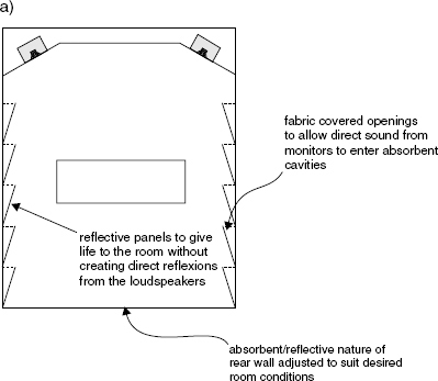
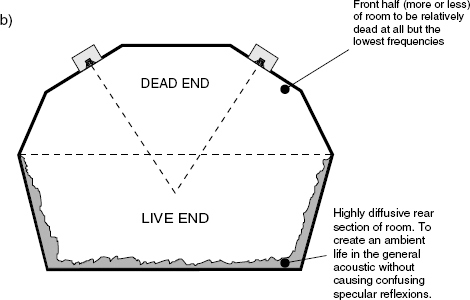
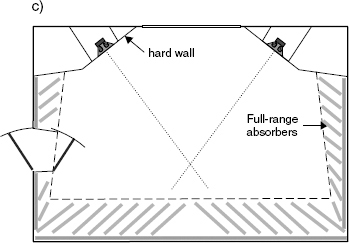
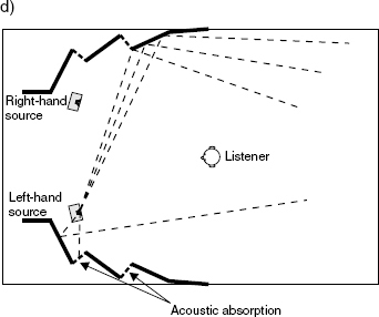
Figure 12.19 a) Typical room in the style of Wolfgang Jensen. b) Live-end, Dead-end control room. c) Non-environment control room. d) BBC-style, controlled reflexion room. e) Ishii/Mizutoni listening room. f) An IEC listening room
12.7 System considerations
What must be understood is that surround sound is not simply stereo plus another dimension. Surround sound is something totally different, and needs to be assessed as such. As we have already seen from Figure 12.19, the stereo rooms will not adapt well to discrete surround sound, although they can work quite well if the surround channels are restricted to ambience. This reappraisal of rooms for surround use, with careful juxtapositioning of diffusive and absorptive surfaces, evenly distributed around the room, also requires a reappraisal of loudspeaker performances. In many professional stereo rooms, the axial response of a loudspeaker tends to be paramount, because off-axis irregularities can, in many cases (although not all applications) be controlled by absorption.
However, in surround rooms, loudspeakers often tend to need to exhibit very smooth off-axis responses, because of the wider distribution of diffusively reflective surfaces in the room. They also need a wider directivity pattern in the horizontal plane because the listening positions tend to be broader than stereo listening areas. Figure 12.20 a) shows how a producer and engineer may experience essentially the same overall balance in a stereo listening room, but in surround, they may have to be side-by-side, otherwise the producer would remain too close to the rear loudspeakers. This is another argument for the use of the centre-front channel, because it can anchor the stereo centre image even for off-centre listeners, thus allowing two people to hear essentially the same mix when sat side-by-side. (However, there is also a good argument for larger mixing rooms, where small positional changes will less affect the perception!)
In Figure 12.20 b) the rear, P2 position is not valid because the person sitting there would hear too much of the rear channels in proportion to the front channels. The left side, P1 position would work reasonably well if the front sound stage was anchored with the central images coming from the centre loudspeaker. However, if a phantom central image were to be used, the person at position P1, would predominantly only hear it coming from the left loudspeaker, due to the precedence effect and the earlier arrival time of the signal from the left loudspeaker. (Unfortunately, this means that the decision whether to use discrete centre or phantom centre may be dictated by something as arbitrary as the size of the mixing room.)
The precedence effect, or the ‘law of the first wavefront’ means that for the arrival of two similar signals, varying in arrival time between about 1 millisecond and 40 milliseconds, the perceived direction of the source will be from the direction of the first sound to arrive, unless the level of the later arriving sound is 6 or 8 dBs higher. In reality, for a centrally panned image, the later arriving sound will also be lower in level, because it will be arriving from further away, so the directional pull to the earlier sound will be reinforced. Similar sounds arriving within less than about 700 microseconds (0.7 ms) will not be so affected, and sounds arriving more than about 60 ms apart will be heard as two separate sounds – a sound and its echo. There are ‘grey areas’ between 0.7 and 1 millisecond, and 40 and 60 milliseconds, which can depend on the nature of the signal and individual perceptions. For this reason, Dolby Digital Surround systems in cinemas have a delay, adjusted to circumstances, on the signals fed to the surround channels so that if any sound exists in all loudspeakers, then even for people at the back of the cinema, the behind-the-screen loudspeaker signals will always arrive first. This keeps the action located on the screen. However, the music industry does not apply such delays because the rear channels may be used for discrete instruments, and not just ambience.
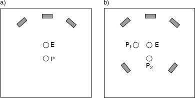
Figure 12.20 a) In a stereo room, given a suitably absorbent rear wall, the engineer and producer at positions E and P would hear essentially the same mix. The only significant difference would be a slightly reduced level at position P. b) In a surround room there are no positions where two people can hear the same balance. Relative to the engineer's position (E) position P1 would experience a left-heavy mix, and P2 a rear-heaving mix
Only large rooms can resolve this problem, but, ironically, the current trend is towards smaller rooms
What is more, in some cases, the cinema surround loudspeaker arrays are also tapered in level, becoming lower towards the back of the theatre. There will always be a level reduction from the frontal loudspeakers as a listener moves towards the rear, so a corresponding level reduction in the surround loudspeakers can help to prevent the surround sounds from dominating the more important screen sounds. A 4 dB taper from the frontmost to the rearmost surround loudspeakers is about the maximum which can be used before the surround distribution would itself become compromised. In the configuration shown in Figure 12.20 b), with only single loudspeakers on each of the rear channels, no such tapering would be possible, so the front/rear balance would depend upon the listening position. Room reflexions can help to ameliorate the problem, but smooth off-axis responses are essential if the reflexions are to be returned with an evenly distributed energy balance, or substantial colouration of the sound would be experienced.
For the above reasons it can be very difficult in small rooms to find positions where two or more people can enjoy similar listening experiences from surround sound systems, especially when the use of the centre channel has not been fully exploited for reasons of lack of faith in the end-users’ choice of adequate centre-front loudspeakers. In larger rooms, which allow greater distances between the loudspeakers, the relative time and level differences are generally less, so a larger area can usually be achieved where a more common listening experience can be realised. However, as always, when the distance from the loudspeaker to the listener is increased, the room acoustics come more into play. If the room acoustics cannot be changed, then loudspeakers may be chosen with more suitable directivity patterns, but this would, of course, also change the relationship of the direct to ambient sound. There are no easy solutions to problems of ‘universal’ surround sound.
Loudspeakers that are good for stereo are therefore by no means necessarily good for multi-channel systems. The loudspeaker directivities and total power responses need to be considered in relation to room acoustics and the size and orientation of the designated optimal listening areas. The question of whether five surround channels will be used for the free distribution of instruments or as a frontal stereo sound-stage plus ambient rear-channels is another factor which will greatly influence loudspeaker choice. Quite clearly, a system using monopole front loudspeakers with dipole rears whose nulls are facing the listeners will not be capable of giving equal reproduction perception to a guitar, for example, panned from one type of loudspeaker to the other. Conversely, a symmetrical system which can do this may be unable to exhibit the same enveloping ambience as the dipole. When considering true high fidelity in surround sound, the choice and the positioning of the loudspeaker is greatly more complicated than the corresponding choices in stereo.
Unfortunately, it is also the case that very few studios are as well prepared for surround as they are for stereo, and the people doing the surround mixes are generally much less sure of what to do, which is not surprising when surround can mean so many things to so many different people. Some, who perhaps should know better, even applaud the free-for-all, no rules approach in the name of artistic freedom, but, as was mentioned in the opening paragraph of this chapter, if there is no reference standard at the time of mixing, then how are the domestic listeners to know what loudspeaker arrangement is most appropriate to reproduce the intended sound of any given mix?
The range of loudspeakers which are currently used in the control rooms where music surround mixing takes place is wildly variable, as are the control room acoustics. There is no degree of standardisation even vaguely approaching that of film dubbing theatres, and no companies such as Dolby or THX to ‘enforce’ the standards. As previously explained, rooms which are optimised for stereo are not optimal for surround, and loudspeakers which are optimal for use in good surround use may not be optimal for stereo. Mixes done for cinema are not optimally reproducible on domestic surround systems which are optimised for music, and vice versa. Music which has been mixed on five, discrete, full-range loudspeakers will not be optimally reproduced on ‘home theatre’, bass managed systems. High fidelity music-only surround and home cinema systems are very different. This is both unfortunate and disappointing, because very few people will be prepared to purchase, or live with, two completely separate systems. However, for people who are happy to listen to all their music via MP3 coding perhaps this discussion about surround loudspeaker optimisation is superfluous, yet unless there is a public demand for quality, the industry will stagnate, and the whole artistic process of music production will be demotivated such that creativity will surely suffer. The lack of general awareness about the whole question of loudspeaker suitability for surround sound is, in itself, only adding to the confusion.
References
1 Holman, Tom., ‘New Factors in Sound for Cinema and Television’, Journal of the Audio Engineering Society, Vol 30, Nos 7/8, pp 529–539 (July/August 1991)
2 Fosgate, James; matrix engineer and designer of the Dolby ProLogic II system
3 Chase, Jason., ‘Hi-Fi or Surround, Part Two’, Audio Media, European edition, Issue 92, pp 122–6 (July 1998)
4 Newell, P.R., Holland, K.R., and Castro, S.V., ‘An Experimental Screening Room for Dolby 5.1’, Proceedings of the Institute of Acoustics, Reproduced Sound 15 conference, Vol 21 Part 8, pp 157–66 (1999)
5 Toole, Floyd E., ‘Art and Science in the Control Room’, Proceedings of the Institute of Acoustics, Vol 25, Part 8, Reproduced Sound 19 conference, Oxford, UK (2003)
6 Newell, Philip R., Holland, Keith R., ‘Surround Sound – The Chaos Continues’, Proceedings of the Institute of Acoustics, Vol 26, Part 8, pp 135–147, Reproduced Sound 20 conference, Oxford, UK (2004)
7 Holman, Tomlinson., ‘5.1 Surround Sound – Up and Running’, Focal Press, Oxford, UK (2000)
8 Toole, Floyd., ‘Loudspeakers and Rooms for Sound Reproduction – A Scientific Review’, Journal of the Audio Engineering Society, Vol 64, No 6, pp 461–476 (June 2006)