
Chapter 2
View Filters and View Templates
View filters and view templates are without a doubt the best way of organizing and presenting the views you create in your model. Starting with view filters you can build on the default object styles so that systems and groups of elements can have their visibility controlled independently from their category. View templates take this a step further. The settings for any given view, including filter overrides, can be saved as a view template. These templates can then be assigned to any number of similar views. So for example, in a project with over 100 HVAC plan views, a single view template ensures the consistency of the visible data, which also means those checking drawings have to check on only technical content, not the look and feel.
In this chapter, you will learn to do the following:
- Set up view filters
- Establish filter standards
- Control multiple views
Understanding View Filters
View filters let you document your project and separate, say, a domestic hot water system from a hydronic supply system. In terms of elements, they could be identical, composed of pipes, pipe fittings and accessories, mechanical equipment, and so on. But when you place views on a sheet, you want an efficient method of controlling the visibility of each type of system so that you can control the color, line weight, or even whether any particular system is actually displayed in the same view. Without filters, the only way to achieve this would be to hide or override the graphic representation of a selection set. Although you can still do this for some particular groups of elements, the process becomes inefficient when working on a project that has more than two sheets.
Creating View Filters
To set up view filters, you can go to the View tab and click Filters. Another way to access filters is to type VG in any floor plan to access Visibility/Graphic Overrides. Next, select the Filters tab and click Edit/New to open the Filters dialog box, shown in Figure 2.1. This dialog box lists the names of several filters that are in Revit by default depending on the template you start with. Think of accessing filters through Visibility/Graphic Overrides as a back door. Both paths get you to the same place; however, remember that Visibility/Graphic Overrides changes are per view, and because changes to Filters can be project-wide, accessing Filters through Visibility/Graphic Overrides may be confusing.
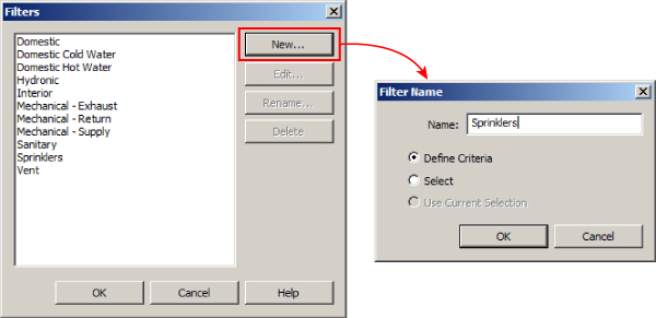
Figure 2.1 Creating view filters
When creating a new filter, notice that until you select items from the list of categories, you cannot proceed, nor can you select another filter. As with the Visibility/Graphic Overrides dialog box, you can filter the list of categories so that only the relevant categories are displayed, as shown in Figure 2.2.
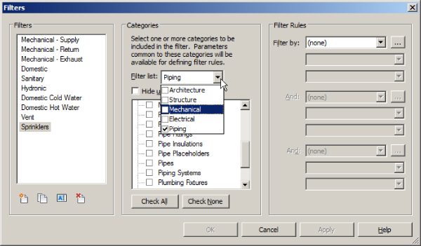
Figure 2.2 Filters dialog box
Select the categories you want to be part of the filter set, and you are ready to apply the filter rules. Let's say we are creating a Sprinklers filter set. We would choose Pipe Accessories and Fittings, Pipe Placeholders, and Pipes. Under Filter Rules, we could then filter by System Classification, which contains the case-sensitive words Fire Protection, as you can see in Figure 2.3.
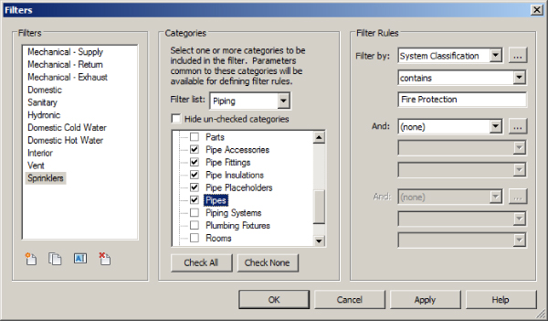
Figure 2.3 Sprinklers filter settings
In the previous paragraph, I mentioned System Classification, which for many filters is the default setting. Due to the large number of filters that you may well end up using in your project template, I advise you to change this so you filter by System Abbreviation instead. This helps to identify and separate your systems in a way that is clearer to your end users, and it is more flexible than the default System Classification setting.
Here's an example. The default Mechanical - Supply filter rule is set to Filter By “> System Classification” with the rule “contains” and the value “supply.” This may not be a problem for small projects, but for larger ones with multiple supply systems, it just won't work. This limitation is especially obvious for piping systems, where distinguishing between all the supply and return systems is critical. System Abbreviation has the necessary flexibility to allow for distinguishing among hundreds of systems. To create new system filters, the easiest method is to select an existing system filter and then click the Duplicate icon. Once the system filter is duplicated, make sure the proper category elements are selected and then rename the filter rule to the name by which you want to filter.
To apply these filters to your views, you can go to the View tab on the ribbon and then select Visibility/Graphic Overrides. Next, select the Filters tab (see Figure 2.4).
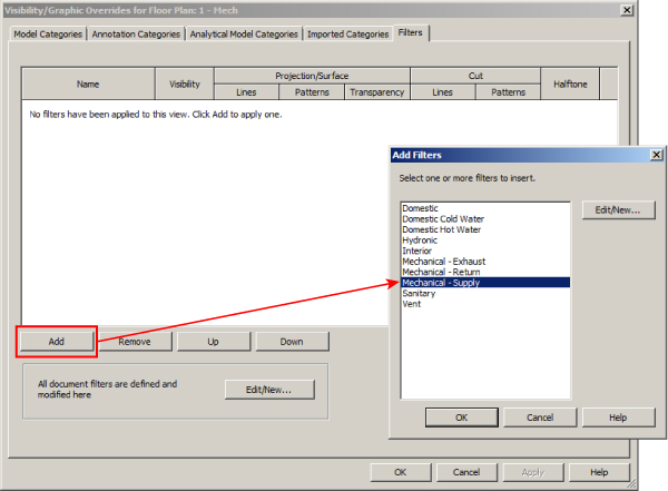
Figure 2.4 Applying view filters
On the Filters tab, click Add. This brings up the filters that you have created, so select the filters that apply to your project. Once the filters are loaded, you can turn the filters on and off and adjust line weights, colors, and patterns. It might be a good idea to test whether your filters are working properly by turning them off one at a time and ensuring that the appropriate elements are turned off in the view.
Mastering filter options will give you the ability to create your models with the standards that your office has developed over years of producing CAD drawings.
Prior to the introduction of duct and piping systems as system families in Autodesk® Revit® MEP 2012, filters were also used to control the color and the linetype of pipes and ducts. Some companies may still choose to do it this way, but the main benefit of using the duct and piping systems is that the color and linetype are set globally instead of per view. This benefit is most obvious when you start creating additional views such as sections and callouts and you need to keep adding the filters to get the colors of the systems. Since Revit MEP 2012, the proposed workflow is to control color and linetype with duct and piping systems, and use filters to control the visibilities of elements. Keep in mind, if you are using linked MEP models, you will have to use a view filter to change the colors and other overrides in the linked file. Or, using an option new to Revit 2016, you can override the graphics of the linked file and specify the linked view you want to see and its associated view filter(s).
Another type of filter is the selection filter. Selection filters allow you to create and save a filter set for selected items only instead of an entire object category. To do this, select your objects, and from the ribbon, choose Save Selection, as shown in Figure 2.5. Give the selection set an appropriate name.
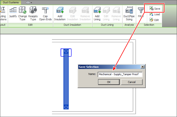
Figure 2.5 Selection set
Once created, access the Filters dialog box again and notice that the filters are shown slightly differently: there is now a section labeled Rule-based Filters and another labeled Selection Filters. With your new selection filter highlighted, you can see that the Categories and Filter Rules panels are deactivated because you are applying the rules to the selection only, as indicated in Figure 2.6.
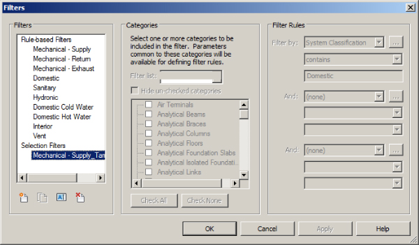
Figure 2.6 Selection set filters
Discipline Example: Filter for Wire Types
To create a filter for wires, do the following.
- First, click the Filters button located on the Graphics panel of the View tab.
- In the Filters dialog box, click the New button in the upper-left corner.
- Give the filter a name that clearly identifies its purpose or the types of elements to which it applies. You can use the Select option and select a wire in the view to create a filter for the selected items only.
- Use the Define Criteria option to create a filter for all of the instances of the desired type that you want to display.
- In the Categories section of the dialog box, select the Wires check box to apply the filter to wires.
- In the Filter Rules section of the dialog box, choose the Type Name parameter from the Filter By drop-down list.
- Set the condition to Equals in the second drop-down list, and choose the name of the wire type to which you want to apply the filter in the third drop-down list.
- This creates a filter that affects only wires with the type name chosen, as shown in Figure 2.7.
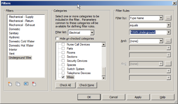
Figure 2.7 Filter settings for a wire-type filter
To apply the filter to your view:
- Access the Visibility/Graphic Overrides settings for the view and select the Filters tab.
- Click the Add button in the lower-left corner, and choose the filter you created for the wires from the Add Filters dialog box.
- Click the Override button in the Lines column for the filter. Set the Weight, Color, or Pattern overrides for the filter to display the wire as desired. Figure 2.8 shows floor boxes with underground wire in the same view as receptacles with wire as it is normally displayed.
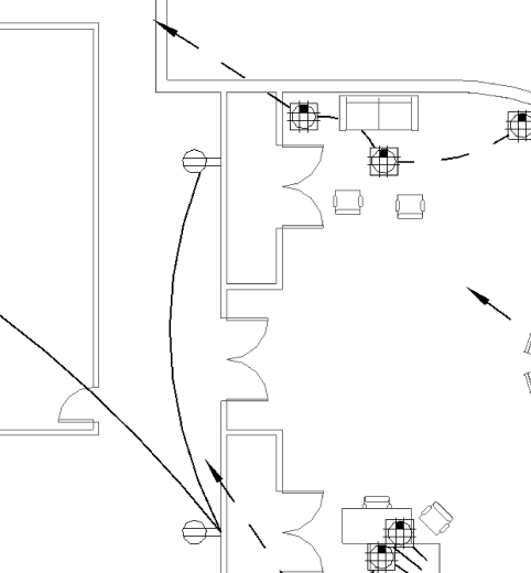
Figure 2.8 Using a filter to display different wire types in the same view
Visibility Settings Shortcut: View Templates
View templates are a great way to maintain the visual fidelity of many views for the same discipline in a few short steps, and it is best practice to have a default set of these predefined within your project template(s). View templates enable you to preset properties of view types that can be applied to any view in one simple step. These are not just visibility properties; you can also set many of the main properties of a view.
You can create a view template by clicking the View Templates button on the View tab of the ribbon and then selecting the Manage View Templates option. On the left side of the dialog box is a list of view templates that exist. You can sort the list by view type by using the drop-down list in the upper-left corner. The right side of the dialog box lists the commonly used view parameters that the view template can control or affect. Set the default values for these parameters to establish the scope of the view template.
There are also Edit buttons for the various tabs within the Visibility/Graphic Overrides dialog box. The Graphic Display Options have been separated into Model Display, Shadows, and Lighting settings. Any project parameters you create that apply to views will also be available within each view template.
The buttons in the lower-left corner of the dialog box are for duplicating, renaming, or deleting a view template. There is no button to create a new template; this option in this dialog is to duplicate an existing one. If there are no view templates existing in your file, you cannot access the View Templates dialog box from the ribbon. The way to create your very first view template in a project is either to click the Create Template From Current View button, or to right-click the view in the Project Browser and select Create View Template From View. You can also use Transfer Project Standards to acquire view templates (or any other settings) from another project. Either way, Revit will prompt you for a view template name and then open the View Templates dialog box.
A more common method for creating a view template is first to create a view and carefully configure how it looks. Once you are satisfied with how everything looks in the view, it is the perfect candidate for the Create View Template From View tool (right-click option). This is a preferable method because you can see what the view will look like as you make adjustments to the properties. Creating a view template this way in your project template requires you to load a model temporarily to be used as the visual reference. You can also use the View Templates button on the View tab and select the Create Template From Current View option, as shown in Figure 2.9.
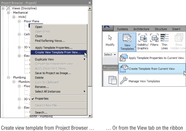
Figure 2.9 View Templates button
In the View Templates dialog box, there is a check box next to each property that you can use to determine whether the settings of the template for that property will be applied to the view. This enables you to apply only the desired portions of a view template if necessary. By applying a view template to a view, if the Visibility/Graphics check box is selected, you will no longer be able to control Visibility/Graphic Overrides from the Visibility/Graphic Overrides dialog box; instead, you will be controlling multiple view settings at once from Manage View Templates. This applies to all settings that are controlled by the view template, as seen in Figure 2.10.
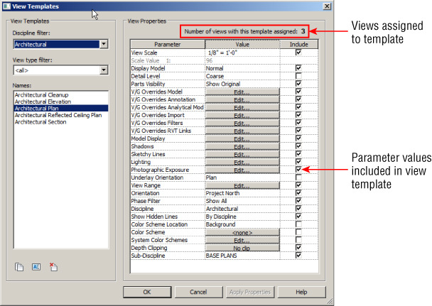
Figure 2.10 Manage View Templates
Not only can you manage these view templates, but you can also see just how many views are controlled by any one view template, also seen in Figure 2.10.
View templates can be made while creating your project template, but it is often easier when working on an actual project, so if you are in the early stages of implementing Revit, you can use the Transfer Project Standards tool to take view templates from a project file to your template. Revit gives us the ability to assign a view template to any given set of views, and those views update if the view template is changed. You can also apply any view template to any view, especially newly created ones, and quickly have the desired settings. When you work on a large project that has many levels or many dependent views, having view templates can save a significant amount of time.
The Bottom Line
- Set up view filters. The settings for views are crucial to being able to visualize the design and model being created and edited in a project. Establishing the default behavior for views and visibility of objects can increase not only the efficiency of working on a project but also the accuracy of design.
- Master It The properties of a view determine how objects and the model will appear in the view. Along with Visibility/Graphic Overrides, what other view property determines whether items are visible in that view?
- Establish filter standards. For consistency and ease of use, maintain a set of view filters and view templates as an aid to boost efficiency in your documentation.
- Master It What is the importance of using view filters?
- Control multiple views. With view templates, you have the ability to maintain a consistent appearance to your documentation.
- Master It True or false: A view template can control only one view at a time.