Chapter 7
Schedules
Schedules of a parametric model provide the most immediate return of information from the data inherent in the model. With the Autodesk® Revit® MEP 2016 platform, you can create schedules that are useful not only for construction documentation but also for data management, for object tracking, and even for making design decisions.
By building a model, you can look at it from many angles or viewpoints. Schedule views are simply another view of the model. Instead of looking at the physical elements that represent the design, a schedule allows you to view the data within the components in an organized and easy-to-manage format. Using schedules for data management is one way to increase efficiency, accuracy, and coordination within your Revit project. You can edit the properties of many objects quickly without having to locate the objects in the model.
Revit schedules can provide you with an accurate account of the objects that are being used in your project model. The ability to track and manage objects can help with cost estimation and material takeoff. With this information readily available, you have the power to make decisions that affect cost and constructability.
Harnessing the power of creating schedules in a Revit MEP 2016 project can help you reap the benefits that come with easy access to any model or project information.
In this chapter, you will learn to do the following:
- Use the tools in Revit MEP 2016 for defining schedules and their behavior
- Schedule building components
- Create schedules for design and analysis
- Schedule views and sheets for project management
Defining Schedules
Mastering the scheduling tools in Revit MEP 2016 will enable you to easily extract information from your projects. Schedules can be created and used on any of your Revit projects to establish consistency on construction documents and ease of data management for specified model objects.
Although there are different types of schedules, depending on their use and the items with which they are associated, the tools for creating them in Revit MEP 2016 are similar for whatever type of schedule you are creating. Because schedules are essentially a view of the model, the scheduling tools are located on the View tab of the ribbon, as shown in Figure 7.1.
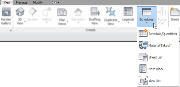
Figure 7.1 View tab
Figure 7.2 shows the types of schedules that can be created by clicking the Schedules button. Note the filter list that allows you to narrow down the number of categories available in the list displayed.
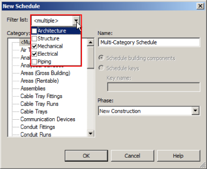
Figure 7.2 Schedule types
Clicking the View List or Sheet List option takes you directly to the View List or Sheet List Properties dialog box, where you can begin creating your schedule. Clicking the Schedule/Quantities or Material Takeoff option takes you first to a dialog box that allows you to select the Revit object category that you want to schedule. The Note Block option takes you to a dialog box where you can select the annotation family that you want to schedule.
In the New Schedule dialog box, you can define whether you are creating a schedule of building components or a schedule key. You can also set the project phase of the schedule view.
The project phase is an important property of schedules because only the objects in the model that belong to the same phase as a schedule appear in that schedule. The name that you give your schedule is what will appear in the main header of the schedule when it is placed on a drawing. If your drafting standards dictate that the text should be in all capital letters, that is how you need to type the name. From the Filter List pull-down, you can filter the object categories you can schedule. The pull-down is the same as the one in the Visibility/Graphic Overrides dialog box. This allows you to select items that are not MEP objects and may not even exist in your model. Figure 7.3 shows a sample of the New Schedule dialog box with settings to build a Spaces schedule.
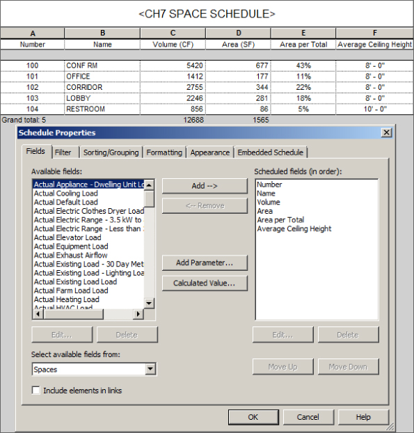
Figure 7.3 Sample schedule settings
Also note the angle brackets (< >) around the name of the schedule. This feature denotes a parameter value rather than user-entered text. You will learn of this and other features of scheduling later in the chapter.
Another choice is to create a Multi-Category schedule. This type of schedule is for objects that are in different categories but have common parameters. Figure 7.4 shows an example of a Multi-Category schedule. Notice that the OmniClass Number parameter is used in the schedule even though not all objects have that parameter.
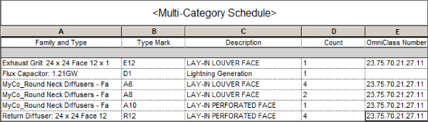
Figure 7.4 Sample Multi-Category schedule
Once you have chosen a category and established the initial settings from the new schedule dialog box, clicking OK opens the Schedule Properties dialog box. This dialog box has five tabs across the top that have settings for defining the behavior and appearance of your schedule. When you're scheduling Space or Room objects as in Figure 7.3, there is an additional tab for building an embedded schedule within the schedule you are creating. A typical use for an embedded schedule might be a Space schedule that also references lighting fixture details, so quantities of lighting fixtures per space or room can be created. An example of this is provided later in this chapter. It is good to move through the tabs sequentially, establishing the settings in each tab before moving to the next. The first two tabs let you determine what information will be scheduled, whereas the last three enable you to control how the data will be displayed and the graphical appearance of the schedule when placed on a drawing.
The Fields Tab
The Fields tab of the Schedule Properties dialog box contains many tools for choosing the information that will appear in a schedule. Figure 7.5 shows the Fields tab of a newly created Space schedule.
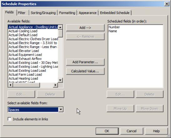
Figure 7.5 Fields tab of the Schedule Properties dialog box
The check box in the lower-left corner allows you to schedule items that are in any files that are linked into your project. The Available Fields list on the left side of the dialog box contains all the parameters that can be scheduled for the chosen category. The Edit and Delete buttons below the list become active only when you select a project or shared parameter that you have created. Only project parameters that are not shared parameters can be deleted.
You can use the drop-down list in the lower-left corner to change the list of available fields to parameters from another category. This is primarily for Space and Room schedules because the two objects are essentially the same thing. You cannot select fields from Mechanical Equipment if you are creating a Lighting Fixture schedule, for example.
To establish the columns in your schedule, you simply select the parameter from the Available Fields list and click the Add button at the top center of the dialog box. This places the chosen parameter in the space on the right side of the dialog box. Another way is to double-click the parameter you want to add. Each parameter added to the schedule will be a new column, and the order in which they appear in the list determines the order of the columns in the schedule, from left to right. Once you have added a parameter to the schedule, you can use the Move Up and Move Down buttons to set the order. These buttons become active only when you select a parameter from the Scheduled Fields list on the right.
The Remove button at the top center allows you to remove a parameter from the schedule. This is not the same thing as deleting a parameter. Using either of the Delete buttons removes the selected parameter from your project and any objects in your project. This can only be done with project or shared parameters, not the system parameters that are hard-coded into the program.
If you want to schedule information about the chosen category and a parameter does not exist that contains that information, you can click the Add Parameter button at the center of the dialog box. Clicking this button activates the Parameter Properties dialog box, where you can choose the type of parameter and its properties. The check box in the lower-left corner of the Parameter Properties dialog box (Add To All Elements In The Category) is selected by default, and it is grayed out to ensure that the parameter you create is added to all the objects in the category you are scheduling. Once you have created a parameter using this button, it is automatically added to the schedule.
Revit schedules have the ability to perform calculations on the data within the parameters that are included in a schedule. This information then appears as a unique column in the schedule. To create a calculated value column in your schedule, click the Calculated Value button at the center of the Fields tab in the Schedule Properties dialog box. Give the value a descriptive name so that when it is seen in the list or schedule, its purpose will be clear. You can create a formula by including parameters in a mathematical equation, or you can calculate a percentage.
The percentage calculation returns the percentage of a specific parameter as it relates to the project as a whole. Figure 7.6 shows the settings for percentage calculation of the volume of Space objects and the resulting column in the schedule.
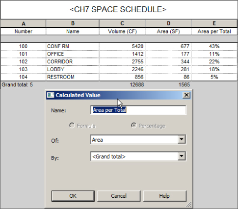
Figure 7.6 Percentage calculation in a schedule
When you're creating a calculated value based on a formula, it is important to use the proper Discipline and Type settings that coincide with the result of the equation. You will receive a warning stating that the units are inconsistent if the result does not match. Revit is case sensitive when it comes to typing in parameter names, so as you write your formula, it is crucial that you type the parameter name exactly. The small button next to the Formula field allows you to pick the parameter from a list and insert it into your formula to ensure proper spelling and capitalization. A good rule of thumb is to be consistent with all your parameter names.
Once you have created a calculated value, it automatically appears in the Scheduled Fields list. If you use the Remove button to remove a calculated value from the schedule, it is deleted from the project. You can use multiple operators and multiple parameters to create complex formulas if necessary. One example of a simple formula for Space objects is to divide the volume by the area to determine the average ceiling height, as shown in Figure 7.7. This formula works only because the Space objects have an upper limit set to the level above and the ceiling objects are set to Room Bounding, thus defining the volume of the spaces.
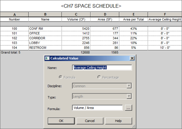
Figure 7.7 Space schedule with a calculated value for Average Ceiling Height
The Filter Tab
The next tab in the Schedule Properties dialog box is the Filter tab. The settings on this tab allow you to filter out unwanted items in your schedule. You can set certain criteria for parameter values that objects in the schedule category must meet in order to be included in the schedule. This is very useful when scheduling a category that has many unique types of items, such as the Mechanical Equipment category. For example, if you wanted to create a Pump schedule, you would have to schedule the Mechanical Equipment category. Without applying a filter to your schedule, all items categorized as Mechanical Equipment would show up in your schedule.
You can apply up to eight conditions that an object must meet to make it into the schedule. To set a condition for a parameter, that parameter must be included in your schedule. If you want to use a parameter for filtering but do not want it to show up in your schedule, you can use the options on the Formatting tab to hide the column of the unwanted parameter. There are some parameters (such as Cost, Family, and Type) to which you are not able to apply conditions.
Figure 7.8 shows a sample of a Mechanical Equipment schedule without any filter conditions applied to it.
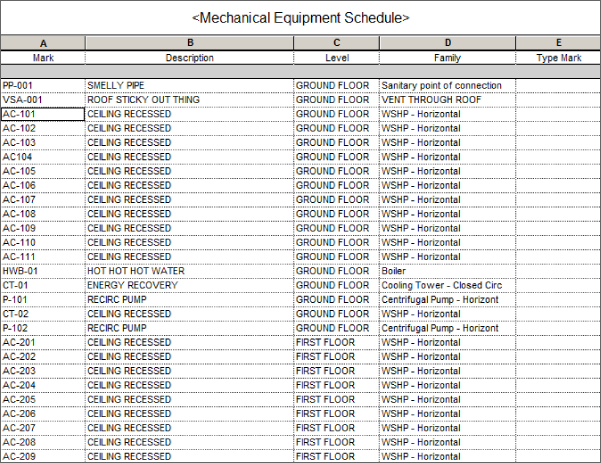
Figure 7.8 Sample Mechanical Equipment schedule
To turn this into a Pump schedule, you would apply the Filter settings shown in Figure 7.9. Notice the many options for filter rules that can be used to narrow down the qualifying objects. Using these conditions in combination with certain parameters gives you a very powerful tool for scheduling exactly the objects you want.
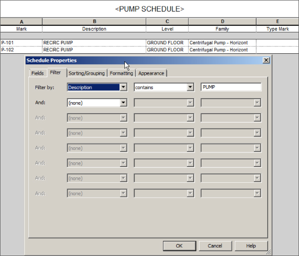
Figure 7.9 Filter settings for a Pump schedule
As items are brought into your model, they automatically appear in a schedule of their category as long as they meet the filter criteria. Remember that if you filter by a parameter, an object may not have a value assigned, so you should input data into the parameter when the object is brought into your project. This ensures that your schedule is showing all that it should. Additionally, you can use a working schedule, one that does not filter elements and is never placed on a sheet.
As mentioned earlier, another option for filtering a schedule is to set the schedule phase. The different options for the phase filter of a view can be applied to schedule views in the same way that they are applied to model views. So if you were to set the phase of a schedule view to New Construction and the phase filter to one that shows only New Construction, no items from any previous phase would appear in the schedule. You can select the phase from the New Schedule dialog box shown in Figure 7.2. There is no way to go back to that dialog box once you proceed, but you can change the phase of the schedule at a later time from the Properties palette.
The Sorting/Grouping Tab
In the Sorting/Grouping tab of the Schedule Properties dialog box, you can determine the order of the objects in a schedule and then group like items together. You can assign up to four group conditions and provide a header or footer for each group. Sorting can be done based on parameters that are used in the schedule. When you sort by a particular parameter, all the objects in the schedule that have the same value for that parameter are listed together.
Figure 7.10 shows a sample Lighting Fixture schedule that has been sorted by the Type Mark parameter. Notice that each instance of the different fixture types is listed in the schedule and that the Count column (QTY) on the far right of the schedule confirms this.
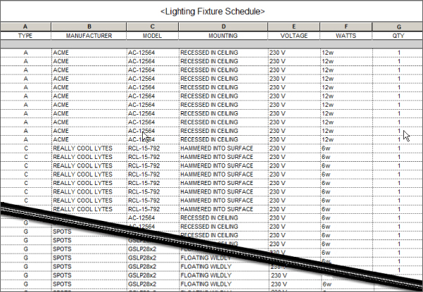
Figure 7.10 Sample Lighting Fixture schedule
A schedule lists each instance of the objects by default. To group items together that have the same parameter values, you need to deselect the box in the lower-left corner of the Sorting/Grouping tab of the Schedule Properties dialog box. Figure 7.11 shows settings for the same Lighting Fixture schedule, where the Itemize Every Instance box has been deselected. Notice that each type of lighting fixture is listed only once; that's because the schedule is set to sort by fixture type. The Count column now indicates the total number of each type of fixture. The Grand Totals check box has also been selected to give a total number of lighting fixtures at the bottom of the schedule. You can also create a custom grand total title.
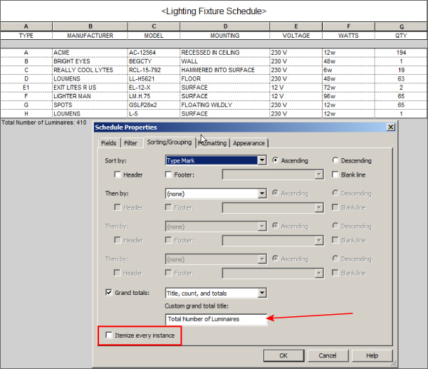
Figure 7.11 Lighting Fixture schedule sorted and grouped by type
You can use the Sorting/Grouping settings with combinations of parameters to organize your schedules so that you can read the data within them easily. Figure 7.12 shows the Lighting Fixture schedule again, with settings to sort by the Type Mark parameter and a footer to indicate the total number of fixtures. The Ascending or Descending radio button can be used to determine the order of items within a sorted group. Notice that the fixture types are listed in alphabetical order because the Ascending option is used.
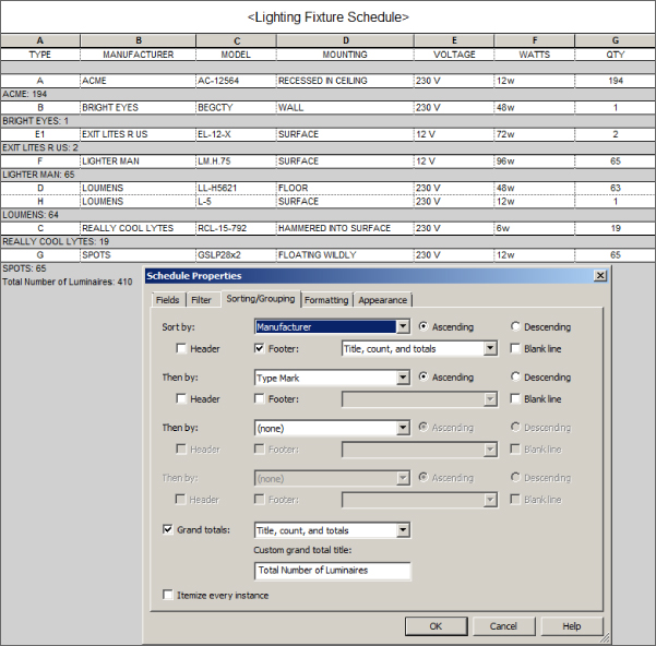
Figure 7.12 Lighting Fixture schedule with two sorting options
The Formatting Tab
The Formatting tab of the Schedule Properties dialog box has tools for setting how the data appears within a schedule. Each parameter used in the schedule is listed on the left side. When you select a parameter from the list, you can apply the settings available on the right side. You can also apply the settings to multiple parameters by holding down Ctrl or Shift.
The Heading setting establishes the name of the column in the schedule. The parameter name is used by default. Changing the column heading has no effect on the parameter itself, as shown in Figure 7.13, where the column headings have been changed to all caps. Even if the parameter name is what you want for your schedule column heading, you have to retype it if you want it in all capital letters. Figure 7.10, Figure 7.11, and Figure 7.12 are also good examples of this practice, where all the headings are in all caps (TYPE, MANUFACTURER, etc.).
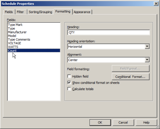
Figure 7.13 Column heading settings
The Formatting tab also has settings for the orientation of the column headings and the alignment of the data within a column. Headings can be either vertical or horizontal, and the data can be aligned to the left, right, or center of a column.
Two additional types of formatting are available, depending on the type of parameter selected. The Field Format button becomes active when you select a parameter that is a measurement. In the Format dialog box that appears when you click the Field Format button, you can change the units and rounding accuracy of the data. You can also choose whether to show the unit symbol in the cell of the schedule. Whatever settings have been established for the project are used by default. You can deselect the box at the top of the Format dialog box to overwrite the settings within the schedule. Figure 7.14 shows format settings for the Area parameter used in a Space schedule. Unit Symbol has been set to None because the schedule column heading indicates the units.
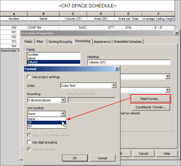
Figure 7.14 Field format settings
You can change the background color of a cell based on conditions that you apply by using the Conditional Format button. Clicking this button opens a dialog box where you can set a test condition for the value of a parameter and the background color of the schedule cell when the condition is met or not met. Additionally, you can display this conditional format on your output sheets. To do this, simply select the check box Show Conditional Format On Sheets. Figure 7.15 shows the Conditional Formatting dialog box for a calculated value in a schedule. The Background Color is set to turn red when the result of the calculation does not meet the test condition. The types of condition test options are shown in the Test drop-down list of the dialog box.
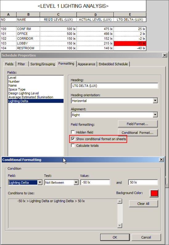
Figure 7.15 Conditional Formatting dialog box
On the Sorting/Grouping tab is an option to display the totals for groups of objects. If you want to show the totals for an individual column, you can select the Calculate Totals box when you select a parameter on the Formatting tab. These totals will not appear if the Grand Totals option is not selected on the Sorting/Grouping tab.
Sometimes you need to include a parameter in a schedule for sorting purposes or for calculations but you do not want to display the column in your schedule. If this is the case, you can use the Hidden Field check box on the Formatting tab to hide a selected column. This can be very useful because it allows you to hide information without having to remove the information from your schedule. It also allows you to create a schedule with more information that is useful for calculations or design decisions but is more than would normally be shown on a drawing. When the time comes to put the schedule on a drawing, you can hide the unwanted columns.
The Appearance Tab
The Appearance tab of the Schedule Properties dialog box contains the settings that define how the schedule looks when placed on a sheet. Grid lines and an outline can be chosen from any of the line styles defined in your project. If you do not choose an option for the outline, the line style chosen for the grid lines will be used. The option to include grid lines within the headers, footers, or spacers is also available.
The check box to provide a blank row between the headings and schedule data is selected by default. If this is not how you normally display your schedules, you have to deselect this box whenever you create one. The Appearance tab also has settings for the text within a schedule, as shown in Figure 7.16. The font and text height that you choose for header text will be applied to all headings, subheadings, and the title of the schedule unless you opt to override these in the schedule itself. To do that, select the title or heading, and from the ribbon, select Font in the Appearance panel.
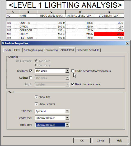
Figure 7.16 Appearance tab of the Schedule Properties dialog box
Editing a Schedule
Once you've created a schedule, you can edit it by using the same Schedule Properties dialog box. When you double-click a schedule in the Project Browser, the schedule is displayed in the drawing area. Using the Properties box, you can access the tabs for the instance Properties list of a schedule view, as shown in Figure 7.17. Each tab has its own Edit button, but clicking any of these buttons takes you to the Schedule Properties dialog box. Whichever button you click from the list takes you to the corresponding tab within the dialog box.
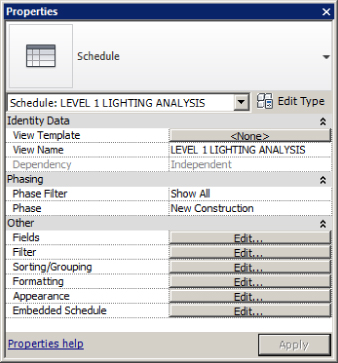
Figure 7.17 Schedule view properties
When you access the Schedule Properties dialog box, you can modify the schedule with any of the tools or settings that you would use to create a new schedule. One thing you cannot do is change what is being scheduled. For example, you cannot change a Lighting Fixture schedule to a Lighting Devices schedule because the Family category defines this.
Some of the formatting options that are defined can be modified in the schedule view, without having to access the Schedule Properties dialog box. In the schedule view, you can select anywhere within a column and use the Hide button on the ribbon to hide that column. There is also a Delete button on the ribbon to delete a row in the schedule. Of course, deleting a row in the schedule will also delete the object being scheduled, as noted in the sidebar “Delete with Caution.” The majority of formatting tools have now also been added to the updated tab for modifying schedules and quantities.
To ensure consistency between all your schedules, use view templates. View templates allow you to quickly apply your company standards to a schedule or a group of schedules. To create a new schedule view template, simply right-click a schedule and select Create View Template From View.
When you click in the cell of a column heading, you can change the text of the heading, eliminating the need to access the Formatting tab. You can change the title of the schedule with this method also, although this changes the name of your schedule in the Project Browser. Columns can be grouped together under a common heading by selecting the columns and clicking the Group button on the ribbon. Columns must be adjacent to each other to be grouped. The key to selecting columns for grouping is to hold down the left mouse button when you click the first column and then drag your cursor to highlight the columns to be included in the group. When you click the Group button, a new blank header appears above the columns, awaiting input. This is ideal for grouping similar data: locality details, measurements, and so forth (see Figure 7.18). Column groups can be removed by highlighting all the columns within a group and clicking the Ungroup button on the ribbon.
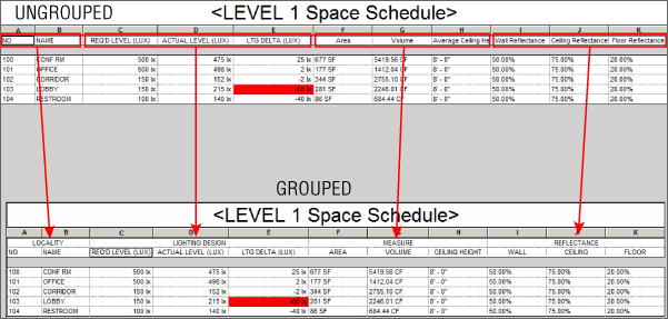
Figure 7.18 Schedule grouping
Another relatively recent improvement is the ability to add new rows in the header of your schedule. This lets you use the schedule like a spreadsheet, so you can make it look similar to the data sheets you have been using for many years in other packages. In Figure 7.19, a row was added by using the Insert option from the Rows panel on the Modify Schedule/Quantities tab of the ribbon.
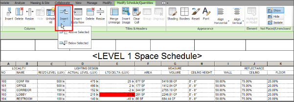
Figure 7.19 Schedule rows
Cells in this row can then be merged and parameters added to each merged cell as required. Figure 7.20 shows the schedule partially complete. Notice that fields can be added from the Parameters panel; text can be typed in; the size, font, and alignment of the values can be altered by using the Appearance panel; and an image—such as your company logo—can be added.
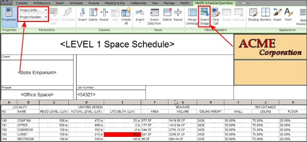
Figure 7.20 Schedule editing
This custom header can also have shading and borders applied either to individual cells or a selection, using the tools in the Appearance panel, as shown in Figure 7.21 and Figure 7.22. Click the appropriate button to change linetype, color, display, and so forth.
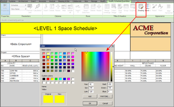
Figure 7.21 Schedule shading
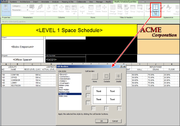
Figure 7.22 Schedule borders
One of the best features of using schedules in Revit is that you can edit parameter values of objects right in the schedule. If you are changing the value of a type parameter, you receive a warning letting you know that your change will be applied to all objects of that type when you finish editing the cell. Some cells turn into a drop-down list when you click them. This lets you select from previously input values for that parameter as long as those values are being used in the project. If you click a cell and you cannot edit it, that means that the parameter is a calculated value, it is a parameter of an object within a linked file, or the parameter does not exist in the object.
Because a schedule view is actually a view of the model, you can select a cell in a schedule and click the Highlight In Model button on the ribbon to see where the selected object exists in the model. This takes you to a view of the model, where the object can be seen. You can continue to click the Show button for different views. If you have grouped objects in your schedule and you are not itemizing every instance of the objects in it, then all the selected object types are shown. Used in conjunction with tiled views, this can aid in the selection and manipulation of objects.
Some schedules need multiple lines of input within one row, such as for comments or a description. You can do so by pressing Ctrl+Enter when entering information in a schedule cell or parameter value. Each time you press Ctrl+Enter, you create a hard return in the value, thus starting a new line of text. This process does take some practice, however; you cannot use the drop arrow to fill in subsequent cells because this method picks up only one line and in the schedule view, you see only the first line of input in the cell. To edit subsequent lines, use the keyboard arrow keys to navigate to the point in the cell, or use a spreadsheet and copy/paste the text from there. Do the same if you want to duplicate the data in another row. The multiple lines appear when the schedule is placed on a sheet.
Scheduling Component and System Family Data
Almost any object type that is placed into a Revit model can be scheduled. This seems like a very generic concept, but if you consider the possibilities that exist, it is easy to see why using a parametric model can be a great benefit to your design processes. Having readily accessible information about the components that make up your design makes coordination and decision making easier and more efficient.
It is important to know what kind of information about model objects can be scheduled, because the types of schedules that you can create for model objects depend on the data within those objects. Some data is inherent in the objects, based on how they are used in the model, such as elevation or location. Most of the data used in component object schedules comes from parameters that are added to the objects either as project parameters or directly in the component-family file as shared parameters. Family parameters cannot be scheduled.
Using the organizational and calculation tools within a Revit schedule can help you get the most from the data within the model components. The following sections cover some possibilities for scheduling building components.
Mechanical Equipment Schedules
The Mechanical Equipment model category covers a wide range of components—chillers, water heaters, pumps, rooftop units, fans, and more since they all fall under the Mechanical Equipment category. As you have seen, using filters makes it possible to create specific schedules for different types of Mechanical Equipment components. The key to success with these schedules is developing a method that makes the filtering easy to use and manage.
When considering the information that is needed in your schedules, you can look at the parameters that already exist in every component and determine whether they can be used in lieu of creating a custom parameter. The Description parameter is one example of a parameter that is in every object. With the ability to change the heading in a schedule, you can use this parameter for any type of descriptive information that is scheduled about your components. You do not need to create a parameter for each type of information to be scheduled. For example, if your Mechanical Equipment schedule for pumps has a column for the mounting type, you could use the Description parameter to convey this information.
Every item that is placed into a model is given a Mark value. The Mark parameter is another useful parameter for scheduling mechanical equipment.
The parameters Family And Type and Type do not appear under the Filter tab as a choice and therefore cannot be used for filtering objects.
The best reason for using the Mark parameter for Mechanical Equipment schedules is that it makes it easy to filter the schedule for specific items. Figure 7.23 shows a Mechanical Equipment schedule for pumps and the filter settings based on the Mark parameter. This setup allows for having unique Mark values for multiple instances of the same type of component.
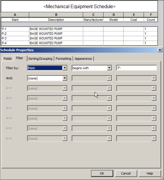
Figure 7.23 Pump schedule filtered by the Mark parameter
Another way to easily filter your Mechanical Equipment schedules is to create a project parameter called Schedule Type that is applied to the Mechanical Equipment category. You can then assign values for this parameter in order to create schedule filter rules. This may be the preferred method, because the Schedule Type parameter could be applied to all appropriate model categories and would give you a uniform method for filtering schedules.
If you have a schedule with a column for remarks or notes about an object, the Type Comments parameter can be a useful alternative to creating a custom parameter. The value of this parameter can refer to text notes associated with a schedule.
Lighting Fixture Schedules
The Type Mark parameter is useful for assigning a unique identifier to each fixture type within your project and eliminates the need for a custom parameter. If you use a standard set of fixtures for each design, you might consider naming each family type within your fixture families and using the type name to identify your fixtures in a schedule. The family type name shows up as Type in the Available Fields list, as shown in Figure 7.24.
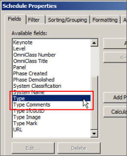
Figure 7.24 Family Type option in the Available Fields list
The URL parameter can be used for any component and is particularly useful for lighting fixtures. You can input a link to the cut sheet of a lighting fixture into its URL parameter for quick access to the additional information that a cut sheet provides. Figure 7.25 shows an example of a Lighting Fixture schedule with a URL column. When you click on the URL row, a small box at the right of the end of the URL cell shows up. The cut sheet file opens when you click that small box. Although this box is not initially visible, try clicking in the place where it should be. Notice how the URL responds, even though the box cannot be seen? Anywhere this type of box appears (URL, Material, Image, etc.), you can click this portion of the cell. That's a work-saving of 50 percent! Well, it's one fewer mouse click anyway, where there were two.
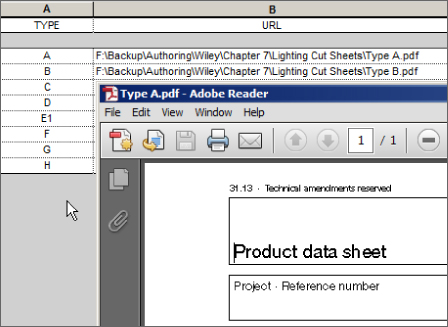
Figure 7.25 URL parameter used in a Lighting Fixture schedule
The paths you provide in URL parameters are not relative, so if you share or submit your Revit project file, the links are inactive unless you also share the cut sheets and you create new paths for the URL parameters.
System Family Schedules
Schedules are useful not only for component objects but for system families as well. Duct, Pipe, Cable Tray, and Conduit schedules can be created for use on construction documents or just for keeping track of quantities and materials.
Duct Schedules
A lot of information can be taken from a ductwork model. How you organize a Duct schedule depends on the type of information you are looking for and what you intend to do with it. Determining the amount of sheet metal for ductwork is one way to use the power of scheduling in Revit MEP 2016. Unfortunately, the Material Takeoff option of the Schedules tool on the View tab is restricted to component families. However, with some calculated fields and the right parameters, you can create a schedule that works as a material takeoff.
Figure 7.26 shows a sample Duct schedule with calculated values to determine the total area of material for both round and rectangular ducts. A duct material project parameter was created, and values were manually input for different duct types. The total area for each duct material is calculated at the bottom. This is just a small example of how you can get useful information from your model in schedule format. Keep in mind that because Revit is a parametric modeling tool, as ducts are removed, added, or changed, the schedule reflects those changes automatically.
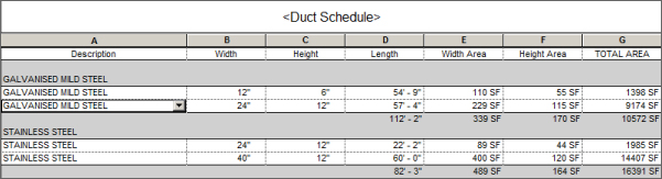
Figure 7.26 Sample Duct schedule
Another type of Duct schedule can help you keep track of what type of duct is used for different air systems. A schedule like this enables you to see whether any errors have occurred in the model based on design criteria. If all return-air ductwork is to be rectangular, for example, a schedule quickly reveals any duct that does not meet this requirement.
Pipe Schedules
Creating a custom Material Takeoff schedule for pipe is a little easier than for duct because pipe types can be assigned a material without creating a custom parameter. Figure 7.27 shows a sample Pipe schedule that is organized to show the total length of each pipe size per material.
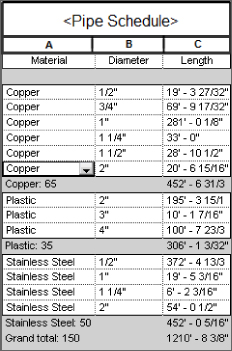
Figure 7.27 Sample Pipe schedule for a material takeoff
You can create Pipe schedules to input data quickly into the properties of pipes without having to locate each pipe in the model. One example where this may be useful is with pipe insulation. You can create a pipe insulation schedule like the one shown in Figure 7.28, which groups pipe insulations by their system types.
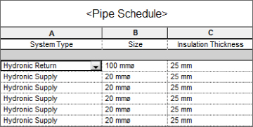
Figure 7.28 Sample Pipe Insulation schedule for parameter input
Insulation Thickness is an instance parameter of the Insulation Category. You can apply a value to several objects at once by grouping the insulation types and deselecting the Itemize Every Instance box on the Sorting/Grouping tab of the Schedule Properties dialog box. When you input a value for the Insulation Thickness parameter, it is applied to all pipes within that group. Just keep in mind that Insulation is considered a separate object, and pipes that don't have any insulation will not even appear on the Pipe Insulation schedule. For that reason, it is best to use two schedules: a Pipe schedule and a Pipe Insulation schedule. From the Pipe schedule, you can see and select the pipes that don't have insulation. While the pipes without insulation are still selected, you can apply Insulation from the plan view. Once all necessary pipes have insulation, you can manage them from the Pipe Insulation schedule.
Space Schedules
Spaces are typically scheduled to analyze their data to determine the performance of systems. However, creating a Space schedule can also help with model maintenance or quality control. A very simple Space schedule can be a useful tool for removing unwanted or misplaced spaces, reducing the risk of performing analysis of an incorrect model.
Spaces can be placed into a model manually or by using the Place Spaces Automatically tool on the Modify | Place Space contextual tab. The one drawback to the automated process is that Revit places a Space object in any enclosed area that is bounded by objects defined as Room Bounding and that is 0.25 square feet (0.023 square meters) or larger. This often results in Space objects being placed in pipe and duct chases or in column wraps and other small enclosures. In a large model, it could be time-consuming to search for all the unwanted Space objects, making the automation of space placement seem unreasonable. When these spaces are found, deleting them removes them from the model only. They still exist in the project and could be inadvertently used again or have unnecessary analysis performed on them. Additionally, undefined void spaces larger than the sliver space can affect energy analysis negatively because Revit and the cloud service interprets these as exterior surfaces instead of interior.
Consider creating a simple Space schedule that will quickly identify any unwanted spaces and allow you to, with a few clicks, either delete them all completely from the project or set them to not occupied or heated/cooled so energy analysis works properly. When you link in an architectural model, one thing you need to do is set the Room Bounding parameter so that it defines the boundaries of your spaces. Placing a space within the same boundaries as a Room object will associate that space with the architectural Room object. So, unless your architect has placed Room objects in areas such as chases or column wraps, you can easily see which of your spaces match up with the rooms.
Figure 7.29 shows the settings for a Space schedule that can be used to eliminate unwanted spaces. The schedule is sorted and grouped by room number and level so that all spaces without an associated level (Not Placed) or room will be listed together at the top of the schedule. Not Placed spaces could have been created as a fast-track design method or as a result of architectural changes. Either way, it is up to the user to decide whether they are required.
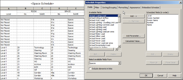
Figure 7.29 Settings for a Space schedule
The unwanted spaces can be highlighted in the schedule and then removed from the project by using the Delete button on the ribbon. You cannot use the Shift or Ctrl keys, but you can click and drag your cursor to select multiple rows within a Revit schedule.
The Schedule Properties dialog box for a Space schedule contains an additional tab for creating and managing an embedded schedule. This allows you to create an additional schedule that is set up within your Space schedule. On the Embedded Schedule tab, you can select the box to include an embedded schedule within your Space schedule and choose the model category you want to schedule. When you click the Embedded Schedule Properties button in the lower-left corner, a new Schedule Properties dialog box appears. You can then set up the embedded schedule in the same way you would set up a regular one. The Appearance tab is not available in an embedded schedule because the settings are controlled by the host schedule.
Figure 7.30 shows the Fields tab of a Lighting Fixture schedule that is embedded into a Space schedule. The fixtures in the embedded schedule are sorted and grouped by the Type Mark parameter, and grand totals are shown.
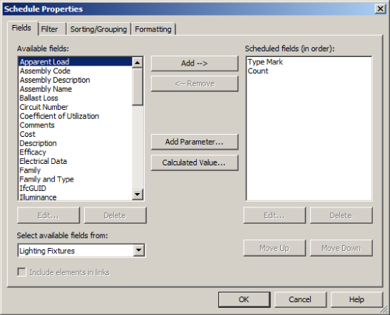
Figure 7.30 Embedded Lighting Fixture schedule settings
The information within the embedded schedule is included in the host Space schedule, as shown in Figure 7.31. By creating this type of schedule, you can see how many elements of a specific category are associated with each space.
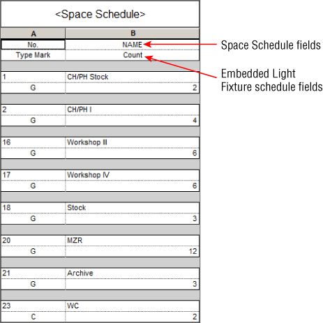
Figure 7.31 Space schedule with an embedded Light Fixture schedule
Model Component Schedules
Understanding the basic features of a component schedule will help you begin to develop your own methods for scheduling your Revit projects. Create a simple component schedule by doing the following:
- Open the
RMEP2016_Ch07_Dataset.rvtfile found at this book's web page,www.sybex.com/go/masteringrevitmep2016. - Click the Schedules button on the View tab and select Schedule/Quantities.
- Select the Air Terminals category. Ensure that the Schedule Building Components option is selected and that Phase is set to New Construction, and then click OK.
- On the Fields tab, select Type Mark from the Available Fields list and click the Add button. Repeat the process to add the System Type, Neck Size, CFM Range, Description, and Count parameters to the schedule.
- On the Sorting/Grouping tab, select Type Mark in the Sort By drop-down. Deselect the Itemize Every Instance box in the lower-left corner.
- On the Formatting tab, highlight all the parameters in the Fields list and set Alignment to Center.
- On the Appearance tab, select the Outline box and change the line style to Wide Lines. Click OK to exit the Schedule Properties dialog box. Your schedule should look something like Figure 7.32.
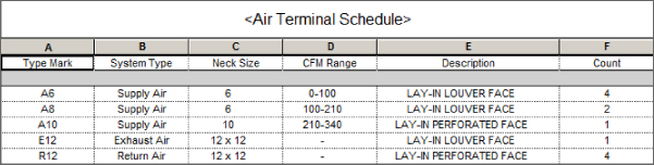
Figure 7.32 Air Terminal schedule
In the second half of this exercise, we take a look at creating a space schedule that also contains an embedded schedule of air terminals.
- Click the Schedules button on the View tab and select Schedule/Quantities.
- Select the Spaces category. Ensure that the Schedule Building Components option is selected and that Phase is set to New Construction, and then click OK.
- On the Fields tab, select Number from the Available Fields list and click the Add button. Repeat the process to add the Name parameter to the schedule.
- On the Filter tab, select Number in the Filter By drop-down and set Begins With as the rule. Type 1 in the field below the Filter By drop-down.
- On the Sorting/Grouping tab, select Number from the Sort By drop-down.
- On the Formatting tab, select the Number and Name parameters and set Alignment to Center.
- On the Embedded Schedule tab, select the Embedded Schedule box, select the Air Terminals category, and click the Embedded Schedule Properties button.
- Add the Type Mark, System Type, and Count parameters from the Available Fields list.
- On the Sorting/Grouping tab, select Type Mark in the Sort By drop-down. Select the Grand Totals box in the lower-left corner.
- On the Formatting tab, select the Count parameter and select the Calculate Totals box. Click OK to exit the Embedded Schedule Properties dialog box. Figure 7.33 shows the resulting schedule.
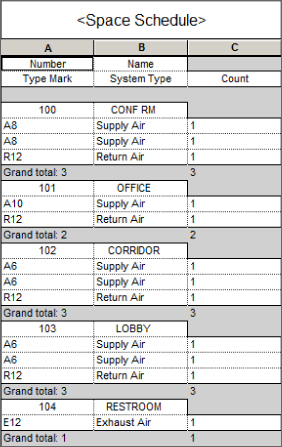
Figure 7.33 Embedded Air Terminal schedule
Using Schedules for Design and Analysis
Scheduling building components to provide information on construction documents or to keep track of model components and materials is not the only use for schedules in Revit. Using schedules to analyze the performance of MEP systems in relation to the building model can help you make design decisions. The ability to see and manipulate the information directly in Revit can improve the efficiency of your design processes.
Traditionally, engineers use several tools to complete building analysis. Some are used “because we always have and we trust the results” even though these processes can be time-consuming. It is important to verify your design data so the results can be trusted without just relying on the output. So, it is a great idea to run some small tests—side by side, your trusted software with the newfangled one. Revit MEP not only provides a great conceptual level of analysis, it does it faster than many of the programs around. What's more, the data from Revit can be exported to a GBXML format that can then be imported into other programs, allowing verification, confirmation, and more complex analysis without the time-consuming modeling or data input procedures required for those other packages.
When it comes to analysis, the focus is mainly on the Space objects in your model. Space objects hold a lot of information related to energy analysis, by direct input, input from third-party analysis, or as a result of the characteristics of components associated with the spaces. Understanding the type of information you can retrieve from spaces during the design process is the key to developing schedules that are most useful to your workflow.
Analysis can be as simple as checking to see whether the components you are using meet the engineering requirements or standards around which you are designing. This often requires that you manually set the requirement information property of your spaces. Selecting each space and accessing its properties to input this information is an inefficient practice.
Schedule Keys
A special type of schedule can be created to improve the process of adding information to your spaces. This is a schedule key, and it allows you to specify values for a parameter based on the value of a key parameter. One example is in lighting design, where a certain lighting level is required for specific types of rooms. A schedule key can be created to associate a specific lighting level value with each space key parameter value. The parameter associated with the key can be included in your Space schedule so that each space can be assigned a key and therefore a required lighting level. The required lighting level could be input manually into the parameter, but using a key ensures accuracy and consistency.
Click the Schedules button on the View tab and select Schedule/Quantities to create a schedule key. When you select the category you want to schedule, the option to create a schedule key becomes available on the right side of the dialog box. You can then choose a name for the key parameter in the Key Name field. A style-based name will automatically be placed in the Key Name field, but you can change it to whatever you want. After you create the schedule, a parameter with this name is added to all the objects in the category for which you are creating a schedule key. Figure 7.34 shows an example of the settings for a Space schedule key. Notice that the schedule has been named to identify it as a schedule key and not a component schedule.
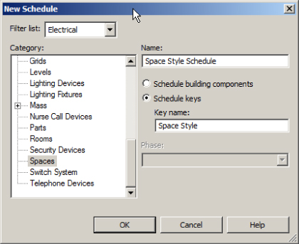
Figure 7.34 Space schedule key setup
The Key Name parameter is automatically included in the Scheduled Fields area on the Fields tab of the Schedule Properties dialog box. Here, you can select parameters to which values are assigned based on the key value. In the case of a Space schedule key for lighting levels, the Required Lighting Level parameter is chosen, as shown in Figure 7.35.
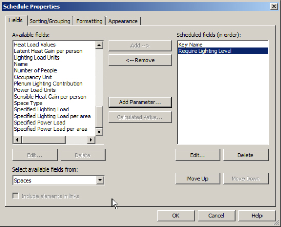
Figure 7.35 Space schedule key Fields tab
The schedule key is sorted by the Key Name parameter by default. Unless you will be placing the schedule on a drawing, there is no need for any other settings within the Schedule Properties dialog box. The schedule key starts out blank. Click the New button on the Rows panel of the ribbon to add a row to the schedule. You can then edit the name of the key and assign a value to the associated parameter. Repeat the process to create additional rows and build your schedule key. Figure 7.36 shows an example of a Space schedule key for lighting levels.
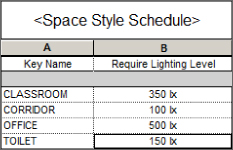
Figure 7.36 Sample schedule key
Now that you have created the schedule key, each space has a Space Style parameter that can be assigned a value from the schedule key for the Required Lighting Level parameter. A schedule can be used to assign these values without having to access the properties of each space. When you are editing a key parameter value in a schedule, a drop-down list appears with all the key values, as shown in Figure 7.37.
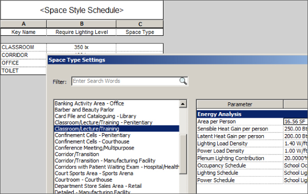
Figure 7.37 Editing a schedule key parameter
A key parameter can be included in a schedule that is set up for analysis to increase the functionality of the schedule. Additional parameters were added to the schedule shown in Figure 7.37 to determine whether the lighting levels in each space meet the design requirements. A calculated value was added to show the difference between the required level and what is actually occurring in the space. This type of schedule allows you to quickly see the performance of the design components used, and you can adjust parameter values of the spaces to investigate options. Notice in Figure 7.38 that spaces, which have been assigned a Space Style value, have the corresponding Required Lighting Level parameter value from the key.
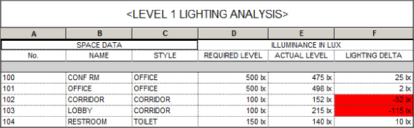
Figure 7.38 Space lighting level analysis schedule
This same type of schedule can be created for airflow in spaces. The design airflow value can be checked against the actual airflow and the value calculated by a third-party analysis or directly from the Revit MEP 2016 Heating and Cooling Analysis tool.
The ability to see the performance-based data is essential to checking the quality of your design and for making appropriate changes to the design when necessary. Figure 7.39 shows an example of a duct airflow schedule that displays the properties related to the performance of the system rather than information about the physical properties of the ductwork.
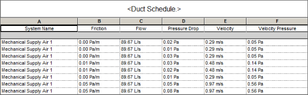
Figure 7.39 Duct Airflow schedule
Panel Schedules
Custom Panel schedules are not created by using the scheduling tools but instead are generated by a predefined format residing in a panel-schedule template. There are tools to create a panel schedule template with settings for both the appearance of the schedule and the data that is reported.
Once you establish panel schedule templates within your project template, they are available for use on any project. If you want to create a custom Panel schedule, the first step is to create its template. You can find the Panel Schedule Templates tool on the Manage tab.
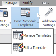
The Manage Templates option gives you access to your panel schedule templates for editing or duplication. Clicking this option activates the Manage Panel Schedule Templates dialog box. The first tab on the dialog box lists any templates in your file. The three types of panel templates that you can create are Branch Panel, Data Panel, and Switchboard, as shown in Figure 7.40.
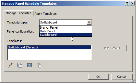
Figure 7.40 Manage Panel templates
Once you have created a panel schedule template, the Make Default button enables you to establish a selected template as the default. Buttons at the bottom of the dialog box can be used to edit, duplicate, rename, or delete a template.
The second tab of the dialog box allows you to apply a panel schedule template to any panel in your project. When you make changes to your panel schedule templates, these can be assigned to your panel schedules. You can also update the schedules for panels that are using an older version by selecting the panels from the list and clicking the Update Schedules button as indicated in Figure 7.41.
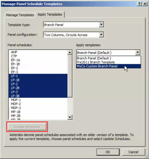
Figure 7.41 Apply Panel templates
To build a custom template, start by clicking the default template in the list on the Manage Templates tab of the dialog box. Use the Duplicate button at the bottom of the dialog box to copy the default template. Select the newly created template in the list, and use the Edit button to begin customizing your Panel schedule.
All the tools for editing and formatting a panel schedule template are located on the Modify | Panel Schedule Template contextual tab that appears on the ribbon when you click to edit a template. Every panel schedule template has a header area, a circuit table, a load summary area, and a footer. That does not mean that you have to use all four of these areas. You can access the settings for the overall appearance and behavior of a panel schedule template by clicking the Set Template Options button on the contextual tab.
There are three main areas for the overall settings. Figure 7.42 shows the General Settings options. The Total Width setting determines the size of the schedule when placed on a sheet. The height is determined by the row height settings within the schedule. Column widths are defined directly in the schedule template view. The number of slots shown is determined by the panel family used or defined here in the template options. You can deselect the boxes to remove the header, footer, or loads summary, but the circuit table cannot be removed.
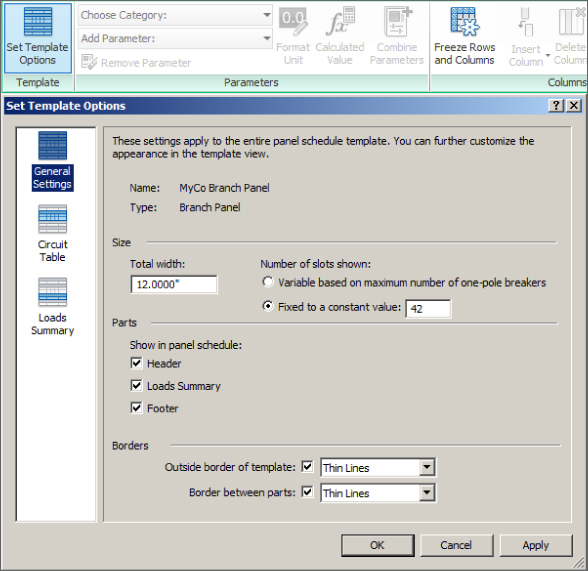
Figure 7.42 General Settings area for a panel schedule template
The Circuit Table options allow you to define the format for the columns that display circuit loads. Single-phase and three-phase panels can be created, with the three-phase loads column appearing in the center of your schedule no matter what you do to format the other columns. The values in these columns cannot be edited, and you cannot replace them with another parameter. In Revit MEP 2016 you have the ability to show the phase values as either Load or Current.
The Loads Summary options let you set which load classifications will be listed when the loads summary is included in your schedule. All load classifications that exist in your project are shown on the left, and the ones that appear in the schedule are listed on the right. If you choose the option for displaying only those loads that are connected to the panel, all the classifications move to the Scheduled Loads list. When you create a Panel schedule, only the classifications that are connected appear; however, the loads summary has blank rows for the unused classifications, as shown in Figure 7.43.
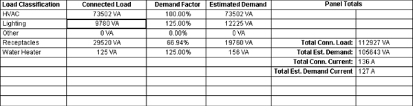
Figure 7.43 Loads summary
The tools on the Modify | Panel Schedule Template contextual tab of the ribbon are the same kind of tools that you would find in a spreadsheet program. You can merge cells, add or delete columns and rows, set the borders and shading of cells, and set the alignment of column data. You can also adjust the font for a cell or group of cells. Many of these tools are also available on a menu that appears when you right-click a cell in the schedule view. You can adjust row and column heights and widths by clicking and dragging the borderlines in the schedule view.
The Parameters panel of this tab has a drop-down for selecting a category and a drop-down for selecting parameters within a chosen category to be placed in a column. You can place unique parameters in individual cells in any area of the schedule except for the circuit table. When you click a cell in the circuit table and select a parameter, that parameter populates all the cells in that column and the corresponding column on the other side of the table. When you click a cell in the Circuit Table area, the only category available in the drop-down is Electrical Circuits. In other areas of the schedule, you can choose parameters from the Electrical Equipment and Project Information categories.
You can set the units to be used in the circuit table with the Format Unit button on the Parameters panel. There is also a button for creating a calculated value in a cell. This tool works the same way as in a building component schedule. The Combine Parameters button allows you to put multiple parameters in a single cell. It is similar to the tool for building a label in an annotation or tag family. You choose the parameters for a cell, the options for a prefix or suffix, and how the parameters will be separated if necessary.
Using Schedules for Project Management
You can apply the scheduling capabilities of Revit to other areas of your project to facilitate project management and organize construction documents. You can even use schedules as a way to coordinate plan notes and ensure coordination between notes and their callouts.
Sheet List
Another type of schedule available on the Schedules button is a Sheet List schedule. A Sheet List schedule is built with the same tools as a model component schedule, but all the parameters are related to sheets. Creating a Sheet List schedule is useful for managing your project documentation because the schedule allows you to track what sheets have been created, revised, and checked. You can create custom parameters that apply to sheets for management by other means.
If you are required to submit a list of all the drawings in a submittal package, you can use a Sheet List schedule. Using a Sheet List schedule ensures that all the sheets created in your project are listed. Some submittals do not require all sheets to be submitted, so a custom parameter that allows you to control what sheets are included in a submittal is a good way to manage your sheet list.
As with most schedules that appear on construction documents, it is a good practice to have two Sheet List schedules in your project: one that has all the parameters that you need for tracking and making changes and another that is actually included in your construction documents. This keeps you from having to hide and unhide columns when working in the schedule view. Figure 7.44 shows a Sheet List schedule with a parameter for whether a sheet is submitted and, on the bottom, the corresponding Sheet List schedule that appears in the construction documents. The schedule on the bottom is filtered by the Submitted parameter so that only sheets that are selected appear in the list.

Figure 7.44 Sheet List schedules
Even though you may have established how sheet views are organized in the Project Browser, it may not meet your requirements for listing the sheets included in a project submittal. You can use a custom parameter (Publish Order) to sort your Sheet List schedule in the order you require. You can use a numbering system in combination with the items being listed alphabetically to arrange the sheets in your schedule, as shown in Figure 7.45.
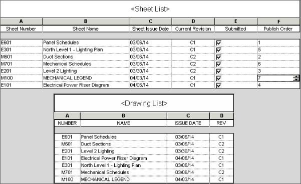
Figure 7.45 Sorting the Sheet List schedule
Notice that different decade groups are used for each discipline so that sheets can be organized within a discipline. This allows the electrical site plan to be listed before the plan sheets, for example, without requiring a unique number to be provided for each sheet.
View List
A View List schedule is another type of schedule that can be created from the Schedules button on the View tab. Similar to a Sheet List schedule, a View List schedule can help you keep track of the views that exist in your project.
When printing a set of construction documents, you want to be sure that all your views that should be on a sheet have been placed onto the appropriate sheet. Not only does this save you the time it would take to visually inspect each sheet, it can also save paper and wear and tear on your printer.
A View List schedule is constructed with the same tools as a Sheet List schedule, except only parameters that apply to views can be used in the schedule. Unfortunately, not all view parameters can be scheduled, but there are many that are useful for project management. When working in a project that includes phases, a View List schedule can be a useful tool for ensuring that views are set to the proper phase and have the proper phase filter applied.
To create a View List schedule that shows only views that are placed on sheets, you can use a filter. If you use the Sheet Number parameter as a filter with the Does Not Contain rule and leave the value blank, the expected result would be a schedule that shows only those views that are placed on a sheet.
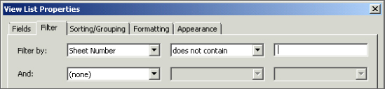
Normally, you would apply a filter to remove all the scheduled items that do not meet your filter requirements. However, using these settings actually removes all views that meet the requirements of the filter, causing your schedule to list all the views that have no value for the parameter.
Note Block
A Note Block schedule is based on an annotation family that is used in your project. Note Block schedules are useful for managing plan notes on your construction documents as an alternative to keynoting. As note annotations are placed in a view, they can be given a description, and then a Note Block schedule can be created to list the descriptions of each instance of the annotation. Figure 7.46 shows the properties of a note annotation family used for plan notes.
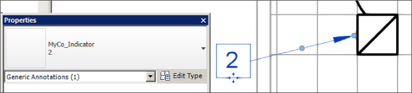
Figure 7.46 Note annotation properties
A Usage parameter has been created to determine to which sheet the note belongs. The Description parameter holds the contents of the note. Once a note annotation is placed in a view, it can be copied for each instance to create the next note in the list.
A Note Block schedule is created by choosing the Note Block option from the Schedules button on the View tab. The annotation family that is used for plan notes is selected to be scheduled. The title of the Note Block schedule should be a description of where the notes are located to make it easy to locate the Note Block schedule in the Project Browser. The Note Number, Description, and Usage parameters are added to the schedule. The schedule is then filtered by the Usage parameter so that only note annotations that appear on a specific sheet appear in the schedule, and the Usage parameter is hidden. The schedule is sorted by the Note Number parameter.
It is important to establish the Usage parameter value for the first note annotation placed into a view and then to copy that view whenever a new note is required. Copying the note annotation ensures that the Usage parameter value is the same for each note in the plan view. The Note Block view and its associated plan view can be tiled so that as you add note annotations to the plan view, you can see them appear in the schedule. The Properties palette gives you instant access to the Description parameter of the note annotation so changes can be made easily.
One benefit of using a Note Block schedule over static text for plan notes is that if you need to change what a note says, you can deselect the Itemize Every Instance option in the schedule to see each unique note; then, when you change the description of the note, it changes for all instances.
Another benefit is that if you need to delete a note, you can delete it from the Note Block schedule and all instances are removed from the associated plan view. This ensures that you do not have a note annotation in the plan view that references a note that does not exist in the plan notes. It also eliminates the need for having a note in the notes list with a value of Not Used because the notes can easily be renumbered in the Note Block schedule when a note is removed. Renumbering the notes in the schedule automatically updates the annotations in the plan view.
When you place the Note Block schedule onto a sheet with its associated plan view, you will want to adjust the Appearance settings so that the schedule title and headings are not shown, giving the schedule the appearance of a list rather than a schedule, as shown in Figure 7.47.
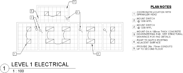
Figure 7.47 Note Block plan notes on a sheet
The symbolic representation for each note is provided by attaching a suitable image to the family, in the Type Image field, prior to loading the family into the project.
It can be easy to get carried away when importing images. It is a good idea to review each one to ensure project file performance isn't unduly affected by large files.
The Bottom Line
- Use the tools in Revit MEP 2016 for defining schedules and their behavior. The capabilities of schedules in Revit MEP 2016 can increase your project coordination and the efficiency of your workflow. The ability to track items within a model can help you better understand the makeup of your design.
- Master It The information in schedules comes from information stored within the objects of a Revit model. Explain why editing the data of an object in a schedule changes the properties of the object.
- Schedule building components. Scheduling building components is the primary use of the scheduling tools in Revit. Schedules are used on construction documents to provide additional information about components so that drawings do not become too cluttered.
- Master It Understanding what information can be used in a schedule is important to setting up a specific component schedule within your Revit project. What types of parameters can be included in a schedule? What types cannot?
- Create schedules for design and analysis. Scheduling can go beyond counting objects and tracking their information. You can also create schedules that assist in making design decisions by providing organized analytical information.
- Master It The information stored in Space objects often comes from their relationship with other objects. Some of the data for analysis needs to be input manually. Explain how using a schedule key can assist in adding data to a Space object.
- Schedule views and sheets for project management. You can schedule not just the components that make up a model but also the views and sheets within your project. Specialized schedules for views and sheets are useful for project management.
- Master It A Note Block schedule enables you to list information about annotation families within your project. What are some of the benefits of using a Note Block schedule instead of static text for plan notes?