
Chapter 12
Lighting
It may be difficult at first to see a good reason for making the effort to include lighting systems in a 3D building model. After all, lighting can be represented by drafting symbols, can't it? Although that is true, a BIM project is much more than just creating a 3D model. The data from an intelligent lighting model can be used for analysis and can aid in design decisions.
Including light fixtures and their associated devices in an Autodesk® Revit® model will allow you to coordinate your complete electrical design by providing electrical load information. They can also be used to develop presentation imagery by generating realistic light in renderings.
Creating a lighting model with Revit MEP enables you to develop your design while generating the necessary construction documents to convey the design intent.
In this chapter, you will learn to do the following:
- Prepare your project for lighting design
- Use Revit MEP for lighting analysis
- Compare and evaluate hosting options for lighting fixtures and devices
- Develop site lighting plans
Efficient Lighting Design
Let's face it; ceiling plans are one of the biggest coordination pain points for a design team. Nearly every MEP discipline has some type of element that resides in the ceiling. Using intelligent lighting families will help you, the electrical designer, stake your claim to that precious real estate. Using 3D geometry to represent light fixtures means that you can detect interference with other model elements. This does not mean that your lighting fixture families will have to be modeled to show every trim ring, reflector, tombstone, or lens. The basic geometry is usually enough to satisfy the requirements for model coordination.
The intelligence put into your families is what will benefit you the most from an electrical standpoint. Photometric data, circuit, panel, manufacturer, model, voltage, and number of lamps are just a few examples of the types of properties that can reside in your fixture families. You'll find an in-depth look at creating lighting fixture families in Chapter 20, “Creating Light Fixtures.”
Spaces and Lighting
For the spaces in your model to report the correct lighting level, they must be modeled accurately. If the height of the space is short of the ceiling, the lighting fixtures will not be recognized as being in the space and thus no lighting data will be seen or be detectable by Revit for that space. The room calculation point feature available in lighting fixture families allows you to associate a fixture with a space even though the fixture is not within the bounds of the space. See Chapter 20 for more information on this feature.
A ceiling can be defined as a room-bounding element, which means that it can define the upper boundary of a space. If you model your spaces so that their upper limit is higher than the ceiling heights, you can be sure that you are getting accurate volume information for the spaces. When you are placing spaces into the model, set the upper limit to the level above the current level on which you are working to ensure proper volumes. If you have a space that spans multiple ceiling heights (or floors), make sure you set the upper limit appropriately, as shown in Figure 12.1.
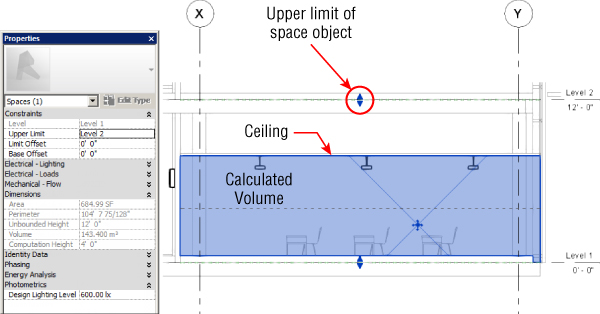
Figure 12.1 Space volume and ceiling relationship
Space volume is important to the proper calculation of average estimated illumination within a room. The ability to calculate the volume of a space can be turned on or off to help with file performance. If you intend to use Revit MEP to analyze your lighting design, you need to ensure that this setting is turned on. Do this by clicking the Room & Area panel drop-down on the Architecture tab, shown in Figure 12.2.

Figure 12.2 Room & Area panel
Select the Area And Volume Computations tool to access the settings for space volume computations. Choose the setting shown in Figure 12.3 when using Revit MEP for lighting analysis.
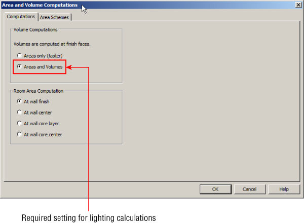
Figure 12.3 Areas And Volumes setting
You can practice placing and manipulating spaces by completing the following exercise:
- From
www.sybex.com/go/masteringrevitmep2016download the following files:RMEP2016_Ch12_Dataset.rvtRMEP2016_Sample_Architecture.rvt
- Open
RMEP2016_Ch12_Dataset.rvt. The sample architecture file is linked using the methods described in Chapter 4, “Project Collaboration,” which also describes what to do if the link file does not display. - From the Electrical Discipline of the Project Browser, open the floor plan LIGHTING First Floor.
- Check that the property of the linked file is set to Room Bounding by selecting the link, clicking the Edit Type button in the Properties palette, and selecting the Room Bounding box.
- Click the Space tool on the Analyze tab.
- On the Options Bar, set Upper Limit to Second Floor and Offset to 0′-0″ (0 mm), and place a space in the large curved room at the right side of the building.
- Create a Building Section view looking north through the large room.
- Open the section view, and select the Space object. (You may have to hover your mouse pointer on the room edges.) Notice that the upper limit is below the Ceiling object in the room.
- Check the instance properties of the space, and verify that the volume is computed under the Dimensions group. If not, go back and set your model to compute volume by adjusting the Area And Volume Computations settings on the Room & Area panel of the Architecture tab, as previously indicated in Figure 12.3.
- Once again, with the Properties palette showing the properties of the space, change the Limit Offset parameter value to 4′-0″ (1200 mm) and examine the Volume parameter value of the space. You may need to click the Apply button on the Properties palette for the change to take place.
- Change the Limit Offset parameter value to 6′-0″ (1800 mm), and note that the Volume parameter value stays the same. This confirms that the ceiling is acting as a room boundary.
- Open the LIGHTING First Floor plan view, and click the Space button on the Analyze tab to place another space in the room located in the upper-right corner of the building. Before placing the space, on the Options Bar, set the upper limit of the space to Level 2, and set the Offset to 0′-0″ (0 mm). Then click in the room to create the space.
- Create a section view of this room, and select the Space object. Notice that the space extends beyond the ceiling. This confirms that the ceiling is not set to be room bounding.
- In the section view, select the Space object, and use the grip arrow to stretch the top of the space beyond the Second Floor. Notice that the space does not come past the Second Floor Slab, indicating that the floor is correctly designated as room bounding.
- Continue placing spaces in the model, and examine their properties based on the settings you choose on the Options Bar for placement.
The Reflected Ceiling Plan
The first step in creating a well-coordinated lighting plan is to ensure that your reflected ceiling plan is properly set up to display the model in a way that allows you to see all the items necessary to coordinate as you design. Adjust the view range settings of your view so that all ceilings are clearly visible, and turn on any worksets or component categories from other disciplines that may contain items in the ceiling. You can set the categories from other disciplines to halftone to see your lighting layout more clearly. If you are linking in files from MEP consultants, use the visibility control options for linked files to achieve the desired result.
If you intend to display the ceiling grids on your lighting construction documents, you have to make visibility adjustments to ensure that the building model is displayed correctly. Remember that with a reflected ceiling plan, you are looking up at the model, so certain elements, such as plumbing fixtures or windows, may not appear as desired until you adjust the view range and the Visibility/Graphic Overrides. Stairs also display differently in reflected ceiling views than they do in normal plan views. Also, consider that the order of objects is different than in a plan view. A fixture shown below an object in a plan view appears to be above the object in a reflected ceiling plan view. This may have an adverse effect on your construction documents.
Another method for displaying ceiling grids on the construction documents of your project is to create a reflected ceiling plan view that shows only the ceiling objects. This view can be placed on a sheet in the same location as the lighting floor plan view. When placed onto a sheet, the view can be snapped to the same location as the floor plan view so you can be sure of the alignment. This allows you to display the model correctly as a plan view and still be able to see the ceiling grids or surfaces. For best results, you should place the ceiling plan view on the sheet first and then the lighting plan view on top of it.
There is often debate between architects and electrical designers as to whose model should contain the ceilings. Ceilings are not always required in early project submittals, so the architect may not get around to modeling them when the electrical designer needs them. This may prompt the electrical designer to create ceilings in their model in order to begin the lighting design, which can cause coordination issues after the architect begins designing the ceilings in their model. Having duplicate information in multiple models can be a recipe for error. The electrical designer would have to keep the ceilings in the electrical model coordinated with the architect's ceilings and would have to ensure that all model views were displaying the proper ceilings. This extra effort defeats the purpose of using a BIM solution such as Revit MEP and hampers the effort to achieve a coordinated project delivery because it adds another level of manual coordination that creates more opportunities for error.
You may use the option of creating reference planes in your model to host your lighting fixtures temporarily. When the ceilings are placed in the architectural model, you could then re-host your fixtures to them. Another option is to use nonhosted families in your project. Because you cannot replace a nonhosted family with a hosted one, you have to make the decision to use hosted or nonhosted.
Lighting fixtures that are modeled in the architectural model are another thing to consider. Many architects like to create lighting layouts for their design to get a feel for how the rooms will look with lighting fixtures in the ceiling or to create renderings. If the architect uses 3D families to represent the lighting fixtures, this can cause problems for the electrical designer when it comes to using the linked model for hosting. Lighting fixtures in the architectural model will most likely cut a hole in the ceiling where they are placed. An electrical designer who attempts to put a light fixture in the same location as the fixture in the linked file may not be able to do so because there won't actually be a ceiling there. There is also the chance that a face of the fixture in the link hosts the fixture in the MEP file. So if the architect deletes the fixture in their file, the fixture in the MEP file will not have a host and will not respond to changes.
Early in the project, the architect and electrical designer should agree on who will model the ceilings and in which model they will reside. They should also coordinate which types of families will be used if the architect intends to place lighting fixtures in the architectural model. If they need to be modeled in one file initially, they can be copied and pasted into another file if necessary. Another option is to use the Copy/Monitor tool to copy the lighting fixtures from the architectural model. The ultimate goal is to have one ceiling design that all disciplines can use for layout and coordination.
Lighting Worksets
When you're working in a model file with other MEP disciplines, it is best to create a lighting workset to distinguish model elements that would belong to that design system. It may even be necessary to create multiple worksets for lighting systems. Doing so will allow you to divide your lighting design into separate systems (such as interior and exterior) or by floor levels.
This can aid you in controlling the visibility of groups of model elements and can also help multiple users work on different sections of the lighting model at the same time without interfering with each other's designs.
Lighting Analysis
Because you are placing light fixtures for the purpose of a layout that is coordinated with other disciplines, you can also get design information that will help you make decisions on the types of lights to use. You can use the power of the scheduling capabilities of Revit MEP to create a schedule of the spaces in your model that shows the lighting fixtures used and the lighting criteria in which you are interested. You can review this schedule as you place lights into the model to see whether you are making the right choices for lighting fixtures.
Figure 12.4 shows a simple version of this type of schedule. The last column is a calculated value that shows the difference between the required lighting level and the actual level. We've applied conditional formatting so that a difference greater than 5 foot-candles causes the cell to turn red. Because there are no lights in the model yet, none of the spaces has the required lighting level, so every cell in the column is red. Your goal as a designer is to achieve a schedule with no red cells in the final column.

Figure 12.4 Sample lighting analysis schedule
Prior to using this schedule, you should assign a target lighting level for all the spaces that you will analyze. Create a project parameter to be used for your targeted lighting level. This should be an instance parameter so that it can vary from space to space. Set the discipline of the parameter to Electrical and the type to Illuminance. Group the parameter in the Electrical-Lighting group so that it can be easily located. Give the parameter a name such as Required Lighting Level so that the intended use of the parameter is clear. You can create this project parameter in your project template file for use on every project if desired. Remember that you can use project parameters in schedules, but you cannot create an annotation tag for them, so if you want to use the parameter in a tag, use a shared parameter. For more information on creating parameters, see Chapter 6, “Parameters.”
Once you have established a parameter for the target lighting level of a space, you can create another type of schedule to associate standard lighting levels with certain types of spaces. This is not a schedule of building components but rather a key that will assign a target lighting level to a space based on the type of space. This is known as a schedule key. It is worth pointing out here that shared parameters cannot be schedule keys, so be careful when trying to define these.
To create a schedule key, you use the same tool that you would use to create a regular schedule and do the following:
- In the New Schedule dialog box, select Spaces as the category to be scheduled.
- At the right side of the dialog box, make sure you select the radio button Schedule Keys before naming the schedule to indicate its use.
- The key name that you choose becomes an instance parameter of all the spaces in the model. The parameter is located in the Identity Data group of parameters. Choose a name that clearly identifies the purpose of the parameter, as shown in Figure 12.5.
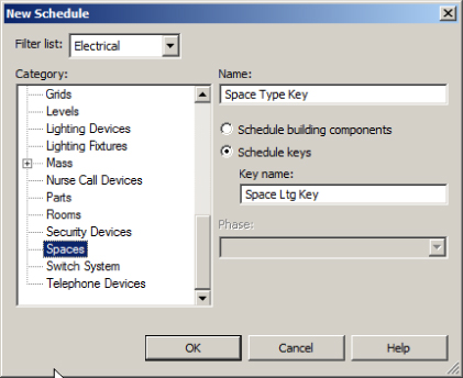
Figure 12.5 Creating a new schedule key for spaces
- Click OK in the New Schedule dialog box to access the Schedule Properties dialog box. Key Name is added as a scheduled field by default, as shown in Figure 12.6.
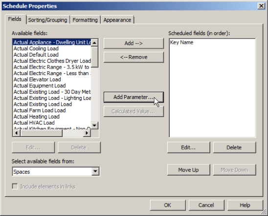
Figure 12.6 Schedule Properties dialog box
- On the left side of the dialog box, select the parameter that you created as the target lighting level for your spaces and click the Add button to include it in the schedule. These are the only two fields required for this schedule, and there is no need to format them or adjust the appearance of the schedule because it is used only for analysis.
- Click OK to create the schedule.
- The schedule does not contain any data rows. At this point, you need to build your key for lighting requirements. Click the Insert button on the Rows panel of the Modify Schedule/Quantities tab and select the Data Row button to create a row in your schedule.
- Change the name of the key in the schedule to that of a common type of building space.
- Add the appropriate lighting level for that type of space in the second column of the schedule, as shown in Figure 12.7.

Figure 12.7 Schedule key data input
- Repeat the process of adding rows, creating space types, and assigning lighting levels until your schedule contains all the space types you require for analysis of your project, as shown in Figure 12.8(a). You can create a comprehensive list in your project template file for use on future projects. Also consider adding the actual Space Type parameter as shown in Figure 12.8(b). Whether you add it in your project template or at any stage of the project is entirely up to you.
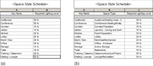
Figure 12.8 Schedule keys with required lighting levels
The purpose of creating the schedule key is to maintain consistency throughout the model and to assign target lighting levels to spaces easily. You can now include the parameter created by the schedule key in your lighting analysis schedule and assign space types to all your spaces without having to select them in the model and edit their properties. Use the drop-down list in the parameter value to select an appropriate type for the space. When you select a space type, the lighting level associated with that type is input into the parameter for the target lighting level of that space, as shown in Figure 12.9. The value for the change calculated by the Lighting Delta conditional format automatically appears in the schedule when a key is assigned to a space.

Figure 12.9 Space lighting keys applied in a schedule
You do not need to assign a type to a space in order to input a value for its targeted lighting level. Simply enter a value in the schedule cell for the target lighting level. Notice in Figure 12.10 that room 107B has not been assigned a space type yet a value has been given for the target lighting level.

Figure 12.10 Calculated values in a lighting analysis schedule
With a target lighting level assigned to each space, you can now determine how well the fixtures you have chosen are lighting the spaces. You can use the Space Lighting Analysis schedule to quickly see the types of adjustments required to meet the target levels. You can even include space parameters such as finishes and make adjustments to them for more accurate results.
Hosting Options for Lighting Fixtures and Devices
Hosting fixtures and devices is important for coordination with other model elements and also reduces the time spent modifying layouts to match design changes. There are a few options for hosting, and you should choose the one that works best for the type of fixtures you are using and the file setup of your project. Face-hosted families are most commonly used because they work in many scenarios, but at times you may need to use an alternative hosting method.
Lighting Fixtures in a Ceiling
Face-hosted lighting fixture families are most commonly used because they can be attached to ceilings in your model or ceilings within a linked file in your model. You can use face-hosted fixtures to represent recessed, surface-mounted, and pendant lights.
The default hosting for a face-hosted family is to a vertical face. To place lighting fixtures onto a ceiling, you need to select the Place On Face option, located on the Placement panel of the contextual tab that appears when placing a lighting fixture family. Lighting fixture families for ceiling-mounted lights should have an insertion point at one corner of the fixture. This lets you align the fixture to the ceiling grid on placement. If the family you are using does not have an insertion point at a corner, place the fixture on the ceiling and use the Move or Align tool to line it up with the grid.
Using the Align tool is great for lining up your fixtures with ceiling grid lines, but it is important that you do not lock the alignment. Face-hosted families do not move with the grid lines when changes are made to the ceiling. Locking the alignment causes constraint errors when the link is updated after the grid has moved. Either way, the lighting fixture stays attached to the ceiling if its elevation changes.
Once you have placed lighting fixtures onto a ceiling, you can copy them where needed. It is important to copy only the fixtures within the ceiling by which they are hosted. If you attempt to copy a face-hosted fixture from one ceiling to another that has a different elevation, you may receive a warning that the new instance of the fixture lies outside its host or that the fixture will remain at the elevation of the original. This will cause the fixture to be in the model without a host or to be above or below the ceiling, which can result in an inaccurate model. If the fixture is not hosted by the ceiling, it will not react to any changes in the ceiling elevation. If the fixture is above the ceiling, lighting calculations will be inaccurate because it will not be inside the space.
The Create Similar command is an easy way to use the same type of fixture family from one ceiling to another. Use this command instead of Copy to duplicate a fixture family in another location. When you use this method, you have to set the hosting option to Place On Face before picking the location of the new fixture. Use the Pick New tool on the Work Plane panel of the Modify | Lighting Fixtures contextual tab to move a lighting fixture from one ceiling to another.
Face-hosted lighting fixture families can be used in areas where a ceiling does not exist. Another choice for placement is to use the Place On Work Plane option. This associates your fixture to a defined plane in the model. Because of the mounting behavior of face-hosted families, it is important to draw your reference planes in the correct direction. Drawing a reference plane from right to left orients the plane properly for overhead lighting fixtures. Drawing from left to right causes your lighting fixture families to be upside down in the model, as shown in Figure 12.11. Based on this, it is my experience that creating your own ceilings for hosting gives the best results. The only thing you need to remember when coordinating is to leave them turned off!
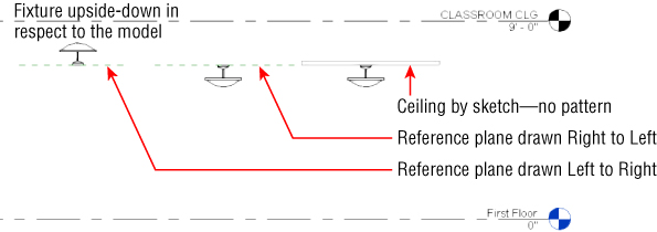
Figure 12.11 Lighting fixtures hosted by reference planes and ceilings
Lighting Fixtures in Sloped Ceilings
Sloped ceilings can of course host lighting fixtures (and anything else that is face hosted, for that matter). Although this is an important feature of Revit MEP, there are some consequences. When the fixture is sloped, the symbolic line representation is no longer visible in a plan view. Figure 12.12 shows the same kind of lighting fixture hosted by a sloped ceiling and another by a flat ceiling. The section view indicates that the fixture is hosted correctly, but the plan view displays the fixture differently.

Figure 12.12 Lighting fixture in a sloped ceiling and on a flat reference plane
The fixture that is attached to the sloped ceiling displays the actual fixture geometry at an angle, whereas the fixture on the level surface shows the symbolic lines used to represent the fixture. This is because symbolic lines can be displayed only in a view that is parallel to the plane in which they are created. There is no way to display these symbolic lines when the fixture is sloped. You would need to either add a note to your documents that identifies the sloped fixtures or add the sloped-fixture representation to your symbol legend.
Another option is to use model lines in your lighting fixture family instead of symbolic lines. Model lines display in plan views if the fixture is in a sloped ceiling. When using this method, consider defining subcategories in the lighting family for the fitting body and sloping symbol. This gives you greater control over the look of your family. You wouldn't, after all, want the symbolic model lines showing up in any sections.
Ceiling Changes
Changes to ceilings may require some management of the lighting fixtures in your model. Face-hosted lighting fixtures maintain their association with the ceiling when there is a change in elevation, but you should also be concerned with any lateral movement, especially with grid ceilings.
Lateral movement can have different effects on your lighting fixtures depending on how the grid was placed into the model. Grids that are placed by automatically locating the boundaries of a room do not affect your light fixtures when they are moved laterally. This is true as long as the movement does not cause your fixtures (which won't move laterally with the ceiling) to be located outside the boundaries of the ceiling. If the architect deletes a ceiling and then replaces it, your fixtures will become orphaned when you get the updated architectural file, and they will remain at the elevation of the original ceiling and will no longer respond to changes in the elevation of the new ceiling. You will have to use the Pick New tool to associate the fixtures with the new ceiling.
Ceilings that are created by sketching the shape of the ceiling have a different effect on your fixtures when moved laterally. If the entire ceiling is moved, your light fixtures will remain in their location relative to the ceiling. If a boundary of the ceiling is edited by dragging it to a new location while in sketch mode, your fixtures will remain where they are located; however, any attempts to place new fixtures into the ceiling may cause them to appear outside the host, and you will receive a warning indicating that the fixture has no host. You can use the Pick New tool then to place the fixture into the ceiling.
Because ceilings tend to move around quite a bit in the early stages of a design, you may want to initially consider hosting your lighting fixtures to a reference plane until the major changes have settled down. At that point, you could move your fixtures into the ceilings by using the Pick New tool. In the meantime, encourage the architects you work with to avoid deleting ceilings and simply alter the ones that exist, when possible. Although people do use this option successfully, there are problems with this workflow, which you saw in Figure 12.11.
Overhead Fixtures in Spaces with No Ceiling
Not every building area for which you need to provide lighting will have a ceiling. Having a space with no ceiling does not mean that you cannot use a face-hosted fixture family. Pendant fixtures can be face-hosted to the floor or structure above, as shown in Figure 12.13.
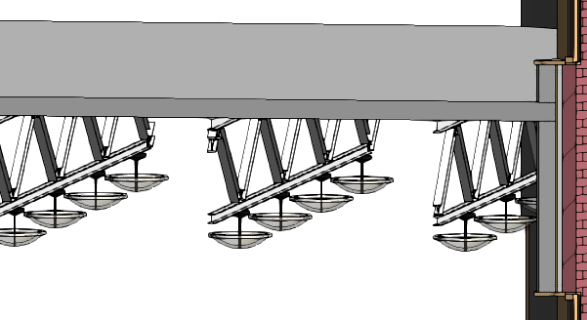
Figure 12.13 Pendant fixtures hosted by structural framing members
You can also use lighting fixture families that do not require a host object. You have to set and manage their elevations manually. These types of fixtures should have a parameter that lets you define the mounting height, or you can use the Offset parameter.
Wall-mounted Lights
Lighting fixtures can be mounted to walls as well as ceilings. In fact, you can place a face-hosted lighting fixture family on practically any surface. However, you should note that any model element categorized as a lighting fixture does not have the ability to maintain its annotation orientation. This means that you cannot use an annotation symbol nested directly in the family to represent the lighting fixture in a plan view when the fixture is mounted to a vertical face. See Chapter 20 for information on nesting an annotation into lighting fixture families that are mounted on vertical surfaces.
One option to work around this shortcoming is to categorize your wall-mounted lighting fixture families as lighting devices instead of lighting fixtures. This gives you the ability to use a symbol, but it could also result in additional effort to control visibility and to schedule these devices along with all your other lighting fixtures.
Your best option, if you want to use face-hosted families and represent wall-mounted lights with symbols, is to create linework in the family that represents the fixture. Then set the visibility of the linework so that it appears only in front and back views. This is necessary because, with the face-hosted family placed on a vertical face, the fixture is seen from within the plan view from the back. The linework must be done with model lines; therefore, they do not react to changes in view scale. This technique is discussed in further detail in Chapter 20, but as shown in Figure 12.14, it is quite achievable.
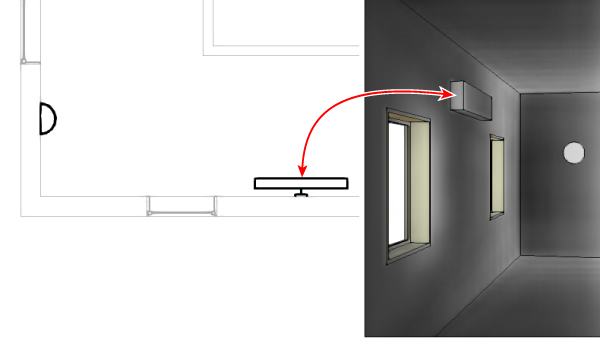
Figure 12.14 Face-hosted fixture mounted on a vertical wall with model lines to represent the fixture
The use of nonhosted families for wall lighting is perfectly acceptable. This requires that you manually maintain the association of the fixtures with the walls because you cannot lock the family to the linked wall. With a nonhosted family, you can use an annotation symbol to represent the lighting fixture in a plan view. This works well for exit lights because the actual fixture is typically not shown; rather, a symbol is shown.
Switches
Using face-hosted lighting switch families keeps your switches coordinated with the locations of their host walls. This does not mean that the movement of doors does not affect the hosting of your switches. Because you cannot constrain your switches to a distance from a door in a linked file, if the door moves so that the switch is in the door opening, you will see the warning shown in Figure 12.15 that the switch has lost its association with the host.
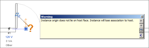
Figure 12.15 Warning that a switch has lost association with its host
You can associate your switches with the lighting fixtures that they operate, provided that the switch family Part Type parameter is set to Switch, as shown in Figure 12.16.

Figure 12.16 Part Type settings of a switch family
To create a switch system, do the following:
- Select a lighting fixture, and click the Switch button on the Create Systems panel of the Modify | Lighting Fixtures contextual tab. This changes the ribbon to the Modify | Switch System contextual tab.
On the System Tools panel of this tab, you have options to select the switch to be used for the system and to edit the system. Editing the system allows you to add or remove elements and view the properties of the switch system. Click the Select Switch button, and select the desired switch in the drawing area.
- After selecting a switch, you can select additional lighting fixtures to be included in the system by clicking the Edit Switch System button. Click the Finish Editing System button once you have selected all of the fixtures for the system.
- To view the system, place your mouse pointer over any item that is part of the system and press the Tab key until dashed lines are shown connecting the fixture(s) back to the switch. This highlights the system elements and indicates their connectivity.
- With the dashed lines highlighted, click to select the system.
A switch system can contain only one switch, so for lighting fixtures controlled by multiple switches, such as three-way switches, you can select only one switch for the system. In the example shown in Figure 12.17, the three-way switch at the top end of the room—marked [1]—would also control the lighting fixtures but cannot be added as part of the switch system highlighted and indicated with dashed lines—marked [2].

Figure 12.17 Switch system
Switches can be assigned an ID by using the Switch ID parameter, which helps identify their relationship with lighting fixtures. This parameter exists in families that are categorized as lighting devices. When you select a lighting fixture and access the Switch Systems tab, you see the ID of the switch associated with that light fixture in parentheses, in the System Selector drop-down on the System Tools panel of the tab.
Creating switch systems is independent of any circuiting of the lighting fixtures and switches. You still need to include the switches in the power circuit for the lighting fixtures if you want to remove them from the Unassigned category in the System Browser. Having as many elements as possible assigned to systems helps improve the overall performance of your model.
Site Lighting
Although you cannot do lighting analysis on site lighting within Revit MEP, a site lighting design can be useful to coordinate loads within panels and create a realistic view of the model from the exterior. Locations of poles, bollards, and other site lighting fixtures can be coordinated with other utilities within the project site. You can also create renderings to get an idea of the coverage of your lighting fixtures on the site.
The Site Plan
If you are working with a civil engineering consultant, it is likely that the engineer is developing the site plan with some sort of CAD software. When the engineer uses a BIM solution, the 3D information (such as elevation points and contours) can be shared with Revit. This is necessary only if you are interested in creating topography within Revit to match the information in the site file. Otherwise, what you require from your civil engineering consultant is just linework that represents the layout of the site. Knowing the layout of parking lots, sidewalks, and major site elements should be enough for you to generate a site lighting design. In one sense, you are working with the site plan in the same manner that you would if you were using a typical 2D CAD system for your design. The difference is that, with Revit MEP, you can use the data within your design to help make decisions and to coordinate with other disciplines and project systems. Ask your consultant for a flat CAD file that you can use throughout the project—in other words, a file that the consultant will update as changes are made to the project site.
The civil engineering and architectural consultants on your project may be sharing files also. At a minimum, the architect would share the building model so that the civil consultant could properly locate the building on the site. Your architect may choose to use the 3D data from the site file to generate a site plan within Revit. If so, you can use this information to create your site lighting layout. Although the architectural site model would give you topographical information, it also is only as up to date and accurate as the architect keeps it.
To get started, do the following:
- Create a view associated with the ground level of your project. Because this is a site plan, the view does not have to contain only lighting system elements, so categorize your view in a manner that makes the most sense for your Project Browser organization. It may be best to create a subdiscipline under Electrical called Site to keep all your site-related views properly organized.
- Set the View Range settings to display the building model properly—that is, as it would appear in a site plan. You can set the Top setting of your view and the Cut Plane setting to an elevation higher than the building so that it appears as seen from high above.
It should not be necessary to use a plan region unless you require the cut plane to be lower in a specific area of the site. If the building is represented in the linked site file, you may choose to not show the linked building model in your view. However, this workflow would mean that you are relying on the civil engineering consultant for an accurate representation of the building outline instead of getting that information from the architectural model.
- Link the CAD file from your consultant into this view. Consider the option for linking the file into this view only, if it is the only place that the site CAD file needs to appear. You could also create a workset for the linked site file so that you can easily control whether it is loaded when your file is opened.
Whatever you decide, be sure to link the file; do not import it. An imported site file can wreak havoc on your model, and you will not be able to update the file automatically when it changes.
- Depending on the origin of the site file and your Revit file, you may have to place the site drawing manually into your view. The site file should contain an outline of the building so you can align it with your linked Revit architectural model. If not, it may be necessary to open the site CAD file and create an alignment-point indicator used to match up with your file.
Site Lighting Layout
With your site plan in place and a view that represents the building in relation to the site, you can now begin to place site lighting fixtures in your model. If you have enabled worksharing in your project, it is best to create a workset for the site lighting plan, or at least for site elements in general. Lighting fixtures that are mounted to the exterior of the building should be included in this workset if they are to be displayed in the site plan view.
A limited number of site lighting fixtures come with Revit MEP, so you likely will have to get your site lighting families from manufacturers' websites or create them yourself. The chapters on content creation in Part 5 of this book will equip you with the skills necessary to create any lighting fixture that your project requires.
The topographic surface from a linked Revit site model does not provide you with a face on which to host your fixtures. You can use the option to place your fixtures on a work plane and associate them with the ground level defined by the building. This works fine for a 2D plan view representation of the site, but if you need to show the site plan in section, elevation, or 3D, you have to adjust your lighting fixtures to match the topographic elevation of their location.
You cannot adjust the Elevation parameter of your lighting fixture families that are hosted by a work plane or level, so you can either use nonhosted families for site lighting or use this little trick: Tab-select the topo surface in the Architectural link file and copy it to the clipboard and then paste Aligned to the same place. Now you can place your external light fittings on the surface of the topo. Either delete it when you have done (the external lights just stay where you put them), or hide the topo from the view. Notice in Figure 12.18 that the elevation of the lighting fixtures is set to match the topography. Even though these families are plane based, they still pick up the topo surface as a host! Face-hosted fixture families were used in this example, since the 3D view is used only for reference.
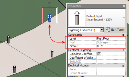
Figure 12.18 Site lighting fixtures
Site Lighting Analysis
Revit MEP can calculate the average estimated illumination of a Space object by using the data from the photometric web file associated with a lighting fixture, but only because the Space object has a volume. Exterior lighting levels cannot be calculated. Most exterior lighting calculation applications are able to import CAD data, so you could export your model to CAD and use the file in your analysis software.
You can, however, use Revit MEP for visual analysis of your site lighting layout. Lighting fixtures that contain photometric web files can display the pattern of light emitted from the fixture in renderings. Creating exterior renderings of your project will give you an idea of the coverage of your lighting fixtures on the site. This can help you determine whether you are using the right type of fixture or whether you need to adjust the number of fixtures used or the spacing of fixtures.
To see the exterior lighting in a rendered 3D view, you need two things. You need to have a surface upon which the light shines, and you need fixtures that contain a light source. If you are using a 2D CAD file for your site plan, you can place a dummy surface at ground level to act as your site surface. Your 3D view should be set with a nighttime sun position so that the sun does not interfere with your lighting. You can display the sun position by using the Sun Settings options on the View Control Bar, as shown in Figure 12.19.

Figure 12.19 Sun Settings tool
When you turn on the sun path, you may see a dialog box with options for displaying the sun path based on the sun settings defined in the Graphic Display Options settings of the view, as shown in Figure 12.20.
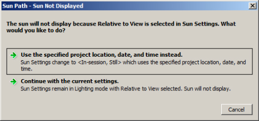
Figure 12.20 Options for sun path display
If you choose the option of using project location and date, the sun path appears in the view, as shown in Figure 12.21. You can adjust the position of the sun by dragging it along the path, or you can click the time shown and edit it manually. The date can also be edited by clicking the text.

Figure 12.21 Sun path shown in a 3D view
To render your site lighting, do the following:
- Click the Show Rendering Dialog button on the View Control Bar of your 3D view. First choose your rendering engine. This is a new feature in Revit MEP 2016 that provides you with the options of NVIDIA mental ray® or Autodesk® Raytracer. Either will give you a photorealistic rendered image and it becomes a matter of preference which you choose.
- Set the lighting scheme as shown in Figure 12.22. It is best practice to try out your renderings in draft mode when you are testing your design because of the amount of time it takes to render a view. Choose the Exterior: Artificial Only lighting scheme.
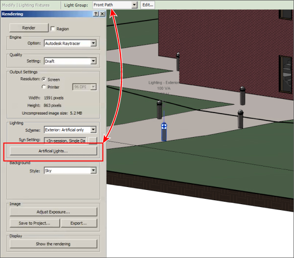
Figure 12.22 Rendering settings for a draft mode view
- You can group lights together and choose which groups to render. This decreases your rendering times because Revit takes into account only the lights within the selected group. To create a light group, simply select a fixture and use the Light Group tool on the Options Bar, as shown in Figure 12.23.
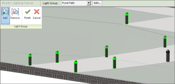
Figure 12.23 Selecting a light group
- Click the Artificial Lights button in the Rendering dialog box to determine which groups of lights will be rendered (see Figure 12.24). You can turn on or turn off entire groups of lights or individual fixtures to decrease rendering times.

Figure 12.24 Choosing which groups of lights to render
- Click the Render button at the top of the Rendering dialog box to generate a rendering of the view.
Once the rendering is finished, you will be able to see the lighting from your fixtures and how the light appears on the site. You can click the Adjust Exposure button to lighten or darken the image for more detail. The rendered view is a useful tool for the visual analysis of your lighting model. If you want to use the rendered view for presentation purposes, you can render the view at a higher level of detail. Figure 12.25 is an example of a rendering showing bollard lighting on a sidewalk with different rendering settings shown inset.

Figure 12.25 Sample rendering of site lighting
The Bottom Line
- Prepare your project for lighting design. The greatest benefit you can receive from a lighting model is coordination with other systems. Properly setting up the project file is critical to achieving this coordination.
- Master It Describe the relationship between ceilings and engineering spaces. How can you be sure that your engineering spaces are reporting the correct geometry?
- Use Revit MEP for lighting analysis. Although the design of electrical systems is usually represented schematically on construction documents, you can use the intelligence within the model to create a design tool that analyzes lighting levels.
- Master It What model elements contain the data required to determine proper lighting layout?
- Compare and evaluate hosting options for lighting fixtures and devices. As a BIM solution, Revit MEP offers multiple options for placing your lighting model elements into your project. These options are in place to accommodate several workflow scenarios.
- Master It What is the default hosting option for face-hosted families? Describe the limitations of representing wall-mounted lights with symbols and how they can be shown in a plan view.
- Develop site lighting plans. Creating a site lighting plan allows you to coordinate with civil engineering consultants as well as with your architect. These plans are also useful for presentation documents and visual inspection of lighting coverage on the site.
- Master It What is the benefit of using nonhosted lighting fixture families for site lighting?