Chapter 24
Fabrication
The Autodesk® Revit® MEP software got a tremendous
boost in the 2016 version with the incorporation of fabrication detailing. This workflow is aimed at construction companies that are required to produce installation-ready documentation. Although this workflow is now integrated into Revit, this chapter explores some limitations and offers ideas on how to get around them.
Fabrication tools are primarily aimed at the fabricator, but they also include tools that people in the consulting world have been waiting for. As this is the first outing, so to speak, for the fabrication toolset in Revit MEP, it is somewhat difficult to judge what will become industry recommendations with tried and tested workflows. So, this chapter simply takes a look at fabrication tools from the ground up, and I will offer my insights on how these tools can be used effectively.
First, Autodesk has provided a separate application to export fabrication information from Revit so it can be imported into Autodesk® Fabrication software. This assumes a process involving a separate designer and fabricator (from different firms). The designer uses Revit, and the fabricator uses an Autodesk Fabrication product: CADmep™, ESTmep™, or CAMduct™. This same application allows the Revit designer to import the fabricator's work for further coordination within Revit with other trades.
The addition of fabrication configurations and the placing of parts directly in Revit assumes the possibility that a single firm may do both design and fabrication. They can elect to create a native Revit model for designing and/or placing parts instead. There may be design decisions or modeling conditions that are understood well enough (or repetitive design work, like for a retail client whose stores are very much the same every time) that they don't require a design pass for sizing duct and fittings initially. They can then export to Autodesk Fabrication so they can create the spooling required to fabricate duct and fittings (or piping).
If you are a fabricator, you may prefer to just use the Autodesk Fabrication suite and then use the Fabrication Import utility within Revit to pass along a model that the design team can link for visual coordination.
If you are an HVAC design firm that doesn't handle fabrication, you will want to export from your design model rather than place fabrication parts yourself. The fabricator can then use your exported data to do their work.
Autodesk has provided options for a variety of real-world situations. It is up to you to decide which approach best serves your needs.
In this chapter, you will learn to do the following:
- Specify fabrication settings
- Use the placement and editing tools
- Edit a fabrication part
Specifying Fabrication Settings
The most important thing you need when starting to use fabrication parts is the content. The content does not automatically download or install with Revit MEP 2016. You can access this content only if you are already an Autodesk Fabrication user or have downloaded the content.
In this chapter I'm working with the default Imperial fabrication content that you will have to download separately. If you prefer, you can use the metric version, or any manufacturer-specific libraries you already have access to. This content is key, because as an installer, you need accurate data. Throughout this chapter I'm assuming that the content is installed; you need to incorporate it into your project file or project template.
As with any project or template, a best practice is to not load everything into it, including fabrication parts.
However, these elements are stored in a different format than regular Revit families (ITM format rather than RFA), and so while the overall overhead may not be as great as with families, there still isn't any point in loading a cable tray configuration if you are a mechanical contractor. You can load in other services at any time during the project if the need arises, and I will cover that later in this chapter.
The Systems tab provides a tool for accessing fabrication parts, and below it is an arrow (see Figure 24.1) that you can click to open the Fabrication Settings dialog box.

Figure 24.1 Click this arrow to open the Fabrication Settings dialog box.
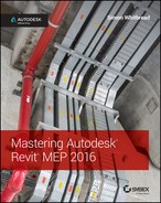
Begin by choosing the content from the Fabrication Configuration drop-down list, as shown in Figure 24.2. Selecting Imperial Content gives you a list of unloaded services.
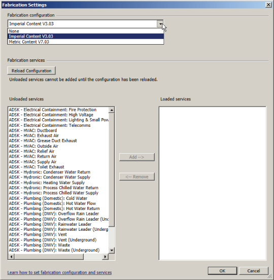
Figure 24.2 Unloaded Services list
Choose each service you want to load and click Add to move it to the Loaded Service list. When you've finished selecting your services, click OK. Notice that if you go back to the dialog box any time after that, everything appears to be locked. You cannot add or remove services from the configuration unless you click the Reload Configuration button, as shown in Figure 24.3.

Figure 24.3 Click the Reload Configuration button.
Note that although you can remove a fabrication service, once there are elements of that service within the model it cannot be removed. The implication for worksharing is this: if fabrication services are to be added to a model, it is strongly advised that all users relinquish and save to central. One person should make the necessary changes by adding or removing services and then synchronizing. All other users should then create a new local file. Refer to Chapter 3, “Worksets and Worksharing,” for more information.
Placing Fabrication Parts
When using the fabrication tools, it quickly becomes apparent that the relationship between native Revit objects and these new fabrication parts is disjointed. My view is that this first inclusion of the fabrication tools into Revit is merely a glimpse of what may become a much better feature in the future.
Let's first take a look at what the tools won't do so we can then focus on the expected workflow:
- No Conversion Tools You cannot convert from native Revit components to fabrication parts. The conversion takes place via Autodesk Fabrication software.
- No Design Information None of the fabrication parts hold design information like air or liquid flow; likewise, you cannot size duct or pipe systems using the Revit sizing tools.
- No Interference Checking You cannot check for clashing elements between fabrication parts and other native Revit objects using the Revit Interference Check tool. You have to rely on other software like Autodesk® Navisworks® for that task.
- Fittings and Accessories Are Not “Automatic” Because you are dealing with fabricated elements, the parts do not support “breaks into” actions like duct and pipe. Instead, you have to place every object, one step at a time, sequentially. You will see this later in an exercise.
- Inability to Assign Keyboard Shortcuts You are not able to assign keyboard shortcuts to the individual fabrication tools. You must use the Fabrication Parts dialog box (the default is for this is PB).
There are some clear directives on why a minimalist approach has been taken for this release; stability and performance are the most crucial. There are others, such as conversion and design information. The expected workflow is that the contractors working on this part of the design would normally develop the design layout using manufactured objects that may not conform to the original layout. Thus, although the route may be similar, the design intent information may not be necessary for the contractor. Still, to achieve a true building information model, there should be a way to contain some of this data to allow you to give the end customer all necessary data.
With regard to checking for interference, the expected workflow is to use Navisworks as the collaboration and checking tool. In addition, you will notice in the Fabrication Parts dialog box that some parts (mostly under the group End Of Line Equipment) are displayed in a halftone. This is because those specific parts are not currently supported by the fabrication tools, so you would use native Revit objects instead. You will see an example of this in an exercise later in this chapter.
So now we have what identified what isn't supported; let's concentrate on what we can do.
You already saw in Figure 24.1 how to access the Fabrication Parts dialog box. Now that it is active, you can see the parts available for each service loaded. The parts are subdivided into groups, as shown in Figure 24.4.

Figure 24.4 MEP Fabrication Parts dialog box
As you can see, there are a collection of objects that you select from and then place. For example, select the item Supply Air Straight Duct, and then choose the appropriate properties from the Properties palette. Some of these are similar to those in standard Revit elements like Offset and Reference Level, as you can see in Figure 24.5 (1). Others are more specific to fabrication parts, such as Part Material (2), More Parameters (3), primary dimensions (4) and length options (5), whereas the group Fabrication Product Data (6) is defined in your external fabrication software.

Figure 24.5 Fabrication Properties palette
When you select Edit Part, a dialog box appears, as shown in Figure 24.6. Here you can change additional properties—for example, dimensions in the Dimensions tab and connector types in the Connectors tab. Unlike their native Revit counterparts, once a fabrication part is placed and connected to another object, some, if not all, of the dimensions are locked. This is because the object is now representing a manufactured object rather than a design object, which has more flexibility.
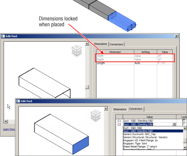
Figure 24.6 Editing placed parts
Fabrication parts will, however, connect to native Revit object connectors from all the MEP disciplines. This means pipe and duct fabrication parts will connect to mechanical and plumbing fixtures, whereas electrical containment parts will connect to power boards and other electrical equipment.
Another nice feature is the ability to connect to native Revit system families such as ducts, pipes, and cable tray. This does mean that fixed equipment from the design can continue to be used, taking the model from a conceptual form into one that is almost ready for handover to the end customer.
In the next exercises, you'll see the power of fabrication parts by creating examples for mechanical, electrical, and plumbing. The electrical example should be interesting to anyone, including both designers and fabricators, because it demonstrates a workflow that, for designers, has been almost unachievable in Revit MEP until now.
Creating a Fabrication Layout
Now that we have reviewed the process of placing fabrication parts, it is time to put your knowledge into practice with the following simple exercise:
- Open the file
RMEP2016_Ch24_Simple Fabrication.rvtfile found at this book's web page,www.sybex.com/go/masteringrevitmep2016. - Zoom into the floor plan 1-Mech so you can see the layout easily.
- Click the arrow to open the Fabrication Settings dialog box, as shown earlier in Figure 24.1, and add all the HVAC services; then make sure you can see the MEP Fabrication Parts dialog box.
- As shown in Figure 24.7, select ADSK - HVAC: Supply Air from the Service drop-down and select Rectangular from the Group drop-down.

Figure 24.7 Setting the fabrication parts service
- Select the straight section of duct, and before placing it, change Length Option from Auto to Value and Length to 6'-0” (1800 mm), as shown in Figure 24.8. In this example we want to connect to the VAV unit (in Space 3) on the right of the model. As you hover over the mechanical connector, the duct fabrication part will want to snap to the connector. Even though the default offset for the duct is 0'-0” (0 mm), the fabrication duct connects to the VAV at 10'-0” (2500 mm), as shown in Figure 24.9.

Figure 24.8 Changing Length Option to Value and Length to 6′-0″
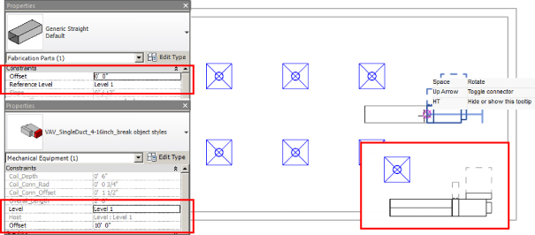
Figure 24.9 Connecting to the VAV unit
- You now need to add a transition. Select the appropriate tool from the dialog box. Figure 24.10 shows the properties. Change Main Secondary Width to 14” (350 mm) and Main Secondary Depth Option to Equal; this will match the previous duct section.

Figure 24.10 Changing transition settings
- Repeat steps 5, 6, and 5 again so you have a straight duct run with a 6'-0” long, 14”×12” duct (1800 mm long, 350 mm×300 mm) and a 4'-0” long, 12”×12” duct (1200 mm long, 300 mm×300 mm). End the run with a cap.
- Final connections are a combination of fabrication parts and native Revit MEP flexible duct. Change the fabrication group to Round Bought Out and select Flat Shoe.
- From the Properties palette, change the Product Entry size to 8” (200 mm). Notice that when you place the shoe fitting, Revit displays an alignment dashed line by extension to the Air Terminal above, as shown in Figure 24.11.

Figure 24.11 Placing a flat shoe
- Repeat the previous step for the next two air terminals and then connect using the Flex Duct tool from the Systems tab.
- With the top row complete, use the Mirror tool from the Modify tab to complete the layout, as shown in Figure 24.12.

Figure 24.12 Using the Mirror tool
You should see from this exercise that the toolset for fabrication detailing is a straightforward point, pick, and click workflow that is easy to use. But in this release, there is no translation between native Revit and the fabrication tools. I want to emphasize this shortcoming—but, like most good things, I'm sure the toolset will mature.
Editing a Fabrication Layout
So, now that you are familiar with adding the services and creating a basic layout, I want to take you through some of the other tools and components and show how you get to the end fabrication layout. To do this, let's take a look at Figure 24.13.

Figure 24.13 Design and fabrication layouts
The top part of the image you already saw in Chapter 10, “Mechanical Systems and Ductwork,” and the bottom shows the completed fabrication layout. The only original objects from the design model are the air terminals and the VAV unit. Everything else has been deleted in order to place the fabrication parts. Figure 24.14 shows the starting point.
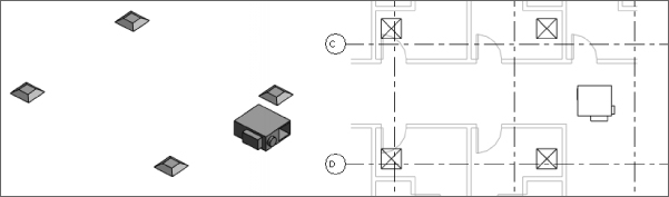
Figure 24.14 Our model ready for fabrication
Starting with the Square to Round connector, note that there are five instances in this layout: one is for the VAV connection, and the other four go to the air terminals. Notice that when you hover over one of the connectors, the Main Primary Width and Main Primary Depth values automatically change to suit the existing connector. What you need to do is manually change the Main Secondary Diameter and Length before you place the transition. This is because once the fabrication part is placed and connected to another part, there is very little you can do to it. The connected elements are effectively frozen. Figure 24.15 shows this process. First, you select the fabrication part from the dialog box. In the top part of the image with the connector not yet placed, the dimensional parameters are at their default settings. After editing Main Secondary Diameter and Length, you hover over the air terminal and the other parameters match the connector sizes.

Figure 24.15 Changing parameters
When placing fabrication parts, you need to take into consideration a multitude of scenarios:
- Part Type Once placed, one part type cannot be changed to another. Notice that if you click Edit Type in the Properties palette, there is only one type (Default), which cannot be duplicated.
- Length In a straight run of duct, you will not be able to change the length of any one piece of duct. However, using the Tab-select method to highlight an entire run, you can use the Optimize Lengths tool, which will replace the run with default lengths of duct and one custom length, as shown in Figure 24.16.
- In-line Equipment Do you need to add any dampers, attenuators, fans, or so forth? If so, you need to add these into your layout in a sequential order, because, as mentioned earlier, fabrication parts do not have a “break into” function like native Revit MEP duct and pipe accessories.
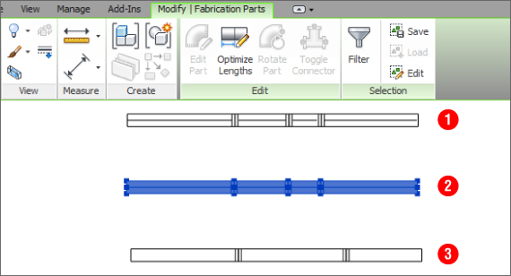
Figure 24.16 Optimizing the length of the run
When you are placing a fabrication part, such as a bend, chances are that it will not be pointing in the direction you want. On the Modify | Place Fabrication Part portion of the ribbon, you have five options:
- Edit Part I described this option earlier, in the section “Placing Fabrication Parts.”
- Rotate Part As its name suggests, you can rotate the part, either by using the icon on the ribbon, by pressing the spacebar while inserting the part, or by using the onscreen toggle that matches the ribbon icon.
- Toggle Connector This is especially useful if you are placing a connected part that has multiple connections and the default is not the one you want to use.
- Smart Snapping This option allows you to snap to connectors without having to worry about whether you are selecting a line endpoint.
- Show Help Tooltip This option provides a heads-up display—you may want to turn it off after a few hours' use.
With the part rotated into position, click to place, as shown in Figure 24.17.

Figure 24.17 Rotate on placement
One circumstance in which editing a fabrication layout does take some practice is placement of boots and saddles on round duct. There are several things going on at the same time: position, orientation, and size. Let's take the curved boot as an example. The default settings for Product Entry size are 8”×3” (200 mm×75 mm), whereas in the example the main duct run is 14” (350 mm) and the final flex is 8” (200 mm). When you select the Product Entry parameter, a large number of possibilities are available. To make them easier to understand, take advantage of the new filter option and start typing in the required size. In Figure 24.18 you can see that in the filtered list on the right it is much easier to find the correct size combination.

Figure 24.18 Selecting the size
With all the fabrication parts placed, all you need to complete the model is the flexible duct available from the Systems tab. Figure 24.19 shows the completed layout.

Figure 24.19 Completed fabrication layout
The process for placing fabrication parts for pipe and duct layouts is identical. With that in mind, what follows is another short exercise focused on electrical containment (cable tray) instead (shown in Figure 24.20). I know from my experience working with consulting engineers that they have been almost begging to be able to do this.

Figure 24.20 Cable containment
- Open the file
RMEP2016_Ch24_Electrical Dataset.rvtfile found at this book's web page. - Open the 3D view Cable Tray and Conduit and the section Section 4. Tile the views.
- Activate the section and from the Fabrication Parts dialog box, choose the service ADSK-Electrical Containment: High Voltage and the group Ladder, and then select a straight run. Before placing, make sure you change the length to 2'-0” (600 mm), as shown in Figure 24.21.

Figure 24.21 Be sure to change the Length value.
- As shown in Figure 24.22, select the 90 degree Outside Riser and connect to the vertical ladder in the 3D view.
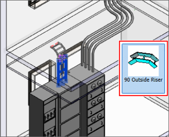
Figure 24.22 Placing the outside riser
- Next, you want to place an equal tee, although on placement its orientation may not be correct. Here you can use the Toggle Connector tool, or the up arrow on your keyboard, to rotate the part and then click to place, as shown in Figure 24.23.
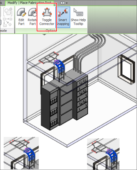
Figure 24.23 Placing an equal tee
- Add two straight sections—make sure the length is set to 8'-6” (2550 mm)—and then a 90 Inside Riser to the right-hand end of the run.
- Add a 7'-0” (2100 mm) vertical straight run, and then another equal tee, making sure the connector is pointing toward the window. Finally, add a straight run that passes over the window, as shown in Figure 24.24.
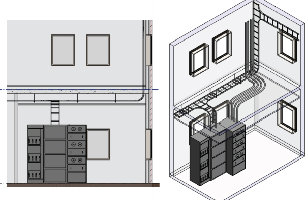
Figure 24.24 Completing the ladder
- The final part of this exercise is to add ladder supports. In the Parts dialog box, change the group to Supports. Notice that as you pass over the ladder, the support only picks out straight, horizontal runs, and when you place a support, it will automatically connect to any structure overhead.
The Bottom Line
- Specify fabrication settings. Fabrication configurations have to be loaded into each project. It may be worthwhile to do so in one or more of your project templates.
- Master It Should you load all the fabrication configurations into your template file?
- Use the placement and editing tools. The placement tools require time and practice to master, especially the connections to native Revit elements and connectors.
- Master It Is it possible to change the length of a straight run of duct after it is placed?
- Edit a fabrication part. When placing fabrication parts, you must choose the sizes you need before placement.
- Master It Where can you change the size of a circular duct curved boot?