
Chapter 4
Project Collaboration
Since engineers and architects started working together on building projects, an integrated project delivery has been the ultimate goal. The goal of consultants working together as seamlessly as possible is made more achievable by using a building information modeling (BIM) solution such as the Autodesk® Revit® MEP 2016 platform. Many are quick to believe that using a BIM solution automatically means coordination and integration, but the truth is that developing a building information model is only part of the process. You can build a 3D model and even put information into it, but it is how this information is shared and coordinated that defines an integrated project.
Revit MEP enables you to interact with the project model in a way that you can conceptualize the design as a whole, even if you are working on only pieces or parts. You do not have to work for a full-service design firm to participate in a project that results in a complete model. Architectural, structural, and MEP engineering systems can all come together regardless of company size, staff, or location. It is the sharing of computable data that makes for an integrated project delivery. Owners and contractors can also participate in the process. In fact, anyone who has any input into the design decisions should be included in and considered part of the project team.
Zooming in from the big picture a bit, you need to focus on your role as a project team member. You can be an effective player in the process by ensuring that the data you are sharing is usable, accurate, and timely. With a firm understanding of how Revit manages your information, you can develop some good practices and standards for collaborating with your project team.
In this chapter, you will learn to do the following:
- Prepare your project file for sharing with consultants
- Work with linked Revit files
- Coordinate elements within shared models
- Work with files from other applications
- Set up a system for quality control
Preparing Your Files for Sharing
In Chapter 3, “Worksets and Worksharing,” you looked at ways to set up your project file to allow members of your design team to work collaboratively within their specific design disciplines. Although one goal is to make yourself more efficient and accurate, you must also recognize the importance of setting up and developing the project file in a way that you can easily share the design with your consultants. It is a good idea to consider whether the workflow or process you are setting up will have an adverse effect on other project team members.
A Revit project file does not have to be set up as a central file in order to share it with others. If there is no need to establish worksets in your project, you can simply save your file as the design develops and share it when necessary. This is the simplest type of Revit project file to share, because there is no concern for receiving a local file by mistake or a file that is not updated with the most current design changes. As with all files that will be shared among team members, it is a good practice to name the Revit project file in a manner that clearly indicates the systems that it contains, such as MEP Model.rvt or HVAC.rvt. This makes linked files easy to manage and reload when updates occur.
If your Revit file has been set up with worksets, there are other considerations for sharing the file with your consultants. You should take care to realize that the decisions you make when setting up your worksets can affect those team members who need to visualize and coordinate with your design elements.
The first decision comes when you create your worksets. In the New Workset dialog box, you have the option of naming your workset, as shown in Figure 4.1. The name you choose should be descriptive so that others will know the types of items included in the workset. Using a descriptive name is also helpful to your consultants who have the ability to see what worksets are in your file. The other part of this dialog box offers you the option to make the newly created workset visible in all your model views. If you choose not to make the workset visible in all views, you will have to make it visible in each view that you want to see it in via Visibility/Graphic Overrides settings.
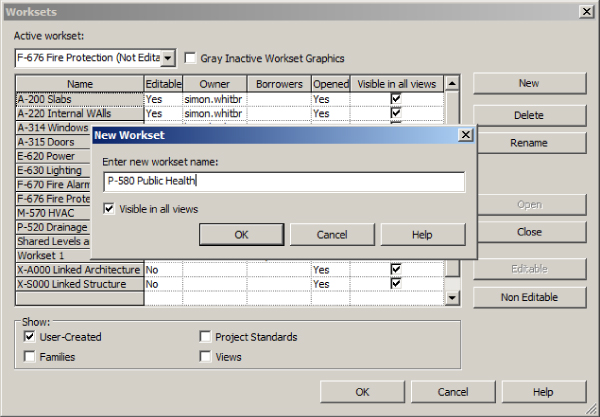
Figure 4.1 New Workset dialog box
When you are creating your worksets, you may want to consider the Revit files that you will be linking into your project. It can be very useful to create a workset for each linked Revit file so that you can control not only each file's visibility but also whether a file is loaded into the project. Because you have the ability to choose which worksets to open when you open your file, you can determine which linked files will be present and visible when your file is opened. This can increase your productivity by improving file-opening and model-regeneration times. It also helps by not having to load and unload the links, which can cause problems with hosted elements. When you do not open a workset a linked file is a part of, the linked file is still part of your file; it's just not visible or “present” in your session.
The makeup of your Revit project template file has a lot to do with the preparation for sharing your file with others. Consider carefully the content that you put into your template. It is tempting to dump your whole family library into the template in order to have everything right at your fingertips, but this makes for large files that are not as easily shared. Once you have worked on a few projects, you will be able to determine what is really necessary to have in your template file.
There is no denying that Revit files can get to be very large. Purging any unused items from your files prior to sharing them is helpful in keeping file sizes to a minimum, but you should use this feature with caution.
Because of the size of the files, sharing them among consultants via email is not a recommended practice. Most people do not have the capacity to receive large files via email. Using FTP is one of the common practices for file sharing. Also, certain third-party applications are designed specifically for project collaboration.
It is usually the primary design team that establishes the file sharing means and gives all teams access to upload and download files. Each consultant should have at least one designated person to manage the transfer of files for their team. This person should be responsible for making sure that the most current files have been shared. The frequency of updated files being posted to the site should be determined early on during a project kickoff meeting (you are having those, right?) and can be changed depending on the needs of the project. At a minimum, you should prepare to post your files once a week during active development. This will keep your consultants up to date with the progress of your design.
If you have enabled worksharing on your project, it is important that you send your central file to your consultants, not a local file. This ensures that they are receiving a file with updated information from all your team members. Consider a workflow that includes having all team members synchronize with the central file and then creating a new project file by using the Detach From Central option.
You also have the option in Revit MEP to remove worksets. Your consultants will, of course, be able to do this for themselves. But remember, if you have used worksets to control object visibility, the settings will be destroyed if worksets are removed. Of course, you gave the consultants that information at the project kickoff meeting, didn't you?
Working with Linked Revit Files
Revit MEP not only gives you the power to model and document your design but also enables you to coordinate with the designs of your consultants directly in your project file. This concept is not new to the world of digital documentation. It is the same workflow that occurs in 2D CAD: you receive a file from your consultant, overlay it into your file, and watch as it updates during the changes to the design.
The difference with Revit is in how much more you are able to coordinate by receiving a model that is not only a graphical representation but also a database with computable information. Some of the terminology is different when working with Revit. Instead of external references (X-refs), we call the files that are loaded into our project linked files. The following sections cover some best practices for loading, managing, and viewing links that are Revit RVT files. Later in this chapter, and again in Chapter 5, “Multiplatform Interoperability: Working with 2D and 3D Data,” you will learn about files of other CAD formats.
Linking Revit Files
When you are ready to bring a Revit file from a consultant into your file, you may want to first do some maintenance on that file. Copy the file you have received to your network. If the file you are receiving is a central file, you should open the file by using the Detach From Central option, as shown in Figure 4.2.
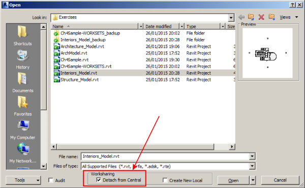
Figure 4.2 Using the Detach From Central option
As mentioned earlier, you have the ability to remove worksharing from a project file when using the Detach From Central option. The dialog box shown in Figure 4.3 provides options for preserving worksets or removing them from the file.
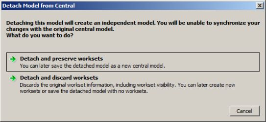
Figure 4.3 Detach Model From Central dialog box
Use caution when removing worksets from a file because this action can affect the visibility and display of many types of elements. When you are using a consultant's model, this may be less important if you are concerned only with having that model linked into yours. Preserving the worksets, however, may make it easier for you to control the visibility of systems or specific components within the linked file. You may consider purging unused content and deleting views from a linked file to reduce file size; however, you will have to repeat the process each time you receive an updated version of the file.
When you open a file with the Detach From Central option selected, the file becomes a temporary project file stored in your computer's RAM. You are the owner of all the worksets in the file if you have chosen the option to preserve worksets. Once the file is open, you can save it to the location from which you will load it by using the Save or Save As command. The project isn't an actual file yet, so Revit expects you to provide a location and filename. Using the same location as your project file will make it easier to manage all your linked files. If the filename does not suit your standards, you can give it any name you want. However, the location and the filename that you choose should remain the same throughout the life of the project. It is best to avoid overwriting a file with the same name by using Save As, so when you download the file and put it on your network, you may want to rename it prior to opening it. You should also avoid downloading it directly to the directory in which the working linked file resides, especially if you are not changing the filename. You do not want to overwrite the linked file before you get a chance to clean it up.
You then need to relinquish your ownership of all the worksets and synchronize the file again. This ensures that the file you have received from your consultant is not attempting to coordinate with local files from another network. If the file you are linking is not a central file, you do not need to open it because there will be no worksets or local files associated with it, unless you are opening it to purge items and clean up views.
There is no need to keep an archive of all the files being sent to you. Revit files can be very large, so keeping an archive will quickly use up storage space. When worksharing has been enabled in a file, Revit keeps a backup log of the file. The Restore Backup button on the Collaborate tab allows you to roll back changes to the file. So if you require a previous version of your consultant's model, you could ask that consultant to save a rolled-back version of the file and send it to you. If you would like to keep archived versions of the project, you need to explore such avenues as cloud storage, external hard drives, or DVD to save storage space on your network or hard drive. The option you choose can be dependent on cost, length of time required for storage, and future retrieval methods.
Once the maintenance has been done on your consultant's file, you are ready to link it into your file. The first thing to do when bringing any type of file into your project is to make sure you have the appropriate workset active (if you have enabled worksharing). In a project file with multiple MEP disciplines, every discipline will need to use the architectural model for background and coordination, so you should place it on a workset that is common to all users. The Shared Levels and Grids workset is a good option if you have not created worksets specifically for linked files. This workset can be visible in all views without causing too much extra work to control the visibility of other elements within the workset. Let's first take a look at linking in the architectural model. Here are the steps:
- With the appropriate workset active, click the Link Revit button on the Insert tab. Browse to the location of the file you saved after receiving it from your consultant. The position of the linked file is crucial to coordination, so before you click Open, you must determine the positioning of the file by using the Positioning drop-down menu at the bottom of the Import/Link RVT dialog box. Figure 4.4 shows the six options for placing the linked file into your project.
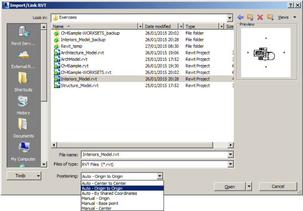
Figure 4.4 Positioning options for linked Revit files
The three Manual options allow you to place the model into your file manually by using an insertion point from the origin, the center, or a specified base point of the file you are linking. These options are rarely used because they require you to locate the model manually, which can be difficult without a common reference point in both files.
The automatic options are more commonly used, and each has a specific function:
- Auto – Center To Center This option links the file from its center point to the center point of your file. The center point is determined by the location of the model objects within the file—the center of the overall extents that those objects define in each file. This option should be avoided unless you and your consultants have a coordinated center point and the makeup of the model will prevent that point from changing.
- Auto – Origin To Origin This is the best option to use. The origin of the linked file will not change if the model changes size or shape, or even if building geometry is moved or rotated, so you will be able to stay coordinated with the building when major position changes occur.
- Auto – By Shared Coordinates This option is only valid when shared coordinates have been established already. As a rule, Origin to Origin is much more likely and appropriate. This is most commonly used on projects that have multiple buildings because it enables you to keep the relationship between buildings coordinated. If you link in a file that is using shared coordinates, you can use the same coordinates for your file. This is only relevant when someone has taken extra steps to establish a shared coordinate system. Routine linking of consultant models at this stage of the book is outside this chapter's scope.
Always take care when linking a Revit file and make sure you check the positioning setting. Revit will remember the last setting you use in the current session. When Revit is started, the default is Auto – Origin to Origin.
- Once you have chosen a positioning option, you can choose options for loading worksets, similar to when you open a file that contains worksets. Just click the pull-down menu next to the Open button. You can open all the worksets or specify which ones you want. If you specify worksets to be open, they are the only ones whose components will be visible when the file is loaded.
- Click the Open button to link the file into your project. The linked model file then appears in your file at the location determined by your Positioning option. If you selected a Manual option, you will need to click a position in the view window to place the linked model.
- Once the linked model is in the correct position, you want it to stay there, so before you do anything with the linked model, choose one of the following options to prevent users from accidentally moving the whole building when clicking and dragging items during design.
- Select the linked model, click the Pin button that appears on the Modify panel of the Modify | RVT Links tab, and choose the Select Pinned Elements toggle (1) on the status bar, as shown in Figure 4.5.
- Alternatively, click the Select Links toggle (2), as shown in Figure 4.5. Either way, you are now unable to select and move the linked file.
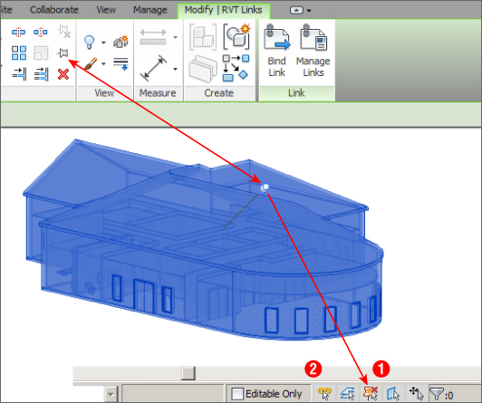
Figure 4.5 Pin and Do Not Select
- Repeat steps 1 through 4 for all the files you need to link into your project. Once you have all your Revit links in place, synchronize your file with the central file, or if your file is not using worksharing, simply save it.
Using Shared Coordinates
Using shared coordinates is a useful way to keep several linked files in the correct location and orientation within your project file. The key to using shared coordinates is establishing which file will determine the coordinate system, and generally speaking, it is the architect's responsibility to do this. Every Revit project has two coordinate systems: one determines the project coordinates, whereas the other defines the real-world coordinates.
The project base point of a project can be viewed by turning on its visibility, which is located under Site in the Model Categories tab of the Visibility/Graphic Overrides dialog box (see Figure 4.6). Site is an architectural category, so you must set the filter list to view Architectural categories.

Figure 4.6 Project base point visibility settings
When you select the project base point indicator in a view, you see the coordinates established for the Revit project. The N/S, E/W, and Elevation coordinates can all be set by selecting and editing the value along with the angle of the project relative to True North, as shown in Figure 4.7.
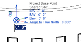
Figure 4.7 Editing a project base point
The paper clip icon allows you to move the entire project or to move only the project base point location. When the project base point is “clipped,” moving it is the same as using the Relocate Project tool. This does not affect the model as it relates to the project coordinates, but if you are using shared coordinates to align with linked files, it will cause you to be out of alignment.
Moving the project base point when it is “unclipped” causes the project coordinate system to move in relation to the model. This changes the shared coordinates of the project base point. However, the shared coordinates of the model components do not change.
So, although you can, it doesn't mean you should, and it's better to leave the project base point alone.
You can acquire the coordinates of a linked file. Use the Coordinates tool on the Project Location panel of the Manage tab, and select the Acquire Coordinates option. This allows you to select a linked file in the drawing area and sets your project coordinates to match those of the linked file. Figure 4.8 shows the settings for a project prior to acquiring coordinates (left) and the settings after the coordinates of the linked model are acquired (right). This ensures that both files are working off the same coordinate system and is of most use when collaborating in software such as the Autodesk® Navisworks® program. Notice that the project base point is in the same location in relation to the building geometry.
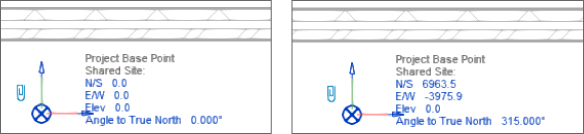
Figure 4.8 Settings before acquiring coordinates (left) and after acquiring coordinates (right)
The survey point of a project can be used to create a relationship to survey data that is also more often than not in a Revit format to begin with and is established by either the architect or the civil engineer. The survey point can be made visible by using the Visibility/Graphic Overrides dialog box, as shown in Figure 4.9. However, if the survey point has not been set up yet by the architect or the civil engineer, there is no advantage to doing so until you have word from them. Once the survey point has been established, using it allows the engineer or architect to export using shared coordinates later so their model can be coordinated in software like Navisworks more easily.
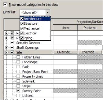
Figure 4.9 Survey point visibility settings
The survey point appears as a triangle in the view. Moving a “clipped” survey point changes the position of the shared coordinate system in relation to the model and the project coordinate system. So, for example, if you have your survey point set to 0,0,0 and you move it, you are changing where 0,0,0 is located in your project. This will affect the location of your model components in relation to a linked file with which you are sharing coordinates.
Moving an “unclipped” survey point moves the point. The icon becomes a marker that no longer indicates the shared coordinate origin; it indicates its position relative to the origin of the shared coordinates system. The shared coordinate origin remains fixed. The survey point icon starts reporting coordinates that indicate its X/Y offset from that origin in relation to the shared coordinate and project coordinate systems. This does not change the shared or project coordinates of the model—it simply changes the location of the survey point icon. This allows you to move it to identify a specific location established by a linked file without changing the shared coordinates.
Managing Revit Links
Throughout the design process, you will want to keep up with the many changes occurring in the files you have linked into your project. Revit does not always automatically update your file with changes made in the linked files. The only time updates occur automatically is when you open your project file and the linked files have been updated by their source. If you are in a working session of Revit and one of your linked files is updated, you will have to reload the link manually to see the update.
Updating files from your consultants requires the same process you used when you first received the files, except you do not have to insert them into your file again. Download the new file from your consultant, and apply the maintenance procedures discussed in the previous section. Be sure that you overwrite the existing file with the new one and avoid changing the name.
After you have updated the files in your project folder, you can open your project file. If you are working in a local file, you should synchronize it with the central file as soon as it is finished opening. This will ensure that the central file contains the updated linked file information.
Sometimes new versions of the files you are linking become available while you are working in your project file. If another user has updated the linked files and synchronized them with the central file, when you synchronize with the central file you will also get the reloaded, updated link file (which is a workflow new to Revit 2016). This standardizes the workflow for loading and unloading links for all users when they synchronize.
To reload a linked Revit file, click the Manage Links button on the Manage tab (it's also available on the Insert tab or by right-clicking on the link file in the Project Browser). This opens the Manage Links dialog box, which enables you to manage the files you have loaded into your project (see Figure 4.10).
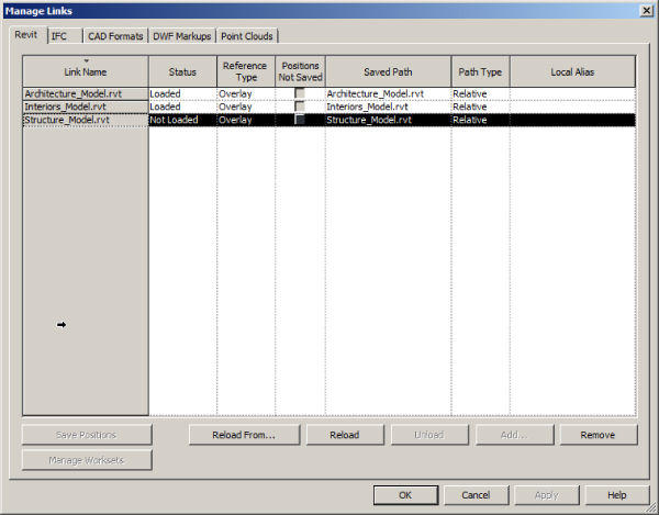
Figure 4.10 Manage Links dialog box
The Revit tab of the Manage Links dialog box lists all the Revit files linked into your file. Here, you can determine whether the file is an attachment or an overlay. This is the same behavior found in external references in the Autodesk® AutoCAD® platform. An attachment will need to travel with the file, whereas an overlay is only for the file to which it is linked. If a file you are linking in has other Revit files linked to it as overlays, you will see a dialog box indicating that the overlaid files will not link into your file when you load or reload the link. This allows you to have the architectural file linked into your file, and your file linked into the architectural file, without duplicating either model. In other words, your file does not come back to you when you link in the architectural file. The default setting for linking files is Overlay, because this is the best choice.
The Save Positions button in the lower-left corner of the dialog box is used when your project is using shared coordinates. If you move a link within your project, you will receive a warning dialog box with options for saving the new location, or you can use the Save Positions button.
Other buttons allow you to unload, reload, and remove links from your file. Once a link is removed, you cannot get it back by using the Undo feature; you will have to load the link back into your project. The Reload From button allows you to reload a link that may have moved to a new location on your network. You can even replace it with a different file altogether.
You can also use the Project Browser to manage the files linked into your project. All linked Revit files are listed at the bottom of the Project Browser. Right-clicking a link provides a menu with quick access to link-management tools, as shown in Figure 4.11.
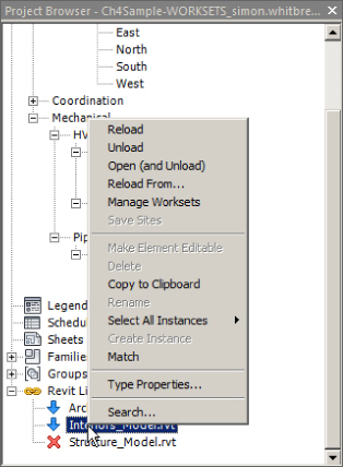
Figure 4.11 Quick access to link-management tools from the Project Browser
Notice that one option is Select All Instances. You can have multiple instances of a linked file in your project by selecting the link in the drawing area and copying it.
Controlling Visibility of Revit Links
When a Revit file is linked into your project, it is treated as one element—a linked model. Linking in the architectural model does not mean that you now have walls, doors, and windows in your project model. The model is seen as a single linked file. You do, however, have control over the visibility of the individual components that make up the linked model as well as the entire link itself.
When you link in a Revit file, a new tab appears in the Visibility/Graphic Overrides dialog box. This tab lists the linked Revit files and allows you to turn them on or off. If you have multiple copies of a link, they are listed beneath the name of the link, as seen when you click the + next to the link name. Each copy can be given a unique name for easy management. There is also a check box for setting the link to halftone. (This is not necessary for views set to mechanical, plumbing, or electrical disciplines because Revit automatically applies halftone to the architectural and structural elements in these discipline views.) This tab is useful for turning links on or off in views as needed during design, and the settings can even be applied to view templates. The Underlay column allows you to display the linked file as defined by the Halftone/Underlay settings established for the project.
You can also control the visibility of components within the linked Revit file. By default, the components in the Revit link will react to the settings for visibility that you apply to your view. So, if you were to turn off the Doors category in your view, the doors in the Revit link will also turn off in that view. The same is true for any overrides you may apply for line weight or color. Figure 4.12 shows that this behavior is indicated in the Visibility/Graphic Overrides dialog box as By Host View.
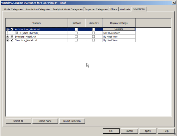
Figure 4.12 Linked Revit file Display Settings
Clicking the By Host View button for a link opens the RVT Link Display Settings dialog box. This is similar to the Visibility/Graphic Overrides dialog box, but it is specific to the selected Revit link. The first tab of this dialog box allows you to set the visibility of the link. You can set the link to By Host View, By Linked View, or Custom.
If you choose By Linked View, the option to select a view from the Revit link becomes active. Choosing a view from the linked project will set the link to be displayed in your view with all the settings from the view that resides in the linked file. You do not have access to the views contained in a linked file, but you can set the link to display in your file the same way as it appears in those views. This means that the link will display as set in that view despite any visibility settings in the host view. For example, in Figure 4.13 you see a view with the grids turned off in the host view, yet they are displayed because the linked file is set to display from a linked view where grids are displayed.
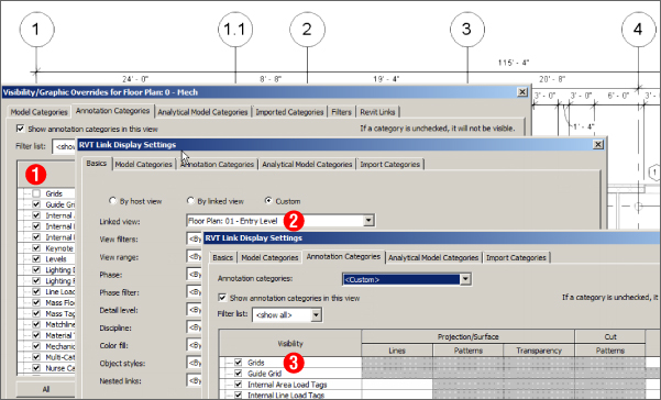
Figure 4.13 Example of linked file view settings showing the Grids category turned off in the host view (1) and By Linked View selected for the Architectural link (2 and 3)
It is not likely that your consultants will have set all their views in a manner that matches your preferences for seeing the link, so you also have the Custom option for visibility. Selecting Custom activates all the setting options on the Basics tab of the RVT Link Display Settings dialog box. With this option, not only can you choose a linked view, but you can also determine other behaviors for the display of the link. You do not have to choose a linked view if you want to control the visibility of only certain components. The Custom option is the same as accessing the Visibility/Graphic Overrides dialog box, but for the link only. Once you have selected Custom, you can use the other tabs in the dialog box to set the visibility of the components within the link. When you select a tab, the items are grayed out. You must set that specific category to Custom as well by using the pull-down at the top of the tab, as shown in Figure 4.14.
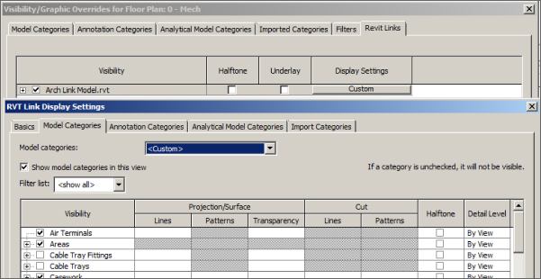
Figure 4.14 Setting a model category within a linked file to Custom
After setting a category to Custom, you can control the visibility of any Revit model category within the linked file. You can control elements in the Model categories as well as the Annotation categories and any Import items such as linked CAD files. Figure 4.15 (top) shows that the Grids category is displayed because the linked structural file is set to display by a linked view, even though the Grids category is turned off for the host view. A better solution might be to set the structural link to a Custom display and turn off all Annotation categories except for Grids, as shown in Figure 4.15 (bottom). Doing this will automatically keep the architectural link as a halftone and will display only the items you want to see in your view.
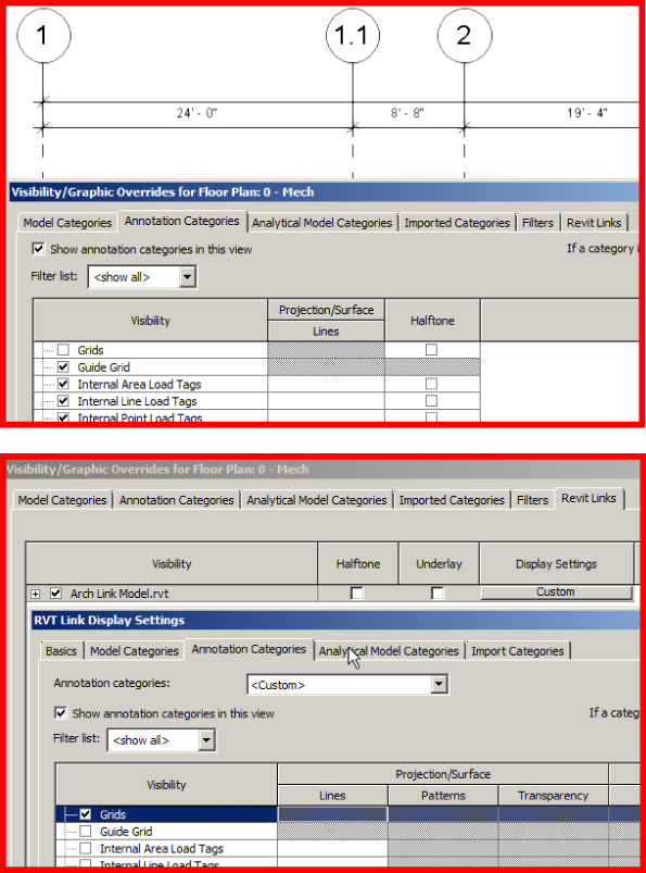
Figure 4.15 Grids turned off in the view (top); the Architectural link set to Custom and displaying only the Grids category (bottom)
In this example, the Custom option allows for the display of grids without displaying other architectural annotations, such as dimensions.
You can also control the visibility of worksets within a linked Revit file. If you choose not to make your worksets visible in all views within your project, your consultants will have to turn on the visibility of the workset when your file is linked into their project file. The visibility of a workset can be turned on or off by accessing the linked Revit file in the Visibility/Graphic Overrides dialog box. Clicking the button in the Display Settings column for the linked file opens the RVT Link Display Settings dialog box. This dialog box has a tab for controlling the visibility of worksets, as shown in Figure 4.16. Setting the display to Custom allows you to turn on or off the visibility of any worksets within the linked file.
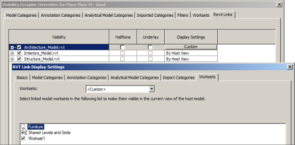
Figure 4.16 Visibility control of worksets within a linked file
The output of Revit documents can vary depending on the type of printer you use. The most common issue is that the automatically halftone-linked files do not print darkly enough. Revit enables you to control how dark the linked files appear and print. You can find the Halftone/Underlay settings on the Additional Settings menu located on the Manage tab, as shown in Figure 4.17.
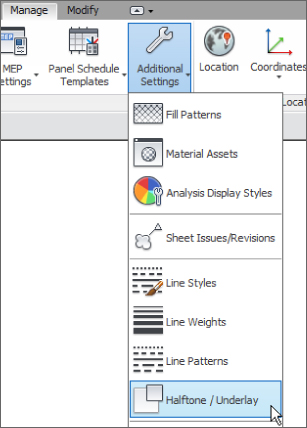
Figure 4.17 Halftone/Underlay settings
In the Halftone/Underlay dialog box, you can turn off the automatic halftone of linked architectural and structural files by deselecting the Apply Halftone check box. You can also override the line weight of a background Revit link. If you are using an underlay in your view, you can change the line pattern to any of the patterns you have loaded in your project. Figure 4.18 shows the Halftone/Underlay dialog box with sample settings applied.
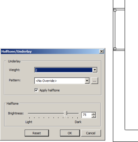
Figure 4.18 Halftone/Underlay sample settings applied
The Brightness slider on the bottom half of the dialog box lets you manually adjust the percentage of halftone applied to all halftone items in the view, both linked items and those in your model. Notice that only the elements within the link that are halftone are affected. The plumbing fixtures are part of the linked architectural model, but because they are not an architectural or structural category, they are not affected by the adjustment. The settings that you use apply to the entire project, so you need to set them only once. This is a helpful tool for getting your documents to print properly.
Coordinating Elements within Shared Models
One of the key benefits of using a BIM solution such as Revit MEP is that you can see changes in the design more readily, because you see more of the other disciplines' work than you would in a traditional workflow. The ease of cutting section views and inspecting the model in 3D allows you to notice what is going on, not only with your design but also with the project as a whole. You may not have time to look over the model inch by inch, though, so there are some items that you can monitor to see whether the design changes in a way that affects your systems.
Monitoring Elements
Revit gives you the capability to monitor certain elements within a linked file in order to be made aware of any changes. This functionality is limited to a few categories because, after all, you wouldn't want to know every time the architect moved a chair or changed the color of a door. The types of components that can be monitored are items that, if changed, could have a major effect on your design, especially late in the game. The architectural categories that can be monitored for coordination are Levels, Grids, Columns, Walls, and Floors. These items are often hosts for components in your model, so being aware of changes to them provides you with a higher level of coordination.
The Copy/Monitor function in Revit not only lets you monitor an element of a linked file but also allows you to create a copy of that element within your file. The use of face-hosted elements eliminates the need to copy items just so that you can have something as a host. There are items, however, that are important to coordinate, such as levels and grids.
Your template file may contain levels in order to have preset views, but your levels will not likely be the same on every project. After pinning a linked file in place, the next thing you should get into the habit of doing is monitoring the levels. This mainly applies to the architectural link, because architects are the ones who will determine floor-to-floor heights. If your file has fewer levels than the linked file, you can copy the additional levels, and they will then be monitored automatically.
To coordinate with the levels in the linked file, follow these steps:
- Open an elevation or section view of the model to see the level locations.
- Align your levels to the levels in the linked file.
- Set your levels to monitor the levels in the link by clicking the Copy/Monitor button on the Collaborate tab. Your two options for monitoring are selecting items in your file and selecting a link.
- Click the Select Link option, and click the link in your view. The Ribbon changes to display tools for Copy/Monitor.
- There is no need to copy levels that already exist in your file, but you will want to modify them to match the name and elevation of the levels in the linked file before actually starting the monitor process.
If you are prompted to rename corresponding views when changing a level's name, it is best to choose not to. Otherwise, the names of your views may not be correct according to your standards. If you do not change the level names, then your levels will monitor the linked levels relative to their location. Figure 4.19 shows an example of project levels and linked file levels.

Figure 4.19 Project levels and linked file levels
- Click the Monitor button on the Tools panel, and select the level you want to coordinate with the linked level.
- Select the linked level that you want to monitor.
- Repeat steps 5 and 6 for each level that you have in your file. If there is a level in the link that does not exist in your file, you can use the Copy button to create a monitored copy of the level.
It is not necessary to monitor all levels because your consultant's file may contain levels for use as coordination points rather than for view creation. Only monitor levels for which you need to create views or to which you need to associate your model components, as shown in Figure 4.20.
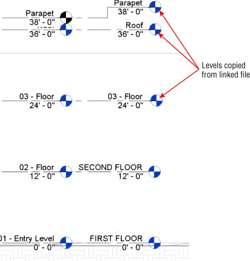
Figure 4.20 Using Copy/Monitor for levels
When you use the Copy button in the Copy/Monitor function, the copied element will automatically monitor the object from which it was copied, so there is no need to repeat the monitor process after copying an item.
- After you have finished coordinating your levels to the levels within the linked file, click the Finish button on the Copy/Monitor tab. You can now create views for any additional levels you may have added.
You also have the ability to copy/monitor certain MEP elements within a linked file. Clicking the Coordination Settings button on the Coordinate panel of the Collaborate tab opens the dialog box for establishing how MEP elements will be copied from a linked file into your project. Figure 4.21 shows the dialog box. These settings are specific to the current project.
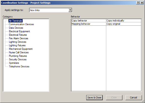
Figure 4.21 Coordination Settings dialog box
You can apply the settings to any of the linked files within your project by using the drop-down at the top of the dialog box, shown in Figure 4.22.
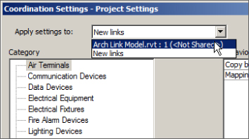
Figure 4.22 Apply Copy/Monitor settings
There are three choices for the Copy Behavior setting of each category, as shown in Figure 4.23. Items can be batch copied, which will allow for multiple elements of the category to be copied. Items can be copied individually, or you can choose to ignore a category.
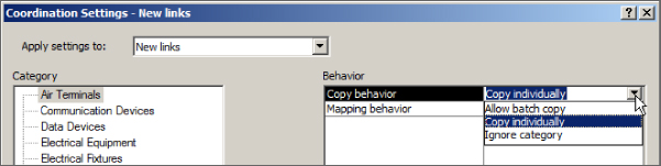
Figure 4.23 Copy/Monitor behavior settings
If you are applying settings for new links, the Mapping Behavior setting, shown in Figure 4.24, is set to copy the original components by default. If you have selected a specific linked file, you can set the mapping behavior for a category as long as the category is not set to be ignored.
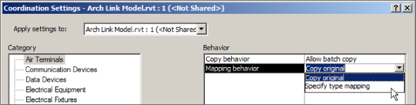
Figure 4.24 Copy/Monitor mapping options
When you choose the Specify Type Mapping option, the Type Mapping settings appear beneath the category in the list at the left of the dialog box. When you click the Type Mapping option below the category, the dialog box changes to show the items in that category that are in the linked file and a column for defining what family within your project to use, as shown in Figure 4.25. Be sure to map to a family that has the same insertion point and hosting option. Families with different insertion points will cause undesired results when mapped. You cannot map a ceiling-hosted family to a face-hosted family.
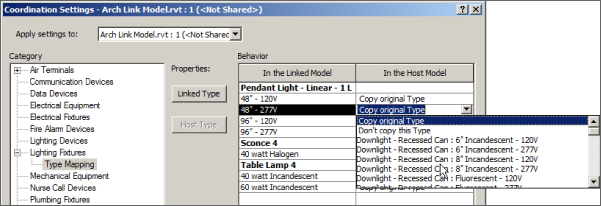
Figure 4.25 Type mapping options
The Linked Type and Host Type buttons allow you to view the Type Properties dialog box for the selected families. You cannot make changes to the properties, but you can see them in order to determine the right families to use, as shown in Figure 4.26.
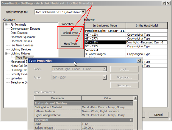
Figure 4.26 Type properties shown in the Coordination Settings dialog box
The main purpose for monitoring items is to be alerted when a change has been made to them. This is done by the Coordination Review feature within Revit. When you update your linked files, if there is a change to an item that you are monitoring, a warning will appear during the loading of the link, as shown in Figure 4.27. This warning lets you know that a Coordination Review needs to be executed. You can ignore this message, but just because you can, should you? Who will do the coordination review? This should be part of one team member's role in the project.
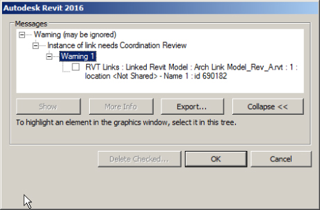
Figure 4.27 Coordination Review warning
Responding to Change Alerts
To perform a coordination review, you can click the Coordination Review button on the Collaborate tab. The command is also on the Modify | RVT Links tab that appears when you select a link that has monitored elements in the view window. The dialog box that appears contains a list of the issues that require coordination, as shown in Figure 4.28. Expanding each issue will reveal the specific elements involved.
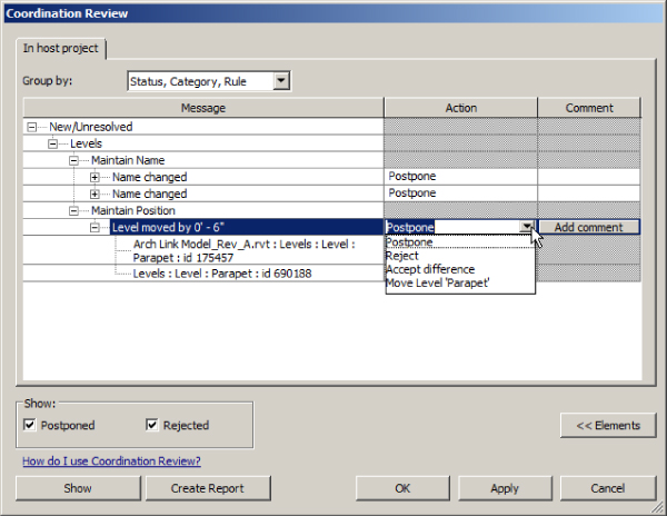
Figure 4.28 Coordination Review dialog box
The Action column provides four options for dealing with the coordination issue:
- Postpone If you choose to postpone the action, Revit will warn you of the issue each time your file is opened or the linked file is reloaded, until another action is taken.
- Reject This option should be accompanied by a description in the Comment column to the right. If a change has been made that you must reject because of design constraints or for some other reason, you can select this option. When you send your file to your consultants, they will receive a notice that a coordination review is required and will see that you rejected the change. Most likely, a change that is rejected will generate communication between team members, but adding a comment is a good way to document the action choice. Comments will be visible to other team members only when the Create Report feature is used.
- Accept Difference This choice can be used when the change does not affect your design and when the effort to coordinate outweighs the benefit. For example, you may be monitoring a wall in the architectural model to see whether it moves. On the day the project is due, you receive an alert that the wall has moved 1⁄32″. You could decide that the change is insignificant enough to allow for the difference.
- Modify Your Element To Match The Item It Is Monitoring In Figure 4.29, you can see the result of using the Move Level option (shown earlier in Figure 4.28) so that the level is coordinated with the linked Revit model. When this option is chosen, the change is made automatically by Revit. Select the option, and click the Apply button to see the change occur. If you are not in a view that shows the items requiring coordination, you can select one of the items in the list and click the Show button in the lower-left corner. Revit will search for a view that shows the selected item and open that view.
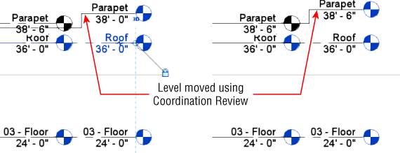
Figure 4.29 Level adjusted by coordination review
If the change made has too great an effect on your model, you can simply undo the action and revisit the Coordination Review dialog box to select another action.
Reconciling Hosting
Face-hosted families allow you to attach your components to the 3D faces within a linked file. When the host of one of these types of families is deleted, the family will remain in the model, but it loses its host—it will no longer be associated with the linked file. This behavior can cause objects within your model to be floating in space when they should be attached to a surface. A common reason for an element losing its host is that the host was deleted and redrawn elsewhere instead of just being moved. For example, if you have some air terminals hosted by the face of a ceiling and the ceiling needs to move up, the architect may delete the ceiling and create a new one at the new elevation. This would cause your air terminals to be floating below the new ceiling.
Reconcile Hosting allows you to identify and deal with any families that have lost their host. Click the Reconcile Hosting button on the Coordinate panel of the Collaborate tab to access the Reconcile Hosting palette, shown in Figure 4.30.
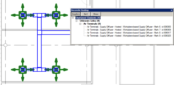
Figure 4.30 Reconcile Hosting palette
You can dock this palette to the interface, have it float, or share the Properties palette/Project Browser window as a tab. When the palette is active, any objects that are listed will be green in the model view. You can click the Graphics button on the palette to change the visual display of orphaned elements when the palette is active.
The Show button allows you to locate an item selected from the list if it is not readily visible in the current view. The Sort button lets you sort the list either by the linked file and then the categories or by the categories and then the linked file.
You can right-click an item listed in the palette and choose the option to delete it or choose the Pick Host option, which allows you to place the element on a new host. However, if you pin the elements in place first, you can pick a new host without altering their actual position.
Maintaining Project Coordination
Proper setup of your project file is essential for maintaining coordination throughout the life of the project. You can find an example of how to do this on this book's web page at www.sybex.com/go/masteringrevitmep2016. Create a project file by following these steps:
- Open the
RMEP2016_Ch04_Dataset.rvtfile, which can be downloaded from this book's web page. (Also download theRMEP2016_Sample_Architecture.rvtfile.) - Open the MH - Level 1 floor plan view and click the Link Revit button on the Insert tab.
- Select the
RMEP2016_Sample_Architecture.rvtfile, and choose the Auto – Origin To Origin positioning option. Click Open. - Select the linked model in the active view window, and click the Pin button on the Modify | RVT Links tab.
- Open the North elevation view.
- Use the Align tool to align the Roof level in your model to the ROOF level in the architects file.
- Click the Copy/Monitor button on the Collaborate tab. Click Select Link.
- Click the linked model in the view window.
- Click the Monitor button on the Copy/Monitor tab.
- Click the First Floor level at the right, and then select the First Floor level of the linked model.
- Repeat step 9 for the Roof level.
- Use the Copy option for the floor levels Second Floor and Raised Second Floor.
- Click the Finish button on the Copy/Monitor tab.
Working with Files from Other Applications
Revit files are not the only type of files that you can link into your project. The Revit platform is compatible with many types of CAD formats as well. As you move into using a BIM solution for your projects, try to use CAD files as little as possible. A large number of linked CAD files in your project can cause the project file to perform poorly. Choose the files that will save you time overall on the project. The following CAD file formats can be linked into Revit:
- DWG
- DXF
- DGN
- ACIS SAT
- SketchUp
You can also insert image files and link Design Web Format (DWF) markups. There are two options for bringing non-Revit file types into your project: you can link them or import them. Linking is the preferred method, because a linked file will update as the file changes without you having to repeat the process of inserting the link. Linked CAD files will show up in the Manage Links dialog box with options for the pathing of files, reloading, and unloading. If you share your project that contains CAD links with a consultant and you do not give the consultant the CAD files, Revit will display the CAD link as it last appeared in your file.
Linking CAD Files
Because there is no Revit version for civil engineering, it is likely that you will receive the files from your civil engineering consultant in some type of CAD format. The process for linking these types of files is similar to linking a Revit file:
- On the Insert tab, click the Link CAD button. The dialog box for linking a CAD file, shown in Figure 4.31, contains more options than the one for linking a Revit file.
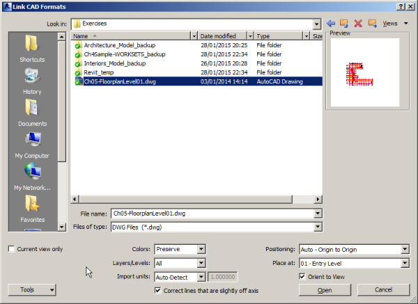
Figure 4.31 Link CAD Formats dialog box
The check box in the lower-left corner provides the option for linking the file to the current view only. This will keep you from having to turn off the CAD link in any other view.
The Colors drop-down list, shown in Figure 4.32, allows you to invert the colors of the CAD file, preserve them as they exist, or turn all the linework to black and white.
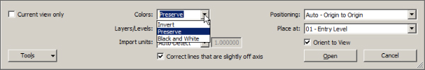
Figure 4.32 Color options for a linked CAD file
- Determine which layers of the CAD file you want to load. This is similar to loading specific worksets of a linked Revit file. You can load all the layers within the file, you can load only those that are visible within the drawing (layers that are on and thawed), or you can specify which layers you would like to load, as shown in Figure 4.33.

Figure 4.33 Layer options for a linked CAD file
Choosing the Specify option will open a dialog box from which you can select the desired layers within the CAD file to load.
You can remove layers within the linked CAD file after the file is in your project by clicking the link in the view window and clicking the Delete Layers button in the Import Instance panel.
- Define the units for the file to be linked in. The Auto-Detect option, shown in Figure 4.34, causes Revit to use the unit setting that the CAD file is using. This can lead to inaccuracy if the units in the CAD file are not defined. The units can be modified in the properties of the linked CAD file after it is placed into the project.
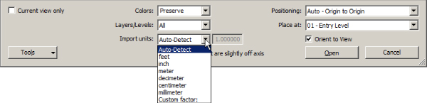
Figure 4.34 Import Units options for a linked CAD file
- Position the CAD file. The positioning options for a linked CAD file are the same as for a linked Revit file. If you are using shared coordinates for your project, these coordinates need to be communicated to the civil engineering consultant in order for the site plan to align properly. If not, you can place the CAD file manually to line up the graphics.
Typically, the architect will provide a building outline to the civil engineering consultant that will appear in the linked site plan and will handle the establishment of shared coordinates. Whatever method is chosen, be sure to pin the link in place to prevent accidental movement. The Orient To View check box in the lower-right corner will position the file appropriately based on your view orientation, either Plan North or True North. When creating sections or elevations in CAD, you are often doing so in the plan orientation of the file. Revit will rotate the plan of the CAD file into alignment in a section or elevation view if this option is selected. If only the current view is chosen, then this option is On by default.
If you choose to use the Import option instead of linking, the options for placing the file are the same except for the automatic orientation to your view. For the sake of good file hygiene, it is best to link CAD files instead of importing them, especially if you are bringing in the file only for temporary use.
The Correct Lines That Are Slightly Off Axis option helps reduce that pesky warning that informs you that a line is not completely straight by altering it automatically. This may not be a wise choice when linking a site plan due to the nature of the linework representing grading and other site features.
You can link any other type of CAD file needed in your project, such as files that contain details or diagrams. These types of drawings can be linked to a drafting view that can be placed on a sheet, or they can be linked directly onto a sheet. To remove a linked CAD file, you can simply select it in the view window and press the Delete key. This will remove it from the project completely.
You can view the properties of elements within a linked CAD file by selecting the link and clicking the Query button in the Import Instance panel that appears when the link is selected. When you click this, each element within the linked file can be selected, as shown in Figure 4.35.
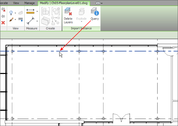
Figure 4.35 Selected item within a linked CAD file
Clicking an item will open the Import Instance Query dialog box, shown in Figure 4.36, with information about the selected item. The Delete and Hide In View buttons in this dialog box apply to the entire category of the selected item.
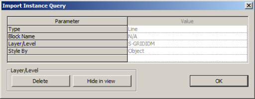
Figure 4.36 Import Instance Query dialog box
You can control the visibility of items in the linked CAD file from the Visibility/Graphic Overrides dialog box. Its Imported Categories tab contains a list of all linked and imported CAD graphics. The layers within the linked files are listed and can be turned on or off, and their color, line weight, and line pattern can be overridden.
Exporting Your Revit File to a CAD Format
Sharing your project file with consultants who are not using Revit is as important as receiving their files. You can export your file to various CAD formats to be used by your consultants. The most important task is to establish the translation of model elements to CAD layers or levels. This is set up in the export options accessed by choosing Export ⇨Options from the application menu (see Figure 4.37).
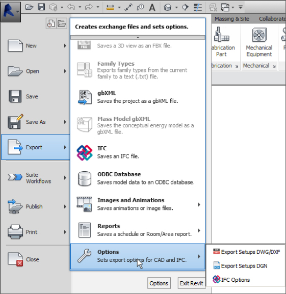
Figure 4.37 Export options
When you select one of the file format export settings, the dialog box that appears contains a list of all the Revit model categories and their subcategories. You can assign a CAD layer or level and a color to each category and subcategory depending on whether the elements are displayed as cut or in projection. Figure 4.38 shows an example.
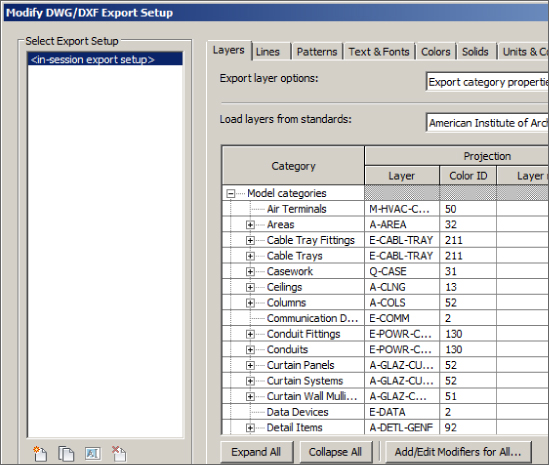
Figure 4.38 Layer export settings
Once you have provided a layer and color for the elements that you need to translate to CAD along with setting the other export options, you can save the settings for future use. See Chapter 25, “Creating a Project Template,” for more information on establishing export settings.
With your export settings established, choose the appropriate CAD format from the Export tool on the Application menu. The Export CAD Formats dialog box provides you with options for selecting multiple sheets or views to export and the properties of the exported files.
Click the Next button after you have chosen the views or sheets you want to export and a dialog box appears that will let you browse to the file export location. At this point, you can determine the software version to use for the export. If you are exporting a sheet view, you have the option to turn each view on the sheet into an external reference. If you are exporting a model view, selecting this option will cause any linked files in the view to be exported as separate CAD files to be used as external references. This option is the default if you choose the Manual option for file naming.
Figure 4.39 shows the resulting files from an export of a sheet that contains one model view and a schedule. The highlighted file is the complete sheet. The other files are external references that make up the sheet. The titleblock is a block entity in the DWG, and the schedule is linework and text in the sheet file.
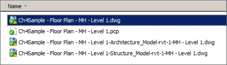
Figure 4.39 Files created from a Revit export
Notice also that the logo in the titleblock was exported as an image file and an AutoCAD plotter configuration file (.PCP) file was created. This allows anyone you are sharing your files with to print them the same way you would.
Linking IFC Files
The process for bringing in Industry Foundation Classes (IFC) files changed in the 2015 release of Revit MEP. In the past you would open the IFC file and then save it as a Revit file in order to link it into your project. The Link IFC button was also added to the Link panel of the Insert tab, and it allows you to bring in an IFC file without having to open the file.
When you click the Link IFC button, the dialog box that appears allows you to browse to the file location. The file types that can be linked are shown in Figure 4.40.
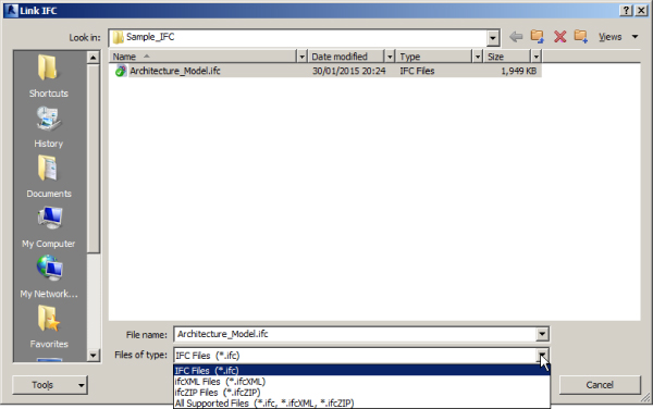
Figure 4.40 Link IFC dialog box
Once you select a file and click Open, Revit will read the file, convert it to a Revit file, and link it into your project all in one step. The Revit file that it creates is saved in the same location as your project file. The link to the IFC file can be managed via the Manage Links dialog box, as shown in Figure 4.41.
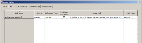
Figure 4.41 IFC file in the Manage Links dialog box
The file will be a part of the workset that is currently active when the file is linked in, and the visibility of the linked file can be managed the same way as any other linked Revit file.
When the IFC file is updated, the Revit file created by clicking the Link IFC button is updated; however, you need to use the Reload From option on the IFC tab of the Manage Links dialog box to update the link within your project. You cannot simply reload the linked Revit file.
New to Revit MEP 2016 is the ability for IFC files to support the following functionality:
- Room bounding—click on Edit Type in the Properties palette and the elements in a linked IFC can become room-bounding elements in the same way as a linked Revit file.
- Dimensions
- Snapping
- Alignment
- Host face based families
Using Image Files in a Revit Project
Image files may be necessary for your Revit project to convey design information. They can also be used for presentation documents to add a more realistic look to the model and for logos on sheet borders. Sometimes, renovation projects require information from older documents that are not in Revit or a CAD format. You can save the time required to re-create this information by inserting scanned images of the documents. As with linking CAD files, be careful not to use too many images in your project for the sake of model performance.
You can insert an image file directly into any type of view except for 3D views (unless you are placing a decal). Click the Image button on the Insert tab, and browse to the location of the image. Images are imported into your project, not linked, and they will travel within the file when shared. Figure 4.42 shows placing an image into a sheet border. An outline of the image appears at your cursor for placement.
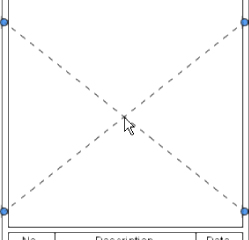
Figure 4.42 Placing an image into a view
Once the image has been placed, you can resize it by clicking and dragging the grips at the corners of the image. The aspect ratio of the image is maintained when dragging a corner point. To access these grips after placement, just click the image. You can also use the Scale tool to resize an image to be close to a specific dimension, assuming you know the length of something in the image. You can place text and linework on top of the image as necessary.
If you need to show an image in a 3D view for rendering (like signage perhaps), you can bring the image into your file by creating a decal. The Decal button is located on the Insert tab. Clicking the bottom half of this button allows you to place a loaded decal or access the Decal Types dialog box, shown in Figure 4.43. You will first need to create a decal type within your project by clicking the Create New Decal icon in the lower-left corner.
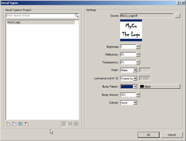
Figure 4.43 Decal Types dialog box
After naming your decal type, you can browse to the location of an image you want to use. If the image location changes, the decal will no longer display the image in the model. You will have to choose a new path for the decal type. This means that if you share your file with an owner or consultant, you need to also share any image files that are included.
The dialog box offers other settings for the rendering appearance of the image. Once the decal type is created, you can use the Place Decal option on the Decal button to insert the image into a 3D view. Settings for the decal size appear on the Options Bar during placement. You can place the decal on any one-directional planar 3D face, such as a wall, curved or straight. It will appear in the view as a box that defines the size of the image, as shown in Figure 4.44.
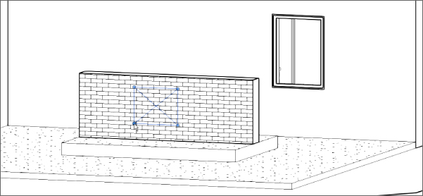
Figure 4.44 Placing a decal in a 3D view
The decal will display its associated image only in rendered views. This allows you to show things such as signs or logos without having to model them. Figure 4.45 shows an example. Valid image file types for decals are BMP, JPG, JPEG, PNG, and TIF.
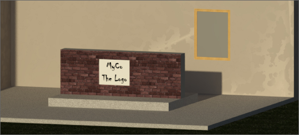
Figure 4.45 Decal shown in a rendered view
Image files brought into your project will not appear in the Manage Links dialog box. You can use the Manage Images button on the Insert tab to see what images are used in your project. Decals will not appear in the Manage Images list. The Decal Types button also appears on the Manage Project panel of the Manage tab.
If you are working with a client or consultant who is not using Revit, you can still share your model by using the DWF export capabilities within Revit. You can export your model in either 2D or 3D format depending on your client's needs. DWF files are similar to PDF files in that they are meant to be viewed and commented on. The graphics and model geometry cannot be edited in a way that modifies the actual design model, but they contain more than just graphical information. This will help you include your clients or consultants in the BIM process of your project by providing them with the I in BIM—information.
To create a DWF file for sharing, choose the Export tool from the application menu. There you will see the DWF/DWFx option (see Figure 4.46).
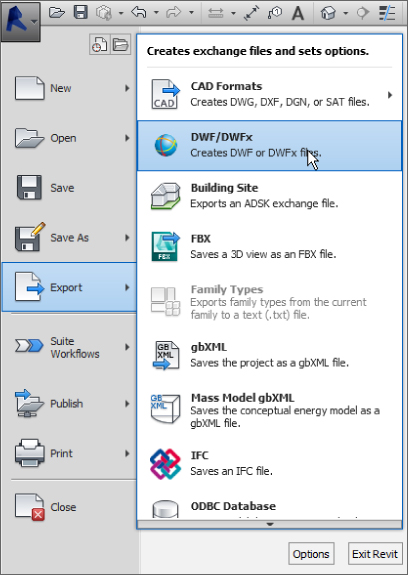
Figure 4.46 DWF/DWFx Export tool
In the DWF Export Settings dialog box, you will see a preview of the current view and options for the output. If you want to create a 3D DWF, you need to have a 3D view open in the drawing area when you select the Export function. If your view discipline is set to Coordination, only the elements within your file will be exported; linked files will not be included in the DWF.
Setting Options for Quality Control
The topics in this chapter address how you can work with all the files in your project to better coordinate your design with your consultants. One of the best things you can do is to make sure that the file you are sharing is as complete and accurate as possible.
You can use some of the core functionality of Revit MEP to set up a system for quality control and project review. During visual inspection of the project, you may notice issues that require coordination. Unless you are the person responsible for modeling, there needs to be a workflow in place to document and manage the issues.
Consider creating an annotation family that acts as a comment tag for whoever may be reviewing the project. This tag can contain as little or as much information as you want. The sample shown in Figure 4.47 has parameters to assign a number, date, status, and owner of a comment along with space for a brief description. The project reviewer can place these tags throughout the project to point out areas that require modification or coordination. Comments can be made regarding issues within your file or issues about your consultant's files. When you share your file, your consultant can view the comments without the need for you to send additional information or files.
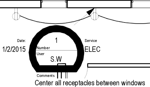
Figure 4.47 Sample review comment tag
These tags can be scheduled, and the schedule can be used as a means of tracking the comments. The schedule also allows users to easily locate the comment tags by using the Highlight In Model button on the Element panel of the contextual tab that appears on the Ribbon. Figure 4.48 shows a sample schedule of a review comment tag used in a project.
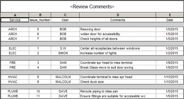
Figure 4.48 Sample review comment schedule
As comments are addressed by users, the tags can be deleted from the views. An empty schedule would indicate that all comments have been addressed. Another option would be to add a parameter, such as a check box, to the comment tag to indicate when a comment has been addressed. Using this workflow can be an efficient and productive method for dealing with coordination issues during the design process.
Another option to consider for quality control is using DWF markups in lieu of the traditional “red line on paper” method. The benefit of using DWFs is not only in the reduction of printing but also that your markups, and how they are handled, can be documented and archived. You can generate a DWF file of multiple sheets, which can be digitally marked up using the free Autodesk Design Review software that can be installed with Revit or is available for download from www.autodesk.com. The marked-up DWF sheets can then be brought into Revit and overlaid on their corresponding sheet views by using the DWF Markup command on the Insert tab, as shown in Figure 4.49.
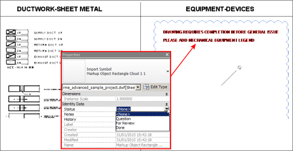
Figure 4.49 Revit sheet with DWF markup
As changes are made to your Revit file, you can edit the properties of the marks from the DWF, categorizing them as complete. The Revit file can then be exported to DWF again, and the new DWF file will show the marks as complete by highlighting them in yellow. The username and time of completion of the mark are also stored in the DWF file. This workflow enables you to keep track of who made changes and when those changes were made.
Using Cloud-based Solutions
When working in an environment where not all involved parties are in the same location, using a cloud-based solution is an effective way to achieve coordination and collaboration.
Depending on what solution you use, a cloud-based project may allow access to project files in real time. This eliminates the need to wait for files to be uploaded or shared and ensures that all parties are using the same files. Users can access the files from anywhere with an Internet connection. Many cloud solutions offer mobile applications for field use. This means you do not need to have an installation of the software being used in order to work on the project files. All of these attributes further enhance a design and construction team's ability to coordinate efficiently.
There are many considerations for choosing a cloud-based solution for your projects. What type of hardware is required to run BIM software such as Revit MEP effectively? Will the hardware be internal to your network, allowing access from outside users, or will it be hosted by some third-party provider? What are the security risks? How is software licensing handled? Cloud computing is becoming popular in business and technology, and BIM projects can benefit greatly from it.
The Bottom Line
- Prepare your project file for sharing with consultants. Taking care to provide a clean, accurate model will aid in achieving an integrated project delivery.
- Master It Describe the importance of making worksets visible in all views when your file will be shared with consultants.
- Work with linked Revit files. There are many advantages to using linked Revit files in your project. Revit provides many options for the visibility of consultants' files, allowing you to easily coordinate your design.
- Master It How would you turn off a model category within a Revit link while allowing that category to remain visible in your model?
- Coordinate elements within shared models. Revit can alert you to changes to certain model elements within linked files. Managing these changes when they occur can reduce errors and omissions later in the project and help keep the design team coordinated.
- Master It MEP components within a linked file can be copied and/or monitored. True or false: You must have the same family loaded into your file in order to monitor it from a linked file.
- Work with files from other applications. Not all of your consultants may use Revit. This does not mean that you cannot use their files to develop and coordinate your design. You can also share your design by exporting your file to a format they can use.
- Master It Describe the difference between linking and importing a CAD file and why the linking option is preferred.
- Set up a system for quality control. As a BIM solution, Revit provides functionality to keep your design coordinated with your consultants.
- Master It What functionality exists in Revit that could allow a design reviewer to comment on coordination issues within a project?