
Chapter 14
Circuiting and Panels
You put information into the components that you use to build your Autodesk® Revit® MEP 2016 models so you can use that data to confirm the integrity of your design and improve coordination. The computable data in a model is dependent on the systems that you establish. Revit MEP recognizes many types of systems, from airflow and piping to electrical systems where circuits are the systems you create to establish the relationship between a fixture or device and its associated equipment. This relationship is typically conveyed on construction documents by schematic lines representing the wiring. There are multiple circuit types that can be created: power, data, telephone, communications, security, fire alarms, nurse call systems, and controls.
With the parametric and connective nature of model components, you have the ability to maintain the relationship between your model elements and the schematic wiring associated with them. Wires can be used to display information with tags and extract, or offer, data in schedules. Even if you do not choose to show wiring on your construction documents, you can still take full advantage of the Revit process by creating and managing electrical circuits.
The electrical settings established for your projects are the backbone of creating circuits and wiring. When correctly set up in your project template, they can make creating and managing circuits easy and efficient.
In this chapter, you will learn to do the following:
- Establish settings for circuits and wiring
- Create circuits and wiring for devices and fixtures
- Manage circuits and panels
- Use schedules for sharing circuit information
Establishing Electrical Settings
The electrical settings for your project determine your ability to connect devices and equipment and also define how wiring and electrical information is displayed. You can define the types of voltages available and also the distribution system characteristics. This allows you to connect devices properly and prevents you from accidentally wiring objects to the wrong panel. You can set the visibility behavior of tick marks to show wire counts and how wire tags display the electrical information. All of these settings are project specific, so you can create a standard setup in your project template based on company or project-type requirements.
You can access the electrical settings at any time by using the keyboard shortcut ES, clicking the MEP Settings button on the Manage tab, or using the screen shortcut from the Electrical panel of the Systems tab as shown in Figure 14.1.
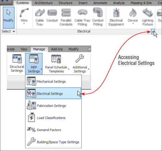
Figure 14.1 Accessing electrical settings
The Hidden Line settings in the Electrical Settings dialog box allow you to establish the size of the gap that is shown when a conduit and cable tray cross over each other or another MEP object. The gap size is relative to the scale of the views. You can choose how hidden lines display in your view in several ways:
- Set the view to any MEP discipline. In these discipline-specific views, hidden lines are displayed by default.
- When the discipline of the view is set to Coordination, change the Show Hidden Lines parameter to All.
Hidden lines cannot be displayed in Wireframe mode.
Figure 14.2 indicates how this works in practice; when Show Hidden Lines is set to By Discipline and the Discipline is set to Electrical (1), hidden lines are not displayed when the view is set to Wireframe. In a Coordination view (2), hidden lines will be displayed for all disciplines when Show Hidden Lines is set to All.
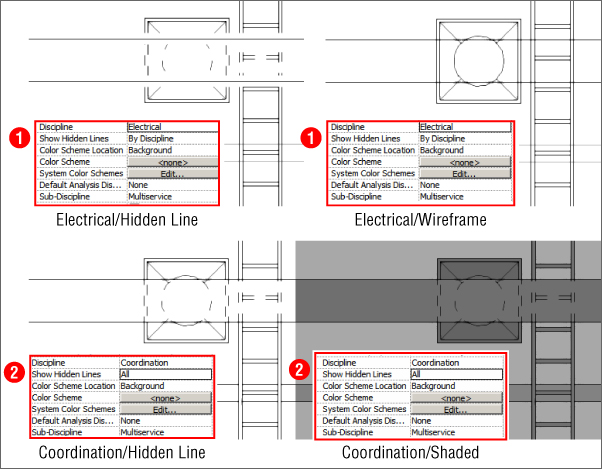
Figure 14.2 Hidden Line options
The General settings determine how the electrical data is displayed for devices and the format for describing the electrical characteristics. These settings do not affect the behavior of electrical devices or circuits; they affect only how information is displayed in the Electrical Data parameter of devices. There are also settings for circuit naming if you name your circuits by phase.
This section is also where you can define how load names are capitalized in panel schedules. You can choose from the preset options provided. Changing these settings after panel schedules have been generated does not affect the existing load names in a schedule. See Figure 14.3 for the various options available.
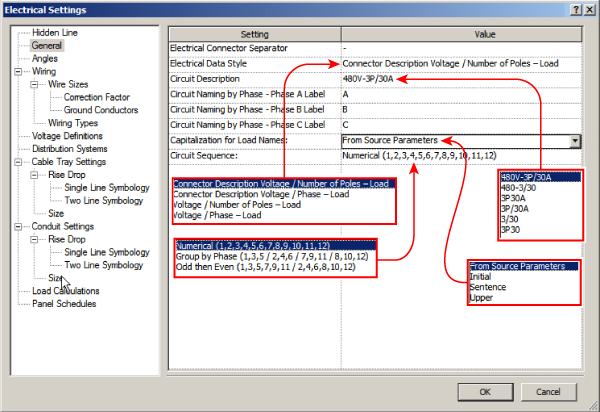
Figure 14.3 Electrical Settings, General section
Wiring Settings
In the Wiring settings section of the Electrical Settings dialog box, you can define the ambient temperature to be used in order to apply a correction factor to the load of a circuit. The default setting is 86°F (30°C), which applies a correction factor of 1 for any of the three wire temperature ratings. In this section, you can also define the size of the gap that is displayed when wires cross. The value you input into this setting indicates the print size of the gap on a full-size print.
Tick marks for wiring are also defined in the Wiring section of the Electrical Settings dialog box. You can create an annotation family to use as a tick mark if the defaults do not comply with your standards. The family must be loaded into your project in order for it to be assigned to represent hot, neutral, or ground wires. You can choose to show a slanted line across the tick marks to represent the ground conductor no matter what families you use. There are three options for displaying tick marks, as shown in Figure 14.4. Changing the display setting for tick marks affects all wires in your project.
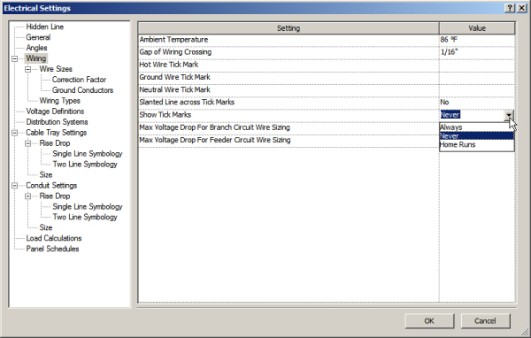
Figure 14.4 Wiring section of Electrical Settings dialog box
The three tick mark settings are as follows:
- Always With this setting, tick marks are displayed on any wire when it is drawn.
- Never With this setting, tick marks are not displayed on any wire when it is drawn.
- Home Runs With this setting, tick marks are displayed only on wiring home runs and not on wires between devices on the same circuit.
In this section, you can also define the maximum voltage drop percentage for branch circuits and feeders.
The Wire Sizes section of the Electrical Settings dialog box allows you to define the sizes of wires you want to use for different circuit ampacities. You can set the wire sizes for aluminum and copper wire. You can even create a different wire material, temperature rating, or insulation type if your project requires it. You can vary the wire sizes for the three standard wire-temperature ratings and for different types of insulation. This gives you the ability to control the types of wires used for different circuits because you can remove ampacity ratings for different wire temperature and insulation combinations.
The Used By Sizing column allows you to establish which wire sizes are available to be used when the wire size of a circuit is calculated. You can assign only one wire size per ampacity, so if, for example, you want to use #12 wire for 15-amp and 20-amp circuits, you would have to delete the 15 A ampacity and set the size for the 20 A ampacity to #12 wire. This does not mean you cannot use a 15-amp circuit in your project. The smallest wire size available in your list is for an ampacity smaller than the smallest in your list. Figure 14.5 shows an example of wire sizes for a project. Any circuits smaller than 20 amps in the project have to use #12 wire.
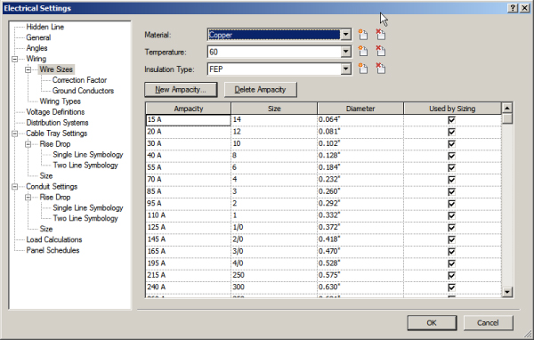
Figure 14.5 Wire Size settings
Use the Correction Factor section of the Electrical Settings dialog box to set a correction factor based on temperature to be used in load calculations. You can set correction factors for different wire temperature ratings and materials. The Ground Conductors section allows you to set the equipment grounding conductor size for different ampacities of different wire materials. So, you have the ability to control several factors that determine the wire sizes that are calculated for your circuits.
In the Wiring Types section of the Electrical Settings dialog box, you can create different types of wires for different uses. By creating different wire types, you have the ability to assign all the desired settings to a type, and as with component families, you can switch between wire types in the model. Creating wire types also provides you with an easy way to control the visibility of certain wires by using a view filter. You can give your wire types unique names that define their use or some characteristic about them.
You can set the material, temperature rating, and insulation used by a wire type. You can also set the maximum wire size for a type. If a circuit requires a larger wire size than the maximum, parallel sets of wires that do not exceed the maximum size are automatically created to accommodate the load. You can establish whether your wire type requires a neutral conductor and, if so, set the neutral size equal to the hot conductor size or set it as an unbalanced circuit. After the neutral conductor is sized, the value you enter for the neutral multiplier is assigned.
Although there are conduit tools for modeling, there is no connection between the conduit or cable tray and circuits yet. It is necessary to use these settings to establish the conduit material for your wire type so that these can be passed through the system and used for voltage drop calculations. Figure 14.6 shows some examples of wire types created for a project.
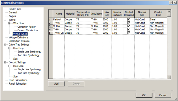
Figure 14.6 Wire types
Voltage Definitions
In the Electrical Settings dialog box, the Voltage Definitions section is for establishing the minimum and maximum values for the voltages used in your project. This allows for different ratings on devices or equipment. These voltages are used to establish different distribution-system definitions. You can add voltages to your project by clicking the Add button at the bottom of the dialog box and giving the voltage name and minimum and maximum values. To remove a voltage from your project, select the voltage and then click the Delete button at the bottom of the dialog box. You cannot delete a voltage if it is used by a distribution system definition in your project. You must delete the distribution system first, and then the voltage can be deleted. Setting up standard voltage definitions in your project template saves you time when setting up a project. Figure 14.7 shows some standard voltage definitions.
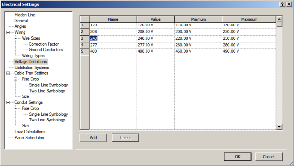
Figure 14.7 Voltage definitions for a project
Distribution Systems
You can define the distribution systems for your project in the Distribution Systems section of the Electrical Settings dialog box. The connectors in your electrical families need to coincide with the systems you define so that you can assign devices and equipment objects to a system. You can create single-phase or three-phase systems in delta or wye (or star) configurations and establish the number of wires for the system. The line-to-line and line-to-ground voltages for a system can also be defined. It is important to note that it is possible to create systems that do not actually exist in the industry. For example, you could create a three-phase system and set the line-to-line voltage to 120 volts and the line-to-ground voltage to 277 volts.
Use caution when creating distribution systems because they are very important for creating circuits for devices and equipment. Voltages can be assigned only as line-to-line or line-to-ground if they have been defined in the Voltage Definitions section. Figure 14.8 shows some examples of distribution systems created for a project.
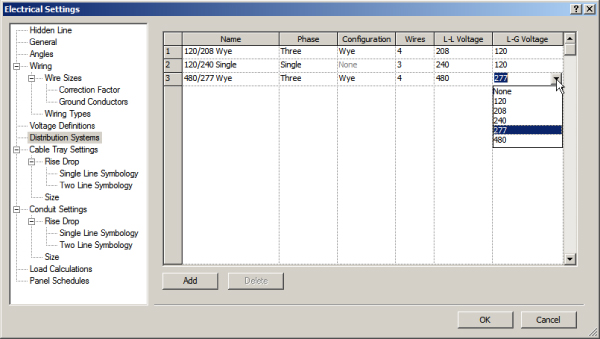
Figure 14.8 Distribution systems for a project
Load Calculations
In the Load Calculations section, you can establish demand factors and load classifications applied to the circuits in your project. The load classifications of the connectors in your electrical families determine which demand factor they will take on in your project. In this section, you can deselect the check box so that calculations for loads in spaces will not be done, which can improve the performance of your project. However, if you are scheduling spaces to view the engineering data they hold, you will not see any values derived from the model. You can use preset values if desired. To see the actual values based on the data within your model components, this setting must be turned on.
When you click the Load Classifications button in this section, the Load Classifications dialog box opens. In this dialog box, you can create new load classifications and define the demand factor used for them and a lighting or power load class for use with spaces. The available demand factors appear in the drop-down list, and the Demand Factors dialog box can be accessed by clicking the button next to the Demand Factor drop-down, as shown in Figure 14.9.
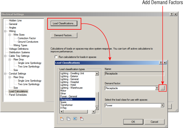
Figure 14.9 Load Classifications dialog box
It is best to keep your load classification names simple and descriptive because you will have to assign them to the connectors in your electrical families. When working in the Family Editor, you can use the Transfer Project Standards tool on the Manage tab to transfer load classification settings from your project or template file into the family to ensure coordination. For more on transferring project standards, refer to Chapter 25, “Creating a Project Template.”
There are many load classifications that come with the default electrical templates. You can create your own by using the buttons below the list, in the lower-left corner of the dialog box. The Spare classification cannot be assigned a demand factor and cannot be transferred to family files for use on connectors. It exists so that spares can be accounted for in your panel schedules.
In the Demand Factors dialog box, you can define the demand factors that are assigned to load classifications. The default electrical templates come with an extensive list of demand factors, and you can create your own by using the buttons in the lower-left corner of the dialog box. Figure 14.10 shows the Demand Factors dialog box. The Calculation Method section is where you determine how the demand will be calculated. Additional load can be added to the calculated result by selecting the check box at the bottom of the dialog box.
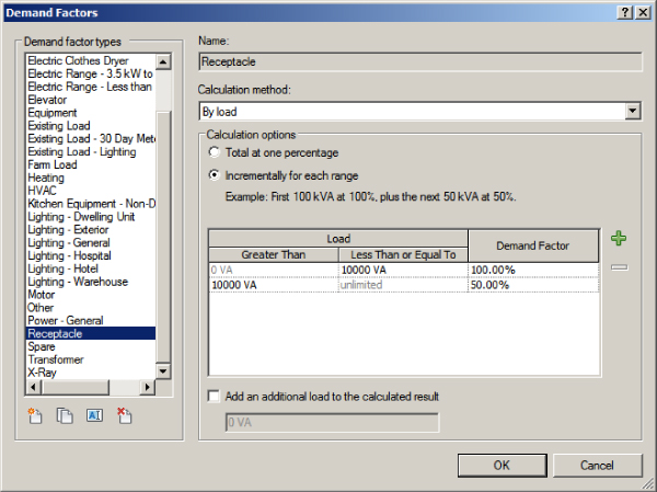
Figure 14.10 Demand Factors dialog box
There are three methods that can be used for calculation:
- Constant You use the Constant method to set a demand factor for all objects that use the load classification to which the demand factor is assigned. This is shown in Figure 14.11.
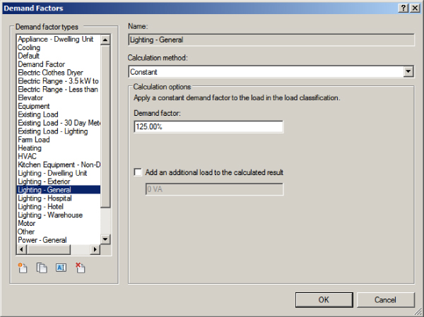
Figure 14.11 Demand Factors calculation methods
- By Quantity You use the By Quantity method to assign a demand factor to multiple items. You can assign different factors to ranges of items or the same factor to items, depending on how many there are. Figure 14.12 shows this method used for a motor load classification. The calculation option is set to calculate incrementally for each range. The ranges defined result in the first motor load being calculated at 125 percent and any other motors at 100 percent. Figure 14.13 shows this option used for clothes-dryer load classification. The option is set to assign the demand factor to all objects within a range that defines the quantity of objects. These settings will calculate the first four dryers at 100 percent, the next dryer at 85 percent, the next at 75 percent, and so on.
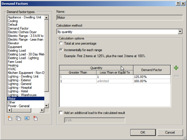
Figure 14.12 Incremental demand factor settings using the By Quantity method
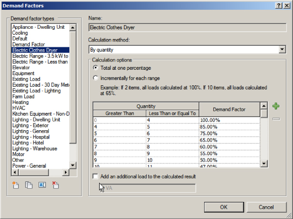
Figure 14.13 Total demand factor settings using the By Quantity method
- By Load You use the By Load method to assign a demand factor to different ranges of loads. You can assign different factors to ranges of loads or the same factor to the total load connected to a panel. Figure 14.14 shows the settings using this method incrementally for each range defined. These settings will calculate the first 10,000 VA at 100 percent and anything greater at 50 percent. The option to calculate the total at one percentage would be used if you wanted to set the demand factor for a total load range. For example, you could set the factor at 100 percent for 10,000 VA, meaning that if the total load on the panel were 10,000 VA, then all loads would be calculated at 100 percent.

Figure 14.14 Incremental demand factor settings using the By Load method
The Panel Schedules settings in the Electrical Settings dialog box allow you to assign a name for all spares and spaces in your panel schedules. You can choose to include spares in your panel totals and also merge multipole circuits into a single cell. Changing the Merge setting immediately affects your panel schedules. If you change the default name for spares or spaces, that name is applied only to new spares or spaces added to panels. Spares and spaces are automatically locked into position on creation and are highlighted in the panel schedule, as shown in Figure 14.15.
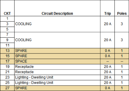
Figure 14.15 Spares and spaces in the panel schedule
Creating Circuits and Wiring for Devices and Fixtures
You can create circuits for devices or equipment to keep track of the loads within your panels. Circuits are the “systems” that are recognized for electrical design. You can create a circuit for devices or fixtures without selecting a panel so that, at a minimum, you have removed them from the default system and therefore your project file performance will not suffer.
When you are working in Revit MEP 2016, circuits and wires are not the same thing. Circuits are the logical connection between elements, similar in terms to HVAC, piping, and plumbing systems. Electrical circuits and systems are unique in Revit in that they do not require physical connections as the other disciplines do. Wires are a schematic, annotative representation of the means to make the connection only, meant to help the contractor understand what approach was intended for wiring in certain conditions.
As you learned at the start of this chapter, the type of circuit that you can create for a device depends on the properties of the connector in the device family, and the most important property is System Type, which defines the kind of circuit that can be created for the device. Figure 14.16 shows the properties of a connector in a receptacle family, along with the various parameters that can be assigned to the connector, which also define the type of circuit that can be created for the family, such as voltage and number of poles.
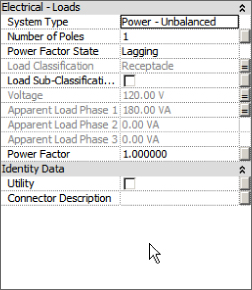
Figure 14.16 Device connector properties
When you select a device in your model, the Create Systems panel of the contextual tab displays a button that allows you to create the type of circuit that matches the properties of the connector in the selected family. If there are multiple connectors in the selected device, a button is available for each type of connector. In Figure 14.17, a floor box containing a power and data connector is selected.
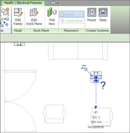
Figure 14.17 Create Systems panel of the contextual tab for a selected device
Clicking a button on the Create Systems tab creates a circuit for the selected device and changes the ribbon to the Modify | Electrical Circuits contextual tab. On this tab, there are tools to edit the circuit or to select a panel for the circuit. The properties of the circuit can be seen in the Properties palette when this tab is active. Click the Select Panel tool on the System Tools panel of the tab to choose a panel for the circuit—you can select the panel by clicking it in the drawing area, or you can use the drop-down on the Options Bar and select the panel by name. Only panels with a distribution system that matches the connector properties of your family will be available in the drop-down list. That includes the secondary side of transformers, so it is important to name your equipment and panels so that they are easily identified, as shown in Figure 14.18.
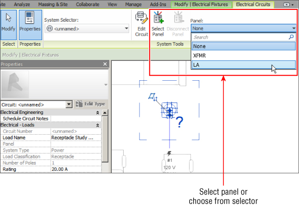
Figure 14.18 Panel drop-down list on the Options Bar when selecting a panel for a circuit
When you select a panel for the circuit, a dashed box appears in the drawing area that encompasses the components of the circuit, and a dashed line with an arrow indicates the home run to the panel. Clicking one of the buttons on the Convert To Wire panel of the contextual tab converts the indicated home run to wire. You have two choices for the graphical type of wire: Arc Wire or Chamfered Wire. Arc wiring can be used for straight lines between components if that is your standard. Figure 14.19 shows the indicated home run (top) and the result of clicking the Arc Wire button on the Convert To Wire panel (bottom).
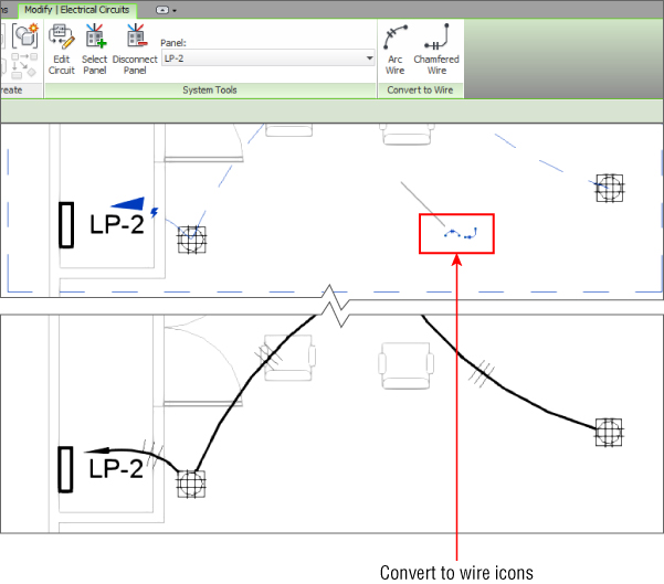
Figure 14.19 Indicated home run for a circuit (top); wire automatically generated by clicking the Arc Wire button on the Convert To Wire panel (bottom)
When you select multiple devices or fixtures with the same connector type, the button to create a circuit becomes available on the contextual tab. This allows you to select all the elements for a circuit and create the circuit in one step. An icon appears in the drawing area to convert the indicated wire to arc- or chamfer-type wiring, which can also be seen in the top of Figure 14.19. This keeps your cursor in the drawing area for improved efficiency.
Some of your elements may have more than one connector of the same type. When you select an element with multiple connectors and click the button to create a circuit, a dialog box appears that allows you to select the connector for which you are creating the circuit. Figure 14.20 shows this dialog box for a receptacle with two power connectors. Once you have chosen a connector, you can complete the process of creating a circuit. When you select the device again, you still have the option to create a circuit for the remaining connector.
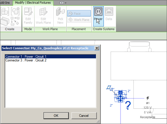
Figure 14.20 Select Connector dialog box
When you are creating circuits for lighting fixtures, it is important that the properties of the connector in the switch family match those of the connector in the lighting fixture family, except for load. If you use a Controls system type for the connector in your switch families, you cannot add it to the circuit for the light fixtures, but you can still draw the wiring from the lights to the switch. If your switch does not have a connector at all, you would have to use detail or model lines to represent the wiring from a fixture to the switch, which is not a workflow that I would recommend. In this instance, edit the family in question and add an electrical connector. When using the Wire tool to draw from a fixture to the switch or from the switch to a fixture, a home run is created when you connect to the fixture.
Editing Wiring
If the wiring that is automatically generated is not drawn exactly as you would like, it can be edited. When you select a wire, grips enable you to change the wire's arc and location. Right-clicking the wire also gives you the ability to add vertices to or remove them from the wire, giving you even more control over its final appearance.
The small blue circles that appear near the ends of the wire are grips for changing the end points of the line that represents the wire. These Change End Offset grips do not represent the point where the wire is connected; they are only the graphical representation of the wire. The actual point of connection is indicated by the connector ![]() symbol. The Change End Offset grips allow you to show the wire from any point on the device or fixture regardless of the location of the connector. Occasionally, the connection point grip and the Change End Offset grip are in the same place. You can use the Tab key to toggle between them for selection.
symbol. The Change End Offset grips allow you to show the wire from any point on the device or fixture regardless of the location of the connector. Occasionally, the connection point grip and the Change End Offset grip are in the same place. You can use the Tab key to toggle between them for selection.
The larger blue circle with two lines tangent to the end points of the wire is for changing the arc of the wire. The + and – grips that appear near the wire are for adding or removing hot conductors, respectively. These are discussed later in this chapter. Figure 14.21 shows the editing grips for a wire.
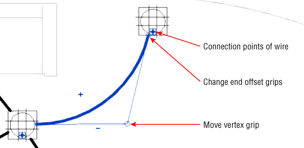
Figure 14.21 Wire-editing grips
The wire you can see on the left side of Figure 14.22 can be edited with its grips so that it does not interfere with other devices that are not part of the circuit. The edited wire is shown to the right of Figure 14.22. The end offsets are changed, and the arc of the wire is reversed for a cleaner-looking drawing.
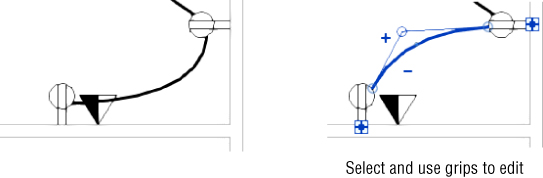
Figure 14.22 Wire that needs to be edited (left); the results of using the grips to change the appearance of the wire (right)
You can also use this procedure for lighting fitting circuits, as indicated in Figure 14.23, which also demonstrates the use of the chamfered wire.
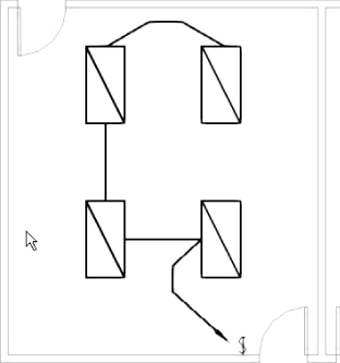
Figure 14.23 Editing lighting wiring
The wire you create by using Convert To Wire uses the same type as the wire you last created in your project, or the default wire type is used if you haven't drawn any. You can change a wire type by selecting it and choosing a new type from the Type Selector in the Properties palette. You can change all the wires for a circuit by editing the properties of that circuit.
Editing Circuits
When you select a device or fixture that has a circuit, the Electrical Circuits contextual tab appears with tools for editing and managing the circuit. If the device you have selected contains multiple connectors and circuits, the System Selector drop-down allows you to choose which circuit you would like to edit.
Click the Edit Circuit button to add or remove elements from the circuit. When you click the Edit Circuit button, the Edit Circuit contextual tab appears. All items that are not part of the circuit turn to halftone in the drawing area, including annotation and wiring, while elements of the circuit remain as normally displayed. The Add To Circuit button is automatically active when you click the Edit Circuit button. You can click any device or fixture in your view to add it to the circuit. You can also select devices or fixtures from other locations if you have multiple views of the model open. If you select an element that does not have a connector that matches the distribution system of your circuit, you receive a warning dialog box, and the element is not added to the circuit. Figure 14.24 shows a warning displayed as a 277-volt receptacle is selected to be added to a 120-volt lighting circuit.
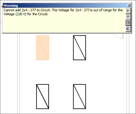
Figure 14.24 Circuit warning
When you select a device or fixture that has a connector matching the distribution system of the circuit to which you are adding an item, the display of the device or fixture changes from halftone to normal. You can click the Remove From Circuit button on the Edit Circuit contextual tab to remove items from the circuit. Once you have finished adding or removing items from a circuit, click the Finish Editing Circuit button to complete your changes. If you have wiring drawn to show items on a circuit and you remove some of the items, the wiring will not be removed from the view.
Another method for adding or removing objects to a circuit is to select the object and right-click its connector grip. If you do not have your cursor over the connector grip when you right-click, you will get a menu with tools for visibility control. Right-clicking the connector will give you the same menu but with additional tools for circuiting. Select the Add To Circuit option from the menu, and click any device or fixture that is part of the circuit that you want to connect to (Figure 14.25). You also have the option to create a new circuit from the context menu.
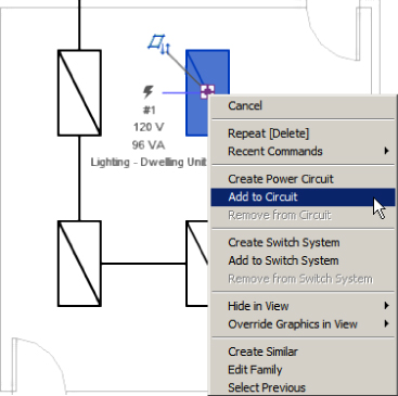
Figure 14.25 Add To Circuit
When you select an element on the circuit to which you want to add your device or fixture, you are given the option to automatically generate wiring that shows the added device as part of the circuit.
Selecting a device that is already part of a circuit and right-clicking its connector gives you a menu with the option to remove the element from the circuit. Removing a fixture or device from a circuit does not delete any wiring connected to it, but the wiring may change depending on the location of the removed element in the circuit. Figure 14.26 shows how wiring can be affected when a device is removed from a circuit. The receptacle in the lower-right corner was removed from the circuit. The receptacle in the upper-right corner is still part of the circuit, so the wiring has changed to a home run. Also, the wire from the unconnected receptacle to the one on the left has changed to a home run because it is not part of the circuit but has a device downstream that is part of the circuit. In any case, removing elements from a circuit usually requires some cleanup of the wiring.
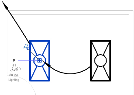
Figure 14.26 Wire changed by removing a device from a circuit
The workflow for creating circuits can be easily learned and will become second nature to your design and modeling processes. Practice creating circuits by doing the following:
- Open the
RMEP2016_Ch14_Dataset.rvtfile fromwww.sybex.com/go/masteringrevitmep2016. - Open the Power floor plan POWER - First Floor. Select the four receptacles in Office 104. Click the Power button on the Create Systems panel of the Modify | Electrical Fixtures tab.
- Notice that the panel should have already been selected; if not, make sure it is set to Panel LA.
- Click the Arc Wire button on the Convert To Wire panel of the Electrical Circuits tab.
- Click the Tag By Category button located on the Tag panel of the Annotate tab. Deselect the Leader box on the Options Bar, and select the home run created for the circuit. Click the Modify button on the ribbon to exit the Tag command.
- Repeat steps 1–5 for the three duplex receptacles in Office 103.
- Select the quadruplex receptacle in Office 103. Right-click one of the connector grips. Select the Add To Circuit option from the menu. Click one of the duplex receptacles in Office 103. Click the arc-type wiring grip that appears. Select the quadruplex receptacle again, and right-click the other connector. Select the Add To Circuit option from the menu. Click one of the duplex receptacles in Office 103. Press the Esc key to finish.
Figure 14.27 shows how the wiring and tags should appear.
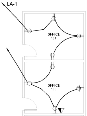
Figure 14.27 Receptacle wiring and tags
- Open the Lighting floor plan LIGHTING - First Floor and create a power circuit for the lights in Office 104 by selecting the two lighting fixtures in the plan and click Create Power System. Select panel HA from the Panel drop-down on the System Tools panel, and click on the temporary arc to generate the wiring.
- Click the Tag By Category button located on the Tag panel of the Annotate tab. Ensure that the leader option is not selected on the Options Bar, and select the home run created for the circuit. Click the Modify button on the ribbon to exit the Tag command.
- Repeat steps 9 and 10 for the lights in Offices 103 and 102.
- Select the home run for the Office 102 circuit, and using the vertex grip, drag the wire up until it connects with the left light fixture in Office 103.
- Select the double home run from the light fixture in Office 103, and use the vertex grip to drag the wire up to the left light fixture in Office 104. Notice that a multicircuit run of wiring has been created.
- Select the switch in Office 102, and right-click its connector. Select the Add To Circuit option from the menu, and select one of the light fixtures in the room. Click the arc-type wiring grip to create the wire. Use the wire-editing grips to adjust the display of the wire.
- Repeat step 14 for Offices 103 and 104. Figure 14.28 indicates the linked wiring and tag appearance.
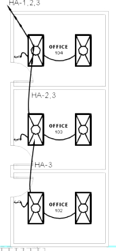
Figure 14.28 Wiring to Lighting Fixtures
Drawing Wires Manually
To create the wiring for your circuits, you don't have to use the automatic wiring approach. You can quickly and easily draw wires manually. In some cases, it may be easier to draw the wire than to make adjustments to automatically generated wiring; for example, some offices show wire only on home runs, which would mean deleting a lot of extraneous wiring if they used the automatic feature.
To draw wiring, click the Wire button on the Systems tab. The bottom half of the button is a drop-down list with options for the style of wire you can draw. You can draw arc or chamfer wires automatically and spline wires manually. These options indicate only how the wire is drawn and have nothing to do with wire types or the electrical properties of the circuit or devices. Once you have selected a wiring style, you can choose a wire type from the Type Selector in the Properties palette. You can use the Tag On Placement button on the contextual tab to place a tag on the wire as you draw it.
You can draw wire anywhere in your plan views, so it is important that you snap to the component geometry of the elements for which you are showing the wire. If you draw a wire between two symbols, it may appear that the wire connects them, but if the wire is not “attached” to the devices, the wire does not move when the devices move.
To ensure that your wire is connected to an element, you need to snap to a point on the component geometry, not the symbol that represents the component. As long as your cursor is over some part of the component when you start your wire, the wire connects to the component at the electrical connector. Figure 14.29 shows a wire being drawn from a mechanical unit by clicking the edge of the unit (1); the wire then connects to the electrical connector of the unit (2), your second click produces the first part of the wire (3), and finally the final click creates the wire as you would expect to see it (4)
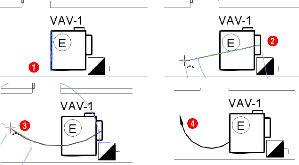
Figure 14.29 Drawing a wire from a unit
The mechanical unit shown in Figure 14.29 has an electrical connector, so the equipment connection and disconnect switch symbols on the electrical drawing do not require a connector or any electrical properties. The wiring to this unit can be modified to be shown from the disconnect switch symbol while maintaining its connection to the unit, as shown in Figure 14.30.
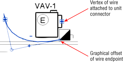
Figure 14.30 Modified wire graphics
Arc- and chamfer-style wires are drawn by clicking a start point for the wire, a middle point, and an end point. To draw wire between two components, start your wire at one component, click somewhere between the two items, and click the second component to end the wire. Spline-style wires allow you to click several times between elements.
To draw a wire home run, you simply start a wire at the connector of a device or fixture and leave the other end of the wire unconnected. If the component from which you draw is assigned to a circuit, the wire shows an arrowhead indicating a home run (if the electrical settings permit it). If the component is not assigned to a circuit, the wire appears without an arrowhead until the element has been assigned to a circuit.
Drawing a wire between components does not mean that they are on the same circuit. If you draw a wire from a component that is on a circuit to another component that is not on a circuit, the second component is not added to the circuit. You can draw wire between components that are not on the same circuit, creating a multicircuit run of wiring. A home run wire is displayed between components that are on different circuits, which can be seen in Figure 14.28.
You can show multiple home runs from a single component that has multiple connectors. The automatic wire option works for each circuit that you create in turn. To do so, use the following steps:
- Select the component and click the button on the Create Systems panel to create a circuit.
- Choose a connector from the dialog box that appears, select a panel for the circuit, and choose a wire style from the Convert To Wire panel on the contextual tab.
- Modify the wire using the grips so it does not get completely overwritten with the next.
- Select the component again to create a circuit for the next connector and once again choose a wire style.
You can use a wire tag to confirm that the home runs are not connected to the same connector, as shown in Figure 14.31.
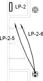
Figure 14.31 Multiple home runs from a single device
Controlling Wire Display
Using a filter to control the display of wires in your project is an effective method for distinguishing between different wire types. As mentioned earlier, creating wire types in the electrical settings of your project makes it easy to isolate specific wires for visibility control. This allows you to show wire such as underground, overhead, or low-voltage wire in the same view and be able to visually identify the different types. For more information on the use of filters, refer to Chapter 2, “View Filters and View Templates.”
Managing Circuits and Panels
By creating circuits for your devices, fixtures, and equipment, you have the ability to manage the properties of those circuits and the panels to which they are connected. You can also manage the location of circuits within your panels to balance loads and track the total electrical load for your project. The electrical connectors in your families determine some of the properties of the circuit to which they are connected.
Circuit Properties
To access the properties of a circuit, select an element connected to it and then select the Electrical Circuits contextual tab. If the selected component has multiple circuited connectors, you can choose which circuit properties to access by selecting the circuit from the System Selector drop-down list. The properties of the circuit are displayed in the Properties palette. Click the Properties button on the ribbon to access the Properties palette if it is not already active. Because most of the data comes from the electrical characteristics of the connector and the distribution system, many of the parameters of the circuit are grayed out and are not editable. Revit takes the load information from the components on the circuit and calculates the apparent load and current as well as the voltage drop and wire size. You can change the type of wire used for the circuit by editing the Wire Type parameter. This defines the type of wire used for calculations.
You can change the Load Name parameter to give the circuit a more descriptive name that appears in the panel. When you are creating a circuit for components and the load exceeds 80 percent of the circuit-breaker rating, you get a warning. It does not prevent you from overloading a circuit, however. The default breaker size for circuits is 20 amps. The Rating parameter indicates the circuit-breaker size for the circuit and can be changed to meet the requirements of your circuit.
People express anxiety about computers making too many decisions or replacing them. But choosing the size of circuit breakers is the realm of the engineer; it's your decision. Revit is meant to help you resolve circuits that are overloaded or could become overloaded by being designed too close to ideal tolerances. Revit helps keep track of information and provides us with results that help us make informed choices about equipment and circuit design.
Wire Properties
When you select a wire in a model, you can access that wire's properties in the Properties palette. Clicking the Edit Type button in the Properties palette opens the Type Properties dialog box, which displays the parameters for the wire as defined in the electrical settings for the project. You can add information such as a description or type mark to the wire type.
The instance properties of the wire control the display of tick marks and the number of conductors for the circuit. There are three options for the Tick Marks parameter:
- Calculated This is the default value for wires, and it indicates that the number of conductors is determined by the circuit and distribution system properties, regardless of whether the tick marks are displayed.
- On Selecting On displays tick marks on the selected wire.
- Off Selecting Off turns off the display of tick marks on the selected wire.
The number of conductors can be increased or decreased by editing the values of the Hot, Neutral, and Ground Conductors parameters. You can change the number of hot conductors by using the + and – editing grips that appear in the drawing area when you select a wire. The location of the tick marks on a wire can be changed by clicking the solid blue dot that appears at the center of the tick marks when a wire is selected.
Panel Properties
In the instance properties of a panel, you can provide information about it that appears in the panel schedule. You can add notes to the header or footer of a panel schedule by clicking the Edit button in the Schedule Header Notes and Schedule Footer Notes parameters, respectively. The Mains parameter is for indicating the size of the main circuit breaker and does not affect any load calculations. The Max #1 Pole Breakers parameter allows you to assign the number of poles in the panel. You can also indicate the short-circuit rating, enclosure type, and any modifications by editing the respective parameters.
You can define how the circuit tags will appear in your drawings by editing the Circuit Naming, Circuit Prefix, and Circuit Prefix Separator parameters. The standard wire tag is a label that displays the circuit number. There are four options for circuit naming:
- Panel Name This option places the name of the panel in front of the circuit number when a wire or device is tagged. You can use a separator such as a dash between the panel name and circuit number by using the Circuit Prefix Separator parameter.
- Prefixed This option places the prefix defined in the Circuit Prefix parameter in front of the circuit number when a wire or device is tagged.
- Standard This option does not add any additional information to tags that display the circuit number of a selected wire or device.
- By Phase This option displays the Circuit Naming By Phase label defined in the Electrical Settings in front of the circuit number listed in the panel schedule.
Figure 14.32 is an example of circuits where the panel has been set to create circuit naming by phase. The panel reference is generated by a label defining the name.
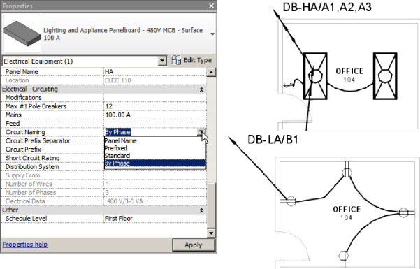
Figure 14.32 Panel circuit-naming options
When you select a panel, the Modify | Electrical Equipment contextual tab appears. The Edit Panel Schedule button, available when a panel schedule has been created for the panel, allows you to change the location of circuit connections within the panel. In this view of the panel, you can change the fonts used in the cells to match your standards. Select a cell or multiple cells, and right-click to change the font. In the Edit Font dialog box, you can choose a font and then its size, style, and color (see Figure 14.33).
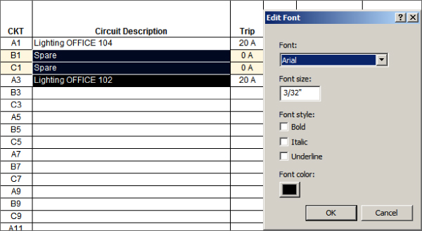
Figure 14.33 Edit Font dialog box for a panel schedule
You can change the name of a circuit by simply editing the value in the cell. This updates the value of the Load Name parameter of the circuit. Once you have made changes to circuit names, and you select a cell that has been edited, the Update Names button on the ribbon becomes active. Clicking this button returns the circuit name to the default, which includes the load-classification name and the location of the object. Take care when using this.
You can change the size of the circuit breaker for a circuit by editing the cell in the panel schedule. This updates the value of the Rating parameter of the circuit. If you edit the breaker to a size that causes the circuit to be overloaded, you receive a warning dialog box.
To balance the loads in a panel, you can click the Rebalance Loads button on the ribbon. This moves circuits around in the panel to achieve the most balanced configuration possible across the phases. This may cause unwanted results, so use caution with this feature. For example, you may have a multicircuit wiring run that occupies circuits 1, 3, and 5, but after rebalancing the loads, the circuits end up as 1, 4, and 18. It may also move multipole circuits to locations where they normally would not be placed. To avoid this scenario, you can use the Group/Ungroup button that becomes active when you select multiple circuits (see Figure 14.34). This maintains the order of the circuits and moves them as a single unit. Grouped circuits are indicated with a blue, dashed box around them. Selecting any cell within a group of circuits and clicking the Group/Ungroup button removes all the circuits from the group, not just the selected cell or cells.
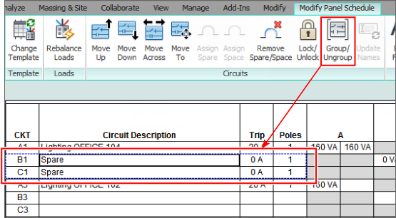
Figure 14.34 Grouping circuits
You also have the option to relocate circuits manually. To change the position of a circuit in a panel, click the circuit number. This activates the move buttons on the Circuits panel of the tab. You can move the circuit up or down the side of the panel it is on. When you move a circuit up or down to a space that already contains a circuit, the two circuits change places. Circuits can also be moved from one side of the panel to the other.
New to Revit 2016 is one other option: the ability to move a circuit (or a group of circuits) to a different position on the board. Simply make your selection and choose Move To. The circuit(s) is highlighted in green and can be moved to a suitable slot, as shown in Figure 14.35. A circuit cannot be moved to a space, spare, or another occupied circuit location.
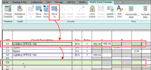
Figure 14.35 Moving a circuit
When you select a panel for a circuit, the first available circuit in the panel is found and the circuit is placed there. Spares and spaces can be added to occupy circuits in the panel. Because you cannot choose the circuit number for a circuit when it is created, when you add a circuit to the panel the circuits occupied by spaces or spares are not used.
To insert a spare or space, select an unoccupied circuit number, and click the Assign Spare or Assign Space button on the Circuits panel of the tab. A light brown background is applied to the cells for the circuit number. This background is a visual indication that the circuit is locked. A locked circuit cannot be moved in the panel. You can edit the name of a locked circuit and also change its breaker size. Any occupied circuit in the panel can be locked by using the Lock/Unlock button on the Circuits panel of the tab. The only way to remove a spare or space is to select it and click the Remove Spare/Space button on the Circuits panel of the tab.
The ability to lock circuits in a panel comes in handy when you are relocating circuits. You can lock circuits so that when others are moved, the locked circuits remain in place and are not swapped with the circuit you are moving.
Other Panels and Circuits
Circuits can be created for any of the categories of electrical systems. Wire types can be created to distinguish these systems visually if wiring is shown. The panels for these systems can be used to manage the circuit locations. You can create panel schedule templates for the various types of panel schedules that you use in your projects. Figure 14.36 shows the Edit Circuits dialog box for a telephone terminal block used as the panel for the telephone circuits in a project.
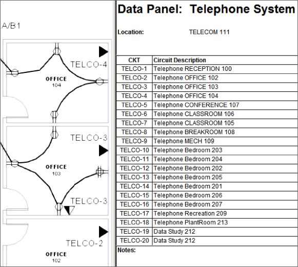
Figure 14.36 Telephone circuits
Although telephone wiring is not normally shown on a typical set of construction documents, creating these systems provides you with information that can help in making design decisions. This type of information could later be modified to represent the as-built conditions of your project, which could then be useful for facilities maintenance. It is about putting the I in your BIM project.
Using Schedules for Sharing Circuit Information
A panel schedule is a special type of schedule that is automatically generated from the data within the panel objects. You can create a panel schedule in one of two ways. After selecting a panel, on the Modify | Electrical Equipment contextual tab click the Create Panel Schedules button. Clicking this button allows you to select a template to be used for the panel schedule. The alternative is to use the Panel Schedules option on the Analyze tab. This option lets you create the schedule without prompting for a template. Both options are shown in Figure 14.37.
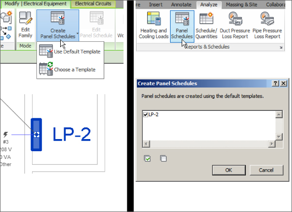
Figure 14.37 Creating panel schedules
Once you have chosen a panel schedule template, the panel schedule appears in the Project Browser, as shown in Figure 14.38.
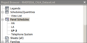
Figure 14.38 Panel schedules shown in the Project Browser
You can access the panel schedules by double-clicking them in the Project Browser or by selecting the panel in a view and clicking the Edit Panel Schedule button. You can change the template used for a panel schedule by right-clicking it in the Project Browser and choosing the Change Template option.
You can place panel schedules on your sheets, like any other view, by dragging and dropping them from the Project Browser. When you place a panel schedule onto a sheet, it is formatted according to the settings defined in the panel template. Changes made to the circuits in your model or in the Edit Circuits dialog box of the panel automatically show up in the panel schedule. Changes made to the panel schedule template that define the size and appearance of the schedule are automatically applied to the schedule on a sheet. You can snap to the border of a panel schedule to align your schedules on a sheet.
You can create schedules for panels and circuits that can be used to extract information about your project. Organizing the data contained in your project regarding electrical loads can help you make design decisions and keep your design coordinated with other disciplines. Schedules can also be created to supplement the panel schedules that are generated.
Circuits hold a host of useful data that can be scheduled for project coordination and design. Figure 14.39 shows a schedule of electrical circuits that displays information that can be used to verify circuit locations as well as length, voltage, breaker size, and wire size. This type of schedule may be useful because you can display and manage information about the circuits that may not appear in your panel schedules. Having this information in a schedule makes it easy to check your design and make any necessary changes.
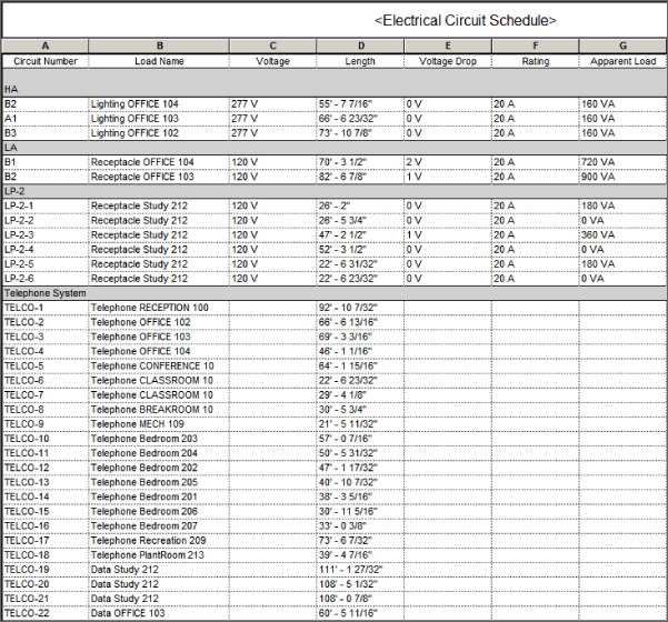
Figure 14.39 Electrical circuit schedule
The Bottom Line
- Establish settings for circuits and wiring. Proper setup of a project's electrical characteristics is an important part of the workflow when you're creating circuits and wiring. Settings can be stored in your project template and modified on an as-needed basis.
- Master It The distribution systems defined in a project make it possible to connect devices and equipment of like voltages. Do you need to have voltage definitions in order to create distribution systems? Why or why not?
- Create circuits and wiring for devices and fixtures. Circuits are the systems for electrical design. Wiring can be used to show the connection of devices and fixtures in a schematic fashion.
- Master It Circuits can be created for devices or equipment even if they are not assigned to a panel. Circuits can then be represented by wiring shown on construction documents. Give two examples of how you can add a device to a circuit that has already been created.
- Manage circuits and panels. With the relationship between components and panels established, you can manage the properties of circuits and panels to improve your design performance and efficiency.
- Master It While checking the circuits on a panel, you notice that there are only 14 circuits connected but that the panel has 42 poles. How can you reduce the amount of unused space in the panel?
- Use schedules for sharing circuit information. Panel schedules can be used on construction documents to convey the load information. Schedules can also be created for use as design tools to help track electrical data.
- Master It The information in Revit panel schedules may not meet the requirements of your document or design standards. Describe how you can use the data within your Revit model to provide the required information.