Chapter 20
Creating Light Fixtures
Lighting fixtures can be located anywhere in a building. They hang from ceilings and structures; they are mounted in floors, walls, and stairs; and they even stand on their own. With the Autodesk® Revit® MEP 2016 software, you can make any shape or form into a lighting fixture family so that, if your project requires it, you can create a unique fixture. However, the majority of lighting fixtures used in building design consist of a few basic shapes. Unless your project requires it for visualization, there is no need to go into great detail when creating the geometry of your lighting fixture families. Keeping their design simple will enable you to focus more on the computable data within your fixture families.
Lighting fixtures are true BIM families because they can be used not only to create a coordinated 3D model but also as a design tool. They can display the output of light for a specific fixture type by referring to separate manufacturer-specific IES data files. The photometric data for a specific lighting fixture can be applied to a lighting fixture family regardless of the geometry of the family. This gives you the freedom to build families for the basic size, shape, and mounting options of lighting fixtures and then apply manufacturer-specific data to them for an accurate lighting design. Lighting fixture families can also contain electrical data, which allows for connection to distribution systems.
There are many options for the level of detail and data you can put into your lighting fixture families.
In this chapter, you will learn to do the following:
- Create different types of lighting fixture families
- Use a light source in your lighting fixture families
- Create and manage fixture types and parameters
- Use lines and symbols to represent lighting fixtures
Understanding Types of Lighting Fixture Families
Prior to creating a lighting fixture family, it is important to know how it will be used in your projects. The first thing to consider is how the fixture will be hosted in your model. Lighting fixture families can be hosted by specific building elements such as walls or ceilings or by any three-dimensional face within your model. You can also create lighting fixture families that do not require a host. Each hosting option determines how the geometry of the fixture is to be oriented in the family file. It is also important to realize that a family created with one type of hosting template cannot be exchanged for another, even though they may be of the same category. For this reason, planning, naming conventions, and training for staff are all important.
There are family template files (with the.rft extension) for different types of hosted lights. You can also use one of the generic family templates and later categorize the family as a lighting fixture. When you use a lighting fixture template, a reference plane for the elevation of the light source is already included. Using a generic template will require you to add a reference plane for the light source if needed.
Nonhosted or Level-based Lighting Fixtures
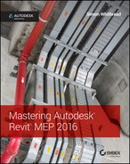
Nonhosted lighting fixture families are useful in areas that do not have a ceiling or for freestanding lights. They can be given an offset to the level at which they are inserted to show them above the floor. They are also useful for wall-mounted lights, when you need to show a symbol on your drawings instead of the actual fixture. The symbol can be nested into your fixture family without concern for the annotation orientation because the fixture will always be vertical. One example of this use is a wall-mounted exit light. Figure 20.1 shows an exit light family that has a nested annotation. The geometry of the fixture is modeled to appear correctly when placed adjacent to a wall, whereas the annotation is nested to display in plan views.
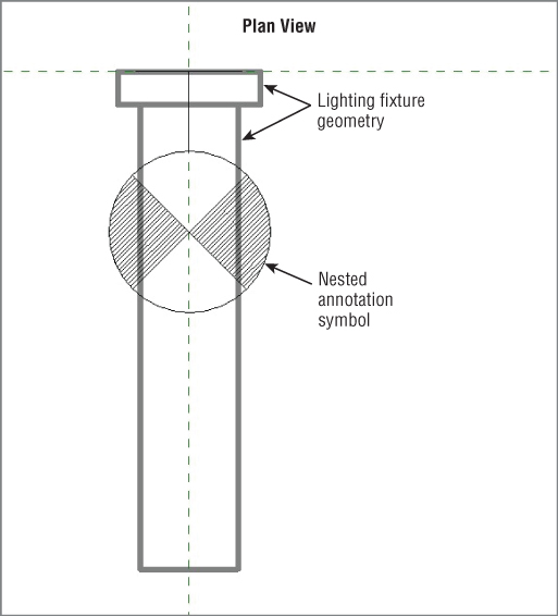
Figure 20.1 Nonhosted exit light family
The drawback to this scenario is that, although you show the fixture adjacent to a wall, if the wall moves the fixture does not move with it. This can cause inaccuracies on your drawings and therefore requires manual editing of the fixture locations. Thus, you must carefully consider the types of light fixture families used with this method.
As with any family you create, the insertion point is an important consideration when building the geometry of a lighting fixture. When you create any type of fixture with the Generic Model.rft family template, Revit opens four views automatically, with the floor plan view as the active view. Figure 20.2 shows the open views by accessing the Switch Windows button on the View tab
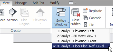
Figure 20.2 Switch Windows
The intersection of the reference planes in the Floor Plan: Ref. Level view defines the insertion point of the family. Be sure to build the fixture geometry around the insertion point in a manner that makes it easy to place the fixture into your models. Fixtures that need to be adjacent to elements are easier to insert when their geometry is properly oriented with the insertion point. Also, take into consideration how the fixture may be rotated in your model.
Because of the potential complexities of creating a new family and maintaining company standards and consistency, it can be useful to have a standard “family planning” sketchpad, where design, parameters, and reference planes can all be drawn out before committing yourself to an actual family. Figure 20.3 shows an example of a form used for planning the construction of a Revit family.
Figure 20.3 Sample family planning design form
Creating geometry in the Ref. Level view places it at the reference level. The reference level in a family is a placeholder for the project level when you insert the family into a project. That is how a light fixture inserted on the second level of your project is associated with the second level. Therefore, the elevation or offset that you apply to the fixture is relative to the level at which it is placed. If you are creating a nonhosted lighting fixture that you want at a specific elevation when you insert the family, you can build the geometry at the desired elevation. This has the potential to cause confusion when using the Offset parameter, so a best practice is to use the reference level.
If you do not want to use the Offset parameter of an instance when working in a project file, you can control the elevation of a fixture by placing a reference plane in the family. The plane can be dimensioned and associated with an instance parameter to edit and manage the elevation of the fixture easily. Draw a reference plane in an elevation view when working in the Family Editor. Be sure to give the plane a name so that you can select it later as the host for your fixture geometry.
You can set the reference plane as the current plane for modeling by using the Set button on the Work Plane panel of the Create tab on the ribbon. This lets you choose a plane, such as the one you just created, to model your geometry on. If you have already created the geometry for your lighting fixture, you can select it and click the Edit Work Plane button on the Work Plane panel of the contextual tab. In the Work Plane dialog box, click the Name radio button and choose the plane you created for the fixture elevation from the drop-down list (see Figure 20.4).
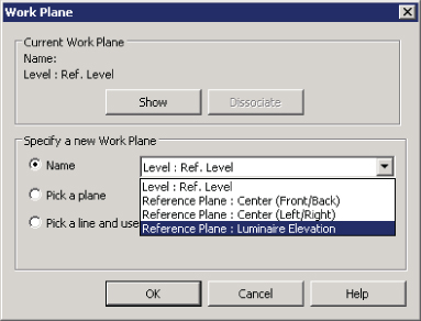
Figure 20.4 Choosing a new work plane for family geometry
Depending on the type of forms you use for the geometry, you may have to select them independently to change the plane they are associated with. You can select and change the work plane of different form types (extrusions, revolves, or blends) only if they are on parallel planes.
Because you can change the work plane of an item only to a parallel plane, select those items that have been created on the same plane or a parallel plane. If an extrusion is created while in an elevation view, it is associated with a vertical plane and cannot be moved to a horizontal plane. However, you can align and lock it to a horizontal plane.
Figure 20.5 shows an elevation view of a nonhosted lighting family. A reference plane has been created to define the fixture elevation. The geometry was created in the plan view, and its work plane was changed to the lighting elevation plane. The dimension has been associated to an instance parameter for fixture elevation. There are two schools of thought here. You could set this as a default 0′-0″ (0 mm), because you are always changing the offset for different ceiling heights. Or you could set it as 8′-0″ (2400 mm) if you want to have fittings coming in at a “default” ceiling height. Whichever you choose, you should keep it consistent throughout your library, and if you do follow through with this workflow, you will also need to edit every family you choose to bring in from any external source.
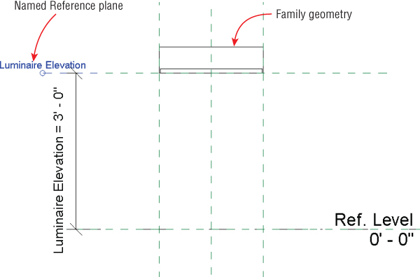
Figure 20.5 Nonhosted family with an elevation plane
Creating a fixture with an elevation parameter does not disable the functionality of the Offset parameter, so be sure that you and your users understand the difference. When your family is placed into a project, the offset is applied to the entire family, whereas the elevation is applied to the geometry within the family.
If you want your lighting fixture families to follow the slope of a surface such as a sloped ceiling, you need to deselect the Always Vertical parameter. This setting is found in the Family Categories And Parameters dialog box that you can access from the Create or Modify tab, as shown in Figure 20.6.
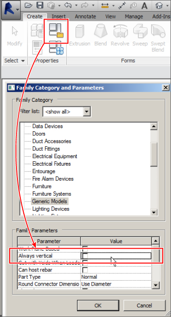
Figure 20.6 Always Vertical
Setting the family to Always Vertical causes the fixture to attach to its associated work plane in its normal orientation even if the plane is sloped. Deselecting the parameter causes your fixture family to follow the slope of its associated plane or level.
Any annotation symbols nested within the fixture family are displayed only in plan views that are parallel to the view they are created in, so they are not displayed if the fixture is mounted to a sloped plane.
Another useful setting for nonhosted families is the Work Plane-Based option found in the Family Category And Parameters dialog box. This setting allows you to create a family that does not require host geometry yet can be associated with a plane in a model.
Using this option gives you the ability to associate a family with a named reference plane in your model, in the same way that a face-hosted family attaches to a 3D face. You can change the host plane of the family at any time after placement in the model.
When placing a family of this type into your model, you have the choice of either Place On Work Plane or Place On Face (which is set by default). You can choose any named reference plane, even sloped planes, or any level in the project.
When used with the Always Vertical setting, the family attaches to a sloped plane; however, the geometry of the family remains vertical and does not follow the slope of the plane.
Face-hosted Lighting Fixtures
Creating face-hosted fixture families adds another level of coordination to your projects because the families move with their associated hosts. This keeps your fixtures at the correct elevations when ceiling heights change. Fixtures mounted to vertical host faces, such as walls, also move with changes to the vertical host locations. Face-hosted families can also be hosted by reference planes within the project. In an area with no ceiling, a reference plane or level can be created to host lighting fixtures at a specific elevation—or as described earlier, host to the level and change the offset.
To create a lighting fixture family that is face hosted, you can use the Generic Model face based.rft family template. Once you've opened it, you can change the category of the family by clicking the Category And Parameters button on the Family Properties panel of the Create tab. When you change the category to Lighting Fixtures, the Light Source parameter becomes available. Select the box if your fixture will have a light source to be used for rendering or lighting calculations (see Figure 20.7).
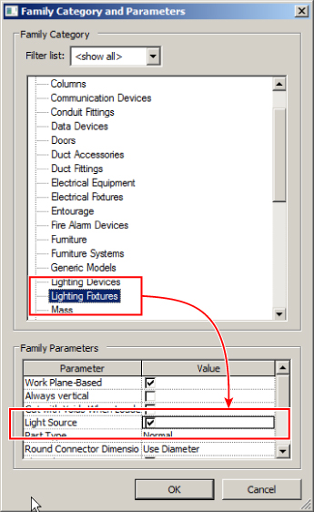
Figure 20.7 Family Category And Parameters dialog box
The face-based template contains a generic extrusion that is used as a reference for the host when the family is placed into a model. You can change the size of the extrusion, but you cannot delete it. The extrusion is necessary in order for your family geometry to know how to attach to its model host. It also allows you to indicate how void extrusions cut their host.
Face-hosted families also contain a reference level plane at the face of the placeholder extrusion. This face represents the face of a ceiling or wall host when the family is placed into a model. The placeholder extrusion face is locked to this reference plane and cannot be unlocked, so although you can associate the extrusion to another plane, it is not a good idea. Doing so will change only the thickness of the extrusion, which is not important.
To build a recessed lighting fixture, you want your extrusions to be inside the placeholder extrusion. Although the fixture looks upside down in the family file, it will have the correct orientation when hosted by a ceiling or reference plane in your project file, because the placeholder extrusion represents the host object when the family is used in a project. Surface- or pendant-mounted lights should be modeled adjacent to the face of the placeholder extrusion.
Face-hosted Families for Wall-mounted Lights
When creating a face-hosted family for a wall-mounted light fixture, you need to treat the placeholder extrusion as though it were a wall. When working in the Ref. Level plan view of the family, it is as though the wall has been laid flat on the ground and you are looking down at it. It is easy to assume that the distance from the edge of the placeholder extrusion to your geometry will be the mounting height of the fixture. That is not the case (see Figure 20.8).
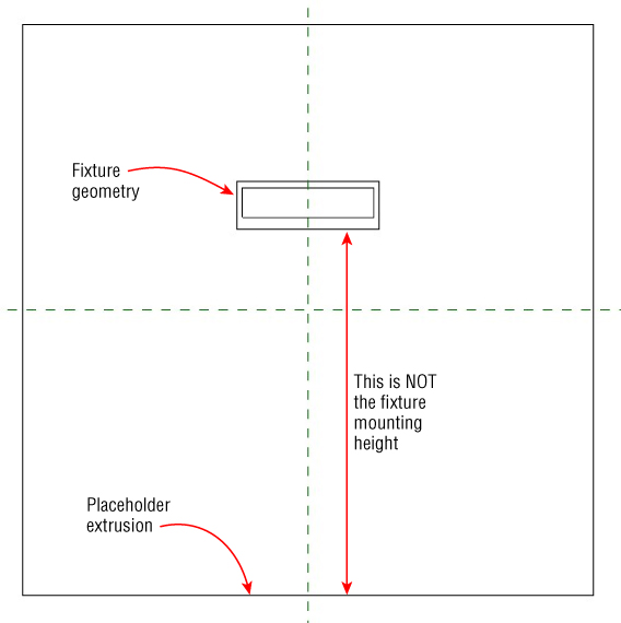
Figure 20.8 Face-hosted family for a wall-mounted light
Face-hosted families have a Default Elevation parameter used when the family is placed on a vertical face. When they are placed into a model on a vertical face, the Elevation Instance Parameter becomes active and is used to set the mounting height. The Default Elevation parameter is simply a starting point until an elevation is assigned after the placement of the family. You can set Default Elevation within the family file to any value that you want for the mounting height when the fixture is first placed into your project, but because of the functionality of the Properties palette, you may need to enter a value during initial placement. It is a type parameter, so you can use it to define different family types if desired. In the project environment, the Elevation parameter is active only when the family is placed on a vertical host. When a face-hosted family is placed on a horizontal host, the Elevation parameter is inactive and cannot be edited. Figure 20.9 shows a wall-mounted light that was placed into the model at an elevation of 4′-0″ (Default Elevation) and then given a mounting height of 7′-6″ (Elevation) after placement.
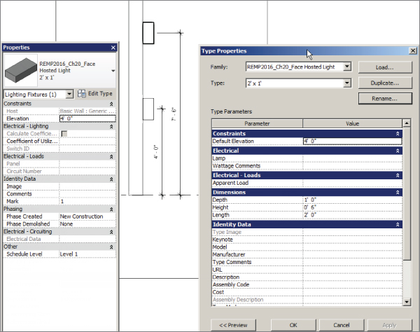
Figure 20.9 Wall-mounted fixture with an elevation
When you create an extrusion to represent the body of a light fixture that is to be hosted by a vertical face, it is often easier to create it in a left or right elevation view instead of the Ref. Level plan view. By doing so, the extrusion you create will be associated with the Center Left/Right reference plane. Additional reference planes can be added to create constraints for fixture length, depth, and width.
Fixture Types Based on Dimensions
When you are creating lighting fixtures, you first need to decide what type parameters are going to be used to determine the different types within the family. One common practice is to create fixtures based on their dimensions. This is a good starting point for developing a fixture library, and additional parameters can be added later to create more types within the family for more specific purposes.
For example, you can start by creating a recessed fluorescent troffer. Then, creating parameters for the length and width of the fixture allows you to make types in the family such as 2×4, 2×2, or 1×4. This is a generic method for creating fixtures, but it is useful for general modeling when lighting analysis or circuiting is not required. The depth of the fixture should also be considered because it is an important dimension for coordination of the space above the ceilings within a model.
This can be done for any kind of fixture you may use in a project, such as down lights, surface-mounted fixtures, and pendant fixtures. A library of generic (or “placeholder”) fixtures is useful in the preliminary design stages of a project. Early on you may not know exactly what fixtures will be used, but you can use these generic fixture families to represent the basic layout and design intent. Because they are categorized as lighting fixtures, you can easily replace them with the actual fixtures to be used when the decision is made. Just remember that you cannot replace face-hosted families with nonhosted ones by using the Type Selector. You have to place one type and remove the other manually.
Fixture Types Based on Fixture Performance and Lighting Characteristics
Having fixture families based on size and shape is a good start, but you also need fixtures that are defined by their specific uses and performance. This is especially true if you intend to use your Revit model for lighting analysis. It is a good practice to develop lighting fixture families that meet the design requirements of your Revit projects so you don't have to create a separate fixture family for every light fixture you use.
You can create families based on their performance and appearance. Not only does a parabolic fixture perform differently than a lensed fixture, it also looks different, so creating separate families for each type may be necessary. Appearance is important only if you are concerned with modeling to a level of detail that requires a visible difference between the two fixtures, but it may be easier to manage separate families than one family with several types.
With these fixtures, the dimensions are important for defining different types, but they do not need to define the family itself. You can create a parabolic troffer family with types such as 2×2 and 2×4, but you also want parameters to define the voltage, load, or number of lamps. Each type parameter that you add to a fixture family can determine a fixture type within that family. This allows you to use a unique IES file for each type.
There are many lighting manufacturers from which to choose when specifying your fixtures in a project. It is not necessary to have a library that contains each and every option. You can make a set of lighting fixture families that cover the basic fixture types and then modify them to manufacturer specifications as needed. Choose an IES file that meets the basic requirements for the fixture type as the baseline for that type of fixture. When you use the fixture in a project, you can get an idea of its performance prior to deciding which specific manufacturer and model number to use. Some people have resisted using Revit MEP for their projects because they think they have to make too many decisions early on in the project that they are unable to make. Using a baseline fixture type will allow you to move forward with the project and make the more specific decisions when necessary.
Figure 20.10 shows the types within a parabolic 2×4 light fixture family. The No. Of Lamps and Ballast Voltage parameters are used to determine the family types. A unique file is required for the Photometric Web File parameter for each variation in the number of lamps, but it is not required for each voltage.
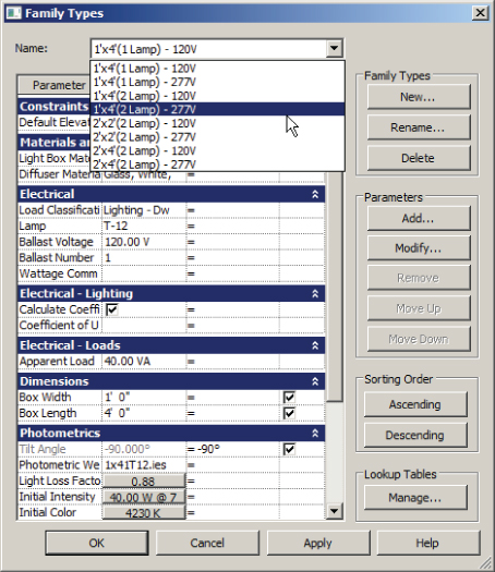
Figure 20.10 Lighting fixture family types
There is no right or wrong answer to how many light fixture families you should have. How you use the software and your design standards will help determine the types of fixture families you require. A minimum number of families that can be readily adjusted to the specifics of your project will be easiest to manage and maintain.
However you decide to create a fixture, it is important to build your fixture family so that when it is placed in a model, it can be associated with a Space object in order to provide the desired engineering data from calculations. A light fixture that is not inside or touching a Space object does not generate an average estimated illumination for that Space object. Figure 20.11 shows a group of fixtures placed higher than the upper limit of an engineering Space object; therefore, there is no illumination calculated for the Space object.
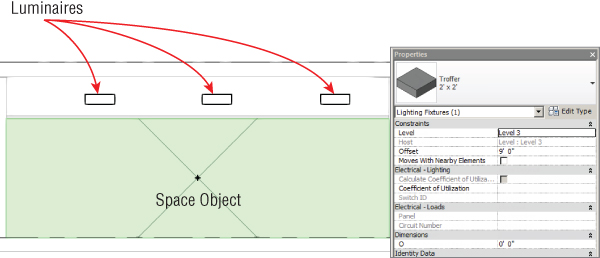
Figure 20.11 Fixtures outside the limits of a Space object
One way to remedy this is to use the Room Calculation Point that can be added to families such as light fixtures. This point allows you to associate a light fixture with a room or space even though the fixture is not within the bounds of the space. To add a Room Calculation Point to a light fixture family, check the option in the Family Category And Parameters dialog box as shown in Figure 20.12. The point can be located anywhere in the family by dragging it along either axis. The location is set in the family and cannot be modified in the project.
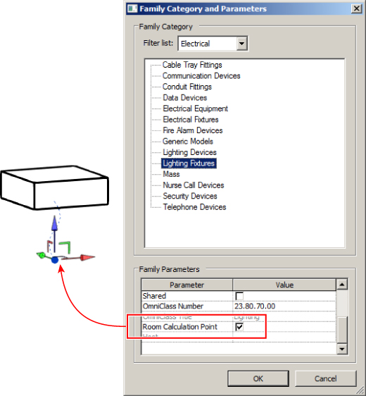
Figure 20.12 Room Calculation Point
This feature should be used with caution. It can result in incorrect lighting calculations because, though the fixtures can be associated with a space, the volume of the space may not be correct. Figure 20.13 shows light fixtures that are associated with a space because of the Room Calculation Point.
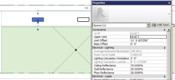
Figure 20.13 Light fixtures using the Room Calculation Point to associate with a space in a project
Another drawback to this feature is that the location of the Room Calculation Point cannot be modified in the project environment. You have to edit the family and reload it into the project in order to make a change.
Naming Conventions
A standard naming convention goes a long way in helping you maintain and manage your lighting fixture families. When you create a lighting fixture or modify an existing family, it is best to distinguish it from families that come installed with Revit MEP. This prevents the files from being overwritten if you update your library at the installation of a new release of the software.
A common practice is to prefix the family name with your initials or your company's acronym. This not only distinguishes the families as unique to you or your company, it also keeps them organized because they will all be listed together alphabetically.
The naming of IES files is also important to file management and organization. Most IES files that are provided by manufacturers are named with a convention that is unique to whoever is providing them. It can be difficult to determine the type of fixture that an IES file is associated with if the fixture is not named in a manner that indicates its type or performance. When you acquire an IES file, consider renaming it to indicate its characteristics so that those using the file can easily see what type of fixture it represents.
Performing Lighting Analysis
Your lighting fixture families require a light source if they are to be used for rendering or lighting calculations. A light source is a unique feature of a lighting fixture family that acts as the part that emits light. This does not necessarily mean a lightbulb, because you can define the shape of the light source according to how light is seen coming from the fixture. When you look at a light fixture that has a lens, the light appears to come from the shape of the lens.
You can also define the light distribution from the light source. Setting how the light is thrown from a fixture gives you a more accurate representation of the behavior of the fixture for lighting calculations and rendering. To give your family the exact photometric characteristics of a specified fixture, you can designate a photometric web file for the light source and also define settings such as color and intensity.
Lighting fixture families created from a light fixture template have one light source by default. It is possible to have a fixture family with multiple light sources, such as track lights or a chandelier. This requires creating a separate family that defines the light source, and then nesting it into your fixture family. The nested family must be shared in order to act as a light source. Shared nested families are actually loaded as individual families into the project as well as being seen as part of their host family. This means shared nested track lighting heads could be placed separately if desired as well as appear in a schedule separately as individual light fixtures or as part of the whole track and head lighting family. You can set a family to be shared by selecting the Shared box in the Family Category And Parameters dialog box, as shown in Figure 20.14.
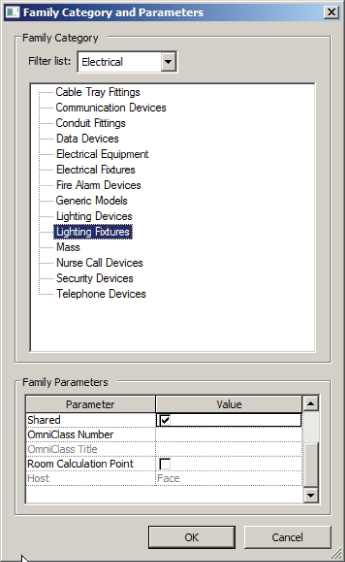
Figure 20.14 Selecting the Shared option in a family
Light Source Location
When starting with the Generic Model.rft template and categorizing the family as a light fixture with a light source, you will see the light source as a yellow object in the drawing area. The light source appears at the insertion point on the reference plane. You can move the light source to anywhere in 3D space within the family file. Figure 20.15 shows a light source and its type settings for a site light pole where the reference plane has been moved to the face of the fixture.
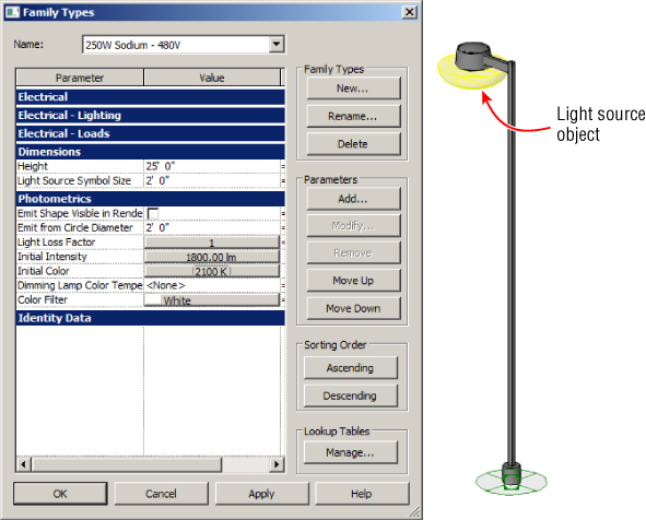
Figure 20.15 Light source and parameters of a pole light family
Depending on the light source definition settings you chose, you can change the size of the light source by editing the Light Source Symbol Size and Emit From Line Length parameters within the family. These parameters are not available if you are specifying a photometric web file.
Light source objects have axes that allow you to align and lock them to the fixture geometry or to a reference plane. If you place the light source inside solid geometry, you receive a warning that no light will be emitted when the family is in a rendered view. The light source can be located on the face of your fixture geometry, or it can be located within a void inside the geometry for a more realistic representation of the fixture. Figure 20.16 shows a down light family with a light source located inside the geometry of the fixture. The light distribution that appears to pass through the sides of the fixture will be blocked by the solid geometry when shown in a rendering. A material can be applied to the geometry to affect how the light will be reflected inside the fixture.
Figure 20.16 Light source inside fixture geometry
If you use the Lighting Fixture.rft template to create a family, you see an additional reference plane that defines the location of the light source. The light source object is locked to this plane and cannot be unlocked. The reference plane cannot be removed from the family. The location of this plane can be controlled parametrically to adjust the location of the light source if needed.
Light Source Definitions
You can define the shape of the light source and its distribution pattern by clicking the Light Source Definition button on the Lighting panel of the contextual tab that appears when you select the light source. You can choose from four shapes: point, line, rectangle, and circle. Combine any of these shapes with one of the four light distribution patterns located at the bottom of the Light Source Definition dialog box. Pattern options are spherical, hemispherical, spot, and photometric web (see Figure 20.17).
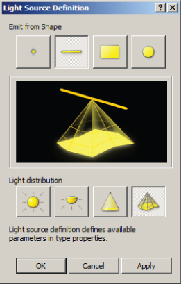
Figure 20.17 Light Source Definition dialog box
The light distribution patterns have different properties. The spherical and hemispherical distributions have the basic settings for size and photometric data, whereas the spot distribution has additional settings for the tilt angle and beam spread. The photometric web distribution has a parameter for tilt angle and one to define the light source by a photometric (IES) file. The properties of the light source distribution are all associated with type parameters of the fixture family. Figure 20.18 shows the properties of a light source with a spot distribution. Notice that the parameter values are mapped to family parameters (indicated by the = to the right side of the parameter value).
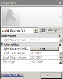
Figure 20.18 Light source properties
Light Source Parameters
The family parameters that control the properties of the light source are type parameters in the Photometrics parameter group. The parameters vary depending on the light distribution style chosen. These parameters have more to do with rendering appearances than with lighting calculations, because the IES file associated with a fixture drives the calculation values.
You can apply a light loss factor to the fixture family by clicking the button in the Light Loss Factor parameter cell. This opens a dialog box for choosing one of the two methods for applying a light loss factor. The Simple method allows you to use the slider in the dialog box to assign a total light loss factor to the family, whereas the Advanced method provides more specific options. You can input values for losses and depreciation manually or use the sliders. The combination of settings in the Advanced method generates a total, as shown in Figure 20.19.
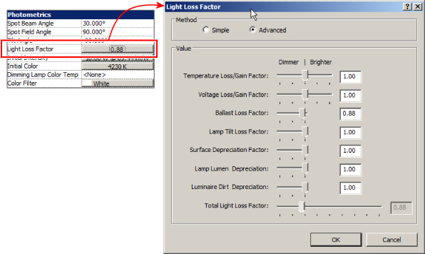
Figure 20.19 Advanced light loss factor settings
You can set the Initial Intensity parameter by any of the four values shown in the dialog box that appears when you click the button in the parameter cell. You can choose any of the value options to input. This information is often found in a lamp catalog or may be stored in the IES file associated with a fixture. You do not need to know the value for each option. When you input a value, the other options populate according to your input. Figure 20.20 shows an example in which an input was given for Luminous Flux and the other values populated accordingly.
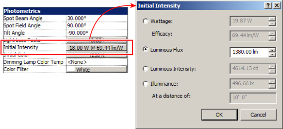
Figure 20.20 Initial Intensity dialog box values
Clicking the button in the Initial Color parameter cell opens a dialog box that lets you choose the color temperature of the light. The Color Preset drop-down offers settings that are based on various common lamp types and also offers the option to enter a custom color temperature value, as shown in Figure 20.21.
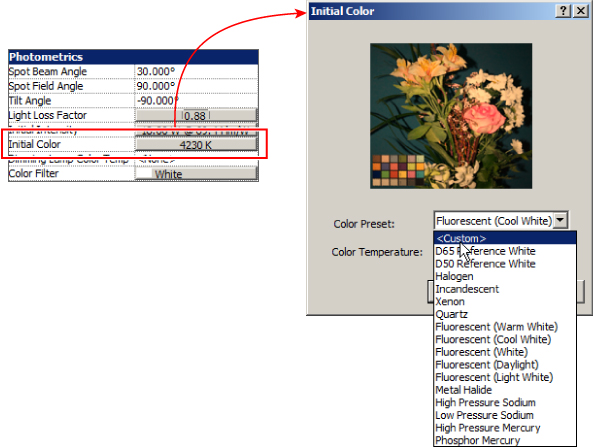
Figure 20.21 Initial Color dialog box
The Dimming Lamp Color Temperature Shift and Color Filter parameters are also for the appearance of the light from the fixture in renderings. You can apply a predefined lamp curve to affect the color and intensity of lights when they are dimmed. You can also apply a color filter to change how the light appears to be coming from the fixture.
Using Fixture Families as Intelligent Objects
Fixture families can do more than represent the geometry of the light fixtures used in your projects. You can add intelligence to your fixture families to make them useful for engineering and design decisions.
Using Parameters
As with any kind of family you create, the parameters you use provide the intelligence within your lighting fixture families, making them easily modifiable and useful for calculations.
Use family parameters to constrain the geometry of a fixture or to add data to it. Family parameters cannot be included in a schedule or tagged in views, so be sure to use them only for data that is not necessary to show on your construction documents.
As mentioned previously in this chapter, dimensions are good parameters to have in your fixture families. They allow you to customize a family to the exact dimensions of fixtures specified for your project without having to create an entirely new family. These dimension constraints are also useful for controlling the symbolic representation of fixtures, which is discussed later in this chapter.
Another useful parameter is one for electrical load. This gives you a parameter with which to associate the connector parameter so that when fixtures from different manufacturers are chosen, you can edit the family parameter and update the load of the connector.
Some types of lighting fixtures, such as site lighting fixtures, are available in different voltages that require a different number of poles for connection to a circuit. Having a parameter that defines the number of poles enables you to easily modify the connector by using parameter association. A fixture family with this parameter can have a type for 208V single-phase (two poles), 208V three-phase (three poles), or 277V single-phase, for example.
Adding Connectors
One feature of your lighting fixture families that makes them useful for the design of your projects is an electrical connector. Adding connectors to your families lets you connect them to electrical circuits in order to manage your panel loads and also lets you use wiring objects that maintain a connection to the fixtures when they are moved in the model.
The location of a connector in a lighting fixture family is not as important as on other types of electrical objects because the graphical representation of the wiring stops at the edge of the fixture. The easiest placement method for adding a connector is to choose the Face option. This places the connector in the center of whichever 3D face you select. Click the Electrical Connector button on the Connectors panel of the Create tab, and then choose the Face option on the Placement panel of the contextual tab that appears.
Next, choose the type of connector from the drop-down list on the Options Bar. You can change the type later by accessing the properties of the connector if needed. If you are using the connector to circuit your lights to a power panel, choose one of the power type connectors.
As you place your cursor over the fixture geometry, the 3D faces become highlighted, indicating where the connector can be placed. You can use the Tab key to cycle through available faces that have a common edge. Once you have highlighted the desired face, click to place the connector. There is no need to dimension or constrain the connector because it is always in the center of the selected 3D face.
If you want to control the location of a connector, you can use the Work Plane method of placement. This method requires that you select a plane on which to place the connector. You can use any named reference plane within the fixture family. Choosing the Work Plane option opens a dialog box with options for specifying the desired plane. You can pick the plane from a list or choose to select the plane manually. Figure 20.22 shows the dialog box and the various planes available in a sample lighting fixture family.
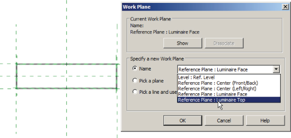
Figure 20.22 Work Plane connector placement dialog box
Once you have selected a plane for placement, the connector appears at the insertion point of the family. You can then move the connector by selecting it and using the Move command on the Modify | Connector Element contextual tab. It is important to use the Move command because attempting to click and drag the connector only rotates the orientation of the Connector object.
After you have moved the connector to the desired location, you can convert the temporary dimensions to actual dimensions to constrain the location of the connector if necessary.
The properties of a connector determine how the fixture family behaves electrically. The parameters of a connector can be associated with parameters of the fixture family so that they can be changed parametrically in a project or be given different values for different types within the family. For example, you can have a fixture family with multiple voltage options. The Voltage parameter of the connector can be associated with the Voltage parameter of the family by clicking the small square to the far right of the connector's Voltage parameter. This opens a dialog box that allows you to choose the family parameter to which you can associate the connector parameter. Only family parameters that match the discipline and type are available, so you cannot associate a Voltage parameter with something that is not a voltage.
It can be helpful to associate the Load Classification parameter of a connector to a family parameter for load classification. This lets you easily change the classification and demand factor of a fixture family to suit the specific needs of a project, without having to edit the fixture family.
Representing Light Fixtures on Construction Documents
As with most parts of an electrical design, a lighting plan can be represented symbolically. There is no real need to show the actual fixtures in the model on construction documents. Using symbolic lines and symbols to show lighting fixture locations enables you to represent fixtures that are alike with a common symbol. This reduces the number of symbols required, simplifying your construction documents. For example, although your project may have several types of 2×4 recessed fixtures, they can all be represented with the same symbol in your plan views.
Using symbolic lines and symbols also helps improve the performance of your Revit model. 2D graphics can be more easily processed and regenerated than 3D graphics. Although it is recommended that you model your light fixtures in the simplest form possible, you may receive fixture families from manufacturers or other sources that are modeled at a more complex level. Having many light fixtures in a project and showing their 3D graphics can significantly affect how well your model performs.
Another reason for using symbolic lines or nested annotation symbols in your lighting fixture families is that it gives you another level of visibility control for your fixtures. Through your use of parameters, a light fixture can display different configurations of symbolic lines based on variations within the fixture without you having to create another family or family type.
A good example of a light fixture using a nested annotation symbol is an exit light. These fixtures are commonly shown on construction documents as a symbol, instead of the actual light fixture showing. However, the symbol may be shown in different configurations, depending on the number of faces or direction arrows that are on the fixture. Figure 20.23 shows an exit light family in both plan and 3D views. Notice that a symbol is used to represent the fixture in ceiling plan view and that a filled region within the symbol indicates the location of the face of the fixture.
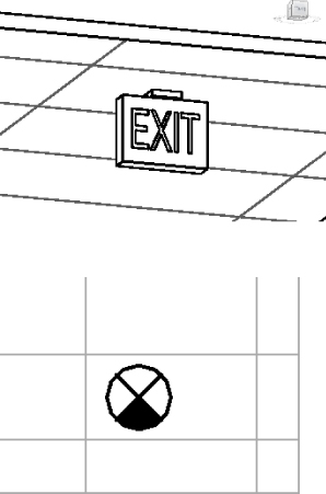
Figure 20.23 Exit lighting fixture in plan and 3D views
Creating this type of functionality is easily achieved by using a nested annotation family in the lighting fixture family. The annotation family contains lines and filled regions whose visibility is controlled by Yes/No parameters.
To create an exit light family with multiple display options, do the following:
- Open the RMEP2016_
Ch20_Exit Light Annotation.rfafamily found at this book's web page,www.sybex.com/go/masteringrevitmep2016. - Draw a circle with the center point at the intersection of the reference planes. The radius of the circle should be small (approximately 3⁄32″ or 2.5 mm) so that the annotation is the correct size at different view scales.
- Draw a line from one quadrant of the circle to the opposite quadrant. Rotate the line 45 degrees, using the center of the circle as the axis, and mirror the line by using one of the reference planes as the axis, creating four equal quadrants within the circle.
- Create a filled region by tracing over the top quadrant. Use invisible lines for the border of the filled region and Solid Fill for the pattern. Click the green check mark button on the contextual tab to finish creating the filled region, as shown in Figure 20.24.
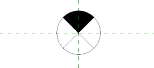
Figure 20.24 Filled region
- Mirror the filled region by using the reference plane perpendicular to the region as the axis to create another filled region directly opposite the first region.
- Click the Family Types button on the Properties panel of the Create tab. Create a new parameter by clicking the Add button to the right of the dialog box. Name the parameter FACE1. Set the parameter as an instance parameter, and set Type Of Parameter to Yes/No. Click OK.
- Repeat step 6 to create another parameter named FACE2. Click OK to exit the Family Types dialog box.
- Select one of the filled regions. Click the small box to the far right of the Visible parameter in the Properties palette. Select FACE1 from the list and click OK, as shown in Figure 20.25. Select the other filled region and repeat, choosing FACE2 from the list. Save and exit the family.
4
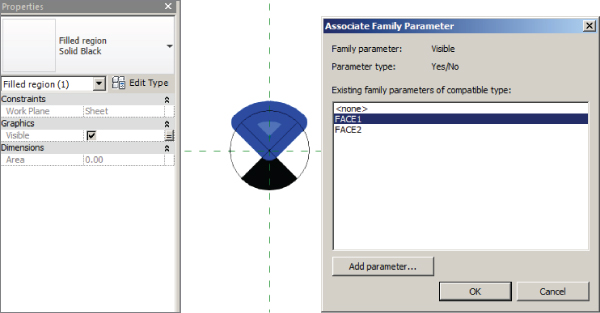
Figure 20.25 Linking parameter to visibility
- Open the RMEP2016_
Ch20_Ceiling Exit Light.rfafamily found at this book's web page. - Using the reference planes provided, create a 4″ (100 mm) square extrusion centered at the intersection of the reference planes. Set the depth of the extrusion to 1″ (25 mm). Create another extrusion that is 2 1/2″ (60 mm) wide and 12″ (300 mm) long. In the Properties palette, set Extrusion Start to 1″ (25 mm) and Extrusion End to 11″
- (275 mm), as shown in Figure 20.26.
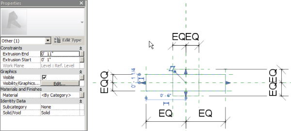
Figure 20.26 Creating family geometry
- Select both extrusions, and click the Visibility Settings button on the Mode panel of the contextual tab. Remove the check mark from the box next to Plan/RCP and click OK. This keeps the extrusions from being visible in plan views or reflected ceiling plans.
- Click the Family Types button on the Properties panel of the Create tab. Create a new parameter by clicking the Add button at the right of the dialog box. Name the parameter Show Face 1. Set the parameter as an instance parameter, and set Type Of Parameter to Yes/No. Group the parameter under Graphics. Click OK.
- Repeat step 12 to create another parameter named Show Face 2. Click OK to exit the Family Types dialog box.
- Click the Load Family button on the Insert tab. Browse to the annotation family you created and click Open. Click the Symbol button on the Annotate tab, and place the annotation symbol at the intersection of the reference planes.
- Select the annotation symbol, and click the small box to the far right of the FACE1 parameter in the Properties palette. Choose Show Face 1 from the list and click OK. Repeat for the FACE2 parameter, choosing Show Face 2 from the list. Save and exit the family.
- Open the RMEP2016_
Ch20_SampleProject.rvtfile found at this book's web page. - Open the 1 – Ceiling Elec view, and click the Load Family button on the Insert tab. Browse to the newly created exit light fixture family and click Open. Click the Lighting Fixture button on the Create tab. Select the Place On Face option from the contextual tab, and place the fixture on the ceiling. It is notable that only the annotation symbol is displayed and not the extrusion graphics.
- Click the light fixture, and deselect the box for the Show Face 2 parameter in the Properties palette. Notice that the filled region for FACE2 is no longer displayed.
Not all light fixtures are represented by an annotation symbol. Some fixtures need to be shown at their actual size for coordination purposes. If a nested annotation is used for these types of fixtures, the annotation always remains the same size on the printed sheet, while the building is scaled in relation to that same sheet. Symbolic lines can be used in a fixture family to represent the outline of a fixture without having to show the model graphics within the family.
Symbolic lines appear in any view that is parallel to the view in which they are created. When you're adding symbolic lines to a lighting fixture family, they need to be drawn in the Ref. Level Floor Plan view or Ref. Level Ceiling Plan view for ceiling-mounted fixtures. If the fixture you are creating is wall mounted, draw the symbolic lines in either the Front or Back elevation view.
Symbolic lines do not change size in different scale views, so they can be drawn to match the size of the fixture. You can constrain symbolic lines to reference planes or model graphics so that they move when the fixture is changed.
When working in a lighting fixture family, any symbolic lines belong to the Lighting Fixtures subcategory by default. You can create a unique subcategory for the lines to allow for greater visibility control within the model.
If your lighting family is to be placed on a sloped ceiling and you are using symbolic representation, you need to create them as model lines with their own subcategory. Figure 20.27 shows two light fixture types, A and B, placed on level and sloped ceilings. Type A has model lines, whereas type B uses symbolic lines to reflect the symbolic representation. In planning a type of family like type B, consider that the symbolic representation requires a subcategory such as Lighting Fixture – Symbol.
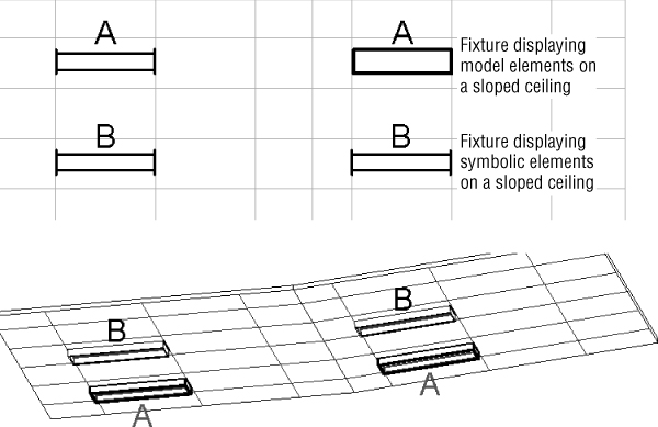
Figure 20.27 Light fixtures with symbolic/model lines
Although this does mean that view templates have to be adjusted carefully to take into account the symbolic and model elements of the family, you can use the same light family in both level and sloped ceilings and retain your graphical standards.
Although you can draw symbolic lines in a lighting fixture family, you cannot create a filled region. Filled regions are useful for showing a portion of the fixture filled in to denote an emergency lighting fixture. If you create a filled region in an annotation family and then nest that annotation into a fixture family, the annotation cannot be resized to match the fixture if its dimensions change. However, you can use a detail component family instead.
You can create a detail component family with parameters for length and width. A filled region can be drawn in the detail component family that is constrained to the parameters. When nested into a lighting fixture family, the parameters of the detail component can be associated with the parameters within the fixture family so that the detail component will match the size of the fixture. Figure 20.28 shows a detail component family designed to indicate when a lighting fixture is an emergency type.
Figure 20.28 Detail component family for an emergency lighting fixture
With the detail component nested into the fixture family, its visibility can be associated with a Yes/No parameter so that it can be turned on or off as desired. This should be an instance parameter so that the same fixture type can be shown as normal or as emergency. Figure 20.29 shows two instances of a light fixture, one of which has been set to an emergency light.
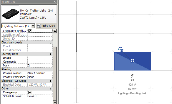
Figure 20.29 Lighting fixture family with a detail component for emergency lighting display
Detail components can be more useful than annotation symbols because they can be placed easily into an elevation view within a fixture family, whereas annotation symbols require extra steps and management. When you create a wall-mounted fixture that is face hosted, the Front or Back elevation view is what you will see when the fixture is hosted by a vertical face, so any symbolic representation must be placed in the Front or Back elevation view of the family.
The Bottom Line
- Create different types of lighting fixture families. Many types of lighting fixtures are required for various applications within a building. With Revit MEP, you can create any type of lighting fixture and include any data associated with that fixture.
- Master It Knowing how a lighting fixture will be used in a Revit model is important for determining the kind of fixture family to create. True or false: A nonhosted light fixture family cannot be associated to a work plane.
- Use a light source in your lighting fixture families. Lighting fixtures can be used in making design decisions because they not only represent the fixture as a 3D or 2D object, they also contain photometric data from real-world lighting fixtures for use in lighting analysis.
- Master It Photometric web files can be obtained from lighting fixture manufacturers. These files provide the lighting distribution characteristics of a fixture when added to a family. How can you be sure that the IES file you are using is appropriate for the type of fixture in which it is being used?
- Create and manage fixture types and parameters. The parameters of a lighting fixture family are what make it an intelligent object. They can be used to create multiple types within the same family or to manage the electrical characteristics of a fixture.
- Master It Connectors allow for and determine the electrical properties of a lighting fixture family. Describe the process of ensuring that a connector has the same load and voltage values that have been assigned to the fixture.
- Use lines and symbols to represent lighting fixtures. Some lighting fixtures are shown on construction documents as symbols, whereas others are shown as their actual size. Symbolic lines or annotation symbols can be used to simplify or even eliminate the need to display model graphics.
- Master It Annotation symbols nested into lighting fixture families can represent the fixture without having to show the model graphics. Is it possible to use a nested annotation family to represent a wall-mounted fixture in a face-hosted lighting fixture family? Explain.