14
Working with Coordinate Spaces
Understanding the different coordinate spaces used in graphics rendering is a critical and transferable skill that you as a programmer require. These are a universal concept across all graphics and game engines, and being able to apply them to manipulate a virtual scene is a skill you’ll never regret acquiring.
These key matrices form the OpenGL matrix stack that defines all mathematical operations. Mathematical operations are required to take the vertices of a model from their own local coordinate system into a pixel on the computer screen. They define not only where individual objects are in a scene and how they are scaled and rotated, but also allow for the creation of a virtual camera. This camera can be moved and orientated to influence the location and orientation from which a scene is viewed.
The modelview, view, and projection matrices contain indispensable mathematical functions for any graphics engine. You’ve been exploring these mathematical concepts throughout this book. Think of this chapter as a culmination of all the mathematical content you’ve explored thus far.
In this chapter, we will cover the following topics:
- Understanding OpenGL’s Matrix Stack
- Working with the Modelview Matrix
- Working with the View Matrix
- Working with the Projection Matrix
By the end of this chapter, you will have developed the skills to create, manipulate, and apply the matrix stack in 2D and 3D spaces as well as validate the results of the mathematics you are using to develop more robust code and graphics applications.
Technical requirements
In this chapter, we will be using Python, PyCharm, and Pygame, as used in previous chapters.
Before you begin coding, create a new Chapter_14 folder in the PyCharm project for the contents of this chapter.
The solution files containing the code can be found on GitHub at https://github.com/PacktPublishing/Mathematics-for-Game-Programming-and-Computer-Graphics/tree/main/Chapter14.
Understanding OpenGL’s Matrix Stack
In graphics, the current transformation applied to a point or object is determined by the current model-view-projection (MVP) matrix. This is a culmination of the model matrix, the view matrix, and the projection matrix. We first discussed these matrices as coordinate spaces in Chapter 4, Graphics and Game Engine Components. Each one has a specific use in the graphics pipeline, as is shown in Figure 14.1 (this diagram has been reinserted here from Chapter 4, Graphics and Game Engine Components, for your convenience):

Figure 14.1: The graphics pipeline
The coordinates or points that define a graphics object are stored in a model’s local coordinate system. They define the geometry of the object independently of where it is situated in world space. As we saw in Chapter 4, Graphics and Game Engine Components, a cube can be defined by six points, one for each of the vertices, thus:
cube.vertices = [(0.5, -0.5, 0.5),
                 (-0.5, -0.5, 0.5),
                 (0.5, 0.5, 0.5),
                 (-0.5, 0.5, 0.5),
                 (0.5, 0.5, -0.5),
                 (-0.5, 0.5, -0.5)
                ]
These values tell us nothing about where the cube is located in the world, but just the structure of it as it was created. When the cube is placed in the world, transformations are applied that define its location, scale, and orientation. These transformations (accumulated in the modelview) change the values of the vertices so that they can be drawn by the graphics API in the correct location. However, while this process positions the cube in the 3D world (or 2D world if you aren’t working with a z axis), it doesn’t define what the value of each vertex is with respect to the camera viewing it. So, the points undergo another operation that projects them into camera space. Last but not least, the points in camera space need to become pixels on the screen, and therefore they undergo another operation that projects them onto a 2D plane that represents the computer screen.
We could, in fact, say that a rendered cube has four sets of coordinates: one in model space, one in world space, one in eye (or camera) space, and one in screen space. What these coordinates are in each space depends on how the cube sits with respect to the space’s origin. This is illustrated in Figure 14.2:

Figure 14.2: Coordinate spaces
When we work in games and graphics, the majority of the operations performed are in world space as it is this virtual world we create and want to position objects within. When you translate, scale, or rotate an object, it is this space you are working in. However, at some point, the vertices of a model end up being converted into each of these spaces to get the final pixels on the screen. Mathematically the entire process that draws a coordinate ,Q, on the screen from an original point, P, looks like this:
Q = projection matrix * view matrix * model matrix * PThe model matrix puts the point into world space, the view matrix then places it in eye space, and then the projection matrix converts it into screen coordinates. Notice how the operation works entirely on multiplication? This is what makes these matrices so efficient, as we discussed in Chapter 13, Understanding the Importance of Matrices. We will now look at each of the matrices that comprise the OpenGL matrix stack in turn to gain a greater insight into their purpose.
Working with the Model Matrix
The model matrix is the accumulation of the multiplications of the transformation matrices that are to be applied to a point or vector. As we discovered in Chapter 13, Understanding the Importance of Matrices, the order in which the transformations are multiplied is important to the final outcome. Also, at the end of the same chapter, you discovered that in OpenGL, you can obtain the contents of the modelview matrix with the following code:
glGetDoublev(GL_MODELVIEW_MATRIX)
Rather than using OpenGL’s own methods for moving, resizing, and orienting an object, you can set the matrix manually, and then perform matrix multiplication to apply the transformation to a model as long as you keep in mind the format of the modelview matrix.
These transformations were performed in Chapter 13, Understanding the Importance of Matrices:
glTranslatef(0, 0, -3)
glRotated(45, 1, 0, 0)
glScalef(0.5, 2, 1)
The result of performing these transformations was a printout of this modelview matrix:
[[ 0.5         0.          0.          0.        ]
 [ 0.          1.41421354  1.41421354  0.        ]
 [ 0.         -0.70710677  0.70710677  0.        ]
 [ 0.          0.         -3.          1.        ]]
If you take notice of where the resulting values end up in the matrix, you can see that the
0. 0. -3. values are the translation values. This is because the 4x4 translation matrix stores its values in the last column (or row, depending on which way around you have the matrix). The 1.41421354 1.41421354 and -0.70710677 0.70710677 values are an accumulation of the rotation and scaling operations, and 0.5 is the x scaling factor. When you multiply translations, rotations, and scalings together, you can always determine the values of the translation from the resulting matrix because of their location, whereas the values for the scaling and rotation will always be mixed together. So, it is impossible to tell what the original rotations or scalings were. It’s rare that you would want to set the modelview matrix by hand, as it’s much easier to calculate it.
Let’s give it a go for ourselves.
Let’s do it…
In this practical exercise, you will replace the OpenGL methods for translation, scaling, and rotation with your own calculations. Follow these steps:
- Create a new Python folder called Chapter_14 and copy the contents from Chapter_13 into it.
- We are going to rewrite the entire contents of the Transform.py class to work with matrices. Delete all the lines of code in your Transform.py class and add the following code:
import pygame
import math
import numpy as np
class Transform:
def __init__(self):self.MVM = np.identity(4)def get_MVM(self):return self.MVM
To begin, the initialization method has had the original variables removed and self.MVM has been added to store the modelview matrix. It is initially set to an empty identity matrix. When we zero a matrix in computer graphics, it’s not set to all values of zero; otherwise, any other matrix multiplied with it will result in another matrix full of zeros.
Following this, a new method for returning the modelview matrix has been added.
- The next method that you add here will update the position of the object. It does this through a multiplication operation of the existing modelview matrix with a translation matrix:
def update_position(self, position):self.MVM = self.MVM @ np.matrix([[1, 0, 0, 0],[0, 1, 0, 0],[0, 0, 1, 0],[position.x, position.y,position.z, 1]])
The update_scale() method is similar to the update_position() method in that it performs a matrix calculation. But notice the format of the matrix is different to cater to scaling operations:
    def update_scale(self, amount: pygame.Vector3):
        self.MVM = self.MVM @ np.matrix([
            [amount.x, 0, 0, 0],
            [0, amount.y, 0, 0],
            [0, 0, amount.z, 0],
            [0, 0, 0, 1]
])- The final three methods you will add are all for rotation. They allow you to rotate around any axis:
def rotate_x(self, amount):amount = math.radians(amount)self.MVM = self.MVM @ np.matrix([[1, 0, 0, 0],[0, math.cos(amount),math.sin(amount), 0],[0, -math.sin(amount),math.cos(amount), 0],[0, 0, 0, 1]])def rotate_y(self, amount):amount = math.radians(amount)self.MVM = self.MVM @ np.matrix([[math.cos(amount), 0,-math.sin(amount), 0],[0, 1, 0, 0],[math.sin(amount), 0,math.cos(amount), 0],[0, 0, 0, 1]])def rotate_z(self, amount):amount = math.radians(amount)self.MVM = self.MVM @ np.matrix([[math.cos(amount), math.sin(amount),0, 0],[-math.sin(amount), math.cos(amount),0, 0],[0, 0, 1, 0],[0, 0, 0, 1]])
Take note of how the three rotation matrices have been formatted for the different axes.
- To use the modelview matrix to set the transformation of the object, the code in Object.py needs to be updated thus:
..
def update(self, events = None):
glPushMatrix()for c in self.components:if isinstance(c, Transform):glLoadMatrixf(c.get_MVM())mv = glGetDoublev(GL_MODELVIEW_MATRIX)print(“MV: “)print(mv)elif isinstance(c, Mesh3D):glColor(1, 1, 1)..
Take note here of how the OpenGL transformations have been removed and replaced with a glLoadMatrixf() call instead. This method loads in the matrix calculated by the Transform class. The printing of the modelview matrix has been left to show you the contents of the matrix after we have calculated it manually. The idea is that if you perform the exact same transformations as we did in Chapter 13, Understanding the Importance of Matrices, the modelview matrix will be the same.
- To use these modifications, open up TransformationMatrices.py and modify how the cube is being drawn thus:
..
objects_3d = []
objects_2d = []
cube = Object(“Cube”)
cube.add_component(Transform())
cube.add_component(Cube(GL_POLYGON, “images/wall.tif”))
trans: Transform = cube.get_component(Transform)
trans.update_position(pygame.Vector3(0, 0, -3))
trans.rotate_x(45)
trans.update_scale(pygame.Vector3(0.5, 2, 1))
objects_3d.append(cube)
clock = pygame.time.Clock()
..
In these changes, the Transform component being added to the cube no longer has any parameters passed to it, and the position, rotation, and scaling code has changed to the new methods we just created in Transform.py. The values being used are identical to the ones that we used previously in Chapter 13, Understanding the Importance of Matrices.
At this point, you can run TransformationMatrices.py and take a look at the modelview matrix that prints out in the console. Is it the same as the one that OpenGL created in Chapter 13, Understanding the Importance of Matrices? It shouldn’t be, as I intentionally had you put this code in to point out something. Note that there won’t be anything visible in the window; it will just be black.
Take some time now that you have this code working to ponder my last question before you continue reading.
At the beginning of this chapter, I reminded you that the order of transformations matters. Although you may have the position, rotation, and scaling happening in the same order as the previous OpenGL methods used, now that we are calculating them, we need to reverse the order around.
As OpenGL is given each matrix to apply, it places it on a matrix stack. You can imagine this as a tower being constructed where each matrix is a brick placed on top of the previous one. The last matrix added is the topmost one. To process these matrices, OpenGL multiplies them together, starting at the top of the stack and working down. In fact, OpenGL maintains a matrix stack for both the modelview and projection modes and another one for textures. When a command such as glTranslate() is run, a matrix is pushed onto the stack. Whatever is in the stack at the time of drawing a frame gets applied to the geometry of the objects in the scene. When a glLoadIdentity() call is made, OpenGL is essentially zeroing or reinitializing the stack. When the vertices of an object are processed through the stack, the multiplication equation for all matrices is constructed from the bottom of the stack upward. For example, if we perform a translation, a rotation, and then a scale using OpenGL methods, the translation goes on the stack first, followed by the rotation, and then the scale on the top. Reading this in reverse order to construct the multiplication gives the following:
scale * rotation * translation
The order these operations take place is from right to left. Therefore, translation is multiplied by rotation, and then the result is multiplied by scale. In our code, if you take a look at our matrix multiplication, we are already applying the transformation matrix on the right of the operation and, as such, achieve a different order. Again, if you are ever in doubt if your code is working as it should, double-check it via different calculation methods including using online calculators.
Having the transformation of an object in a neat matrix is a nice feature, but there will come times, for example, when you are animating, when you need to obtain the current position, rotation, and scale of an object. As we have already discussed, finding the translation or position of an object is achieved by extracting the last column of the matrix. But how do we find rotation and scaling? Let's start with the transformation matrix:

The position in this matrix is the (d, h, l) vector.
The scale is the length of the first three column vectors, such that the x scale is the length of (a, e, i), the y scale is the length of (b, f, j), and the z scale is the length of (c, g, k). We can use Pythagoras’ theorem, as discussed in Chapter 9, Practicing Vector Essentials, to calculate these lengths.
The rotation matrix is what remains after the scaling and translations are taken out. So, for each column, the values are divided by their respective scale, like this:

I’ll leave the implementation of this as an exercise for you to work on by yourself before continuing.
Your turn…
Exercise A. Create three new methods in the Transform class called get_position(), get_scale(), and get_rotation() that return the values associated with each by extracting them from the modelview matrix.
In this section, we have examined the modelview matrix and recreated and applied it in our OpenGL project. You might be asking yourself why we would bother with such intricacies when there are OpenGL API methods that allow us to interact with the modelview matrix in a much simpler way. The answer is twofold. First, it is important that you understand the nature and construction of the modelview matrix to take your object manipulation skills to the next level, and second, you should possess the skills to program your own modelview matrix in the event you find yourself in a situation where such OpenGL methods aren’t available.
One such situation is in transitioning from the version of OpenGL we are using in this book to the vertex/fragment shader methods implemented in OpenGL 3.x, which no longer uses the glTranslate, glRotate, and glScale methods. However, at this stage, it is critical for your learning journey that you have an appreciation of these methods and their equivalent matrix operations before transitioning to vertex/fragment shader modeling in later chapters.
With knowledge of the modelview matrix in your graphics toolkit, it’s now time to examine the view matrix.
Working with the View Matrix
The view matrix takes the world space coordinates produced by the modelview matrix and transforms them into the camera or eye space. The eye space assumes the origin of this space to be at the position of the camera or viewer’s eye. As we saw in Chapter 4, Graphics and Game Engine Components, the eye space can either be a frustum (a pyramid with the top cut off for perspective views) or orthogonal (a rectangular prism for parallel views). The view matrix can take translation and rotations like the modelview matrix, but instead of transforming individual objects, it transforms everything in the world. That’s because it’s basically the equivalent of moving a camera around in the world, and then determining what the world will look like through that camera.
Unlike the modelview matrix, which can be loaded after an OpenGL call to glGetDoublev( GL_MODELVIEW_MATRIX), the view matrix sets a special matrix mode. The view matrix is multiplied with the modelview matrix, and then the resulting combined matrix is applied to any geometry in the environment. This geometry is made up of all the points representing any vertices of meshes present in the 3D scene.
The easiest way to see how this works is to implement a Camera class in our project that will allow us to move a camera around in the scene.
Let’s do it…
In this exercise, we will create a Camera class that can maintain the location of the camera viewing the world as well as enable it to move around the scene. Follow these steps:
- Create a new Python script called Camera.py and add the following code to it:
import pygame
import math
import numpy as np
class Camera:
def __init__(self):self.VM = np.identity(4)def get_VM(self):return self.VM
The Camera class maintains a 4x4 matrix that is initialized to an identity matrix. This places the camera at (0, 0, 0) in the world and has it facing down the positive direction along the z axis. The class also provides a way of returning this matrix with the get_VM() method to return the view matrix for use elsewhere in the project.
The get_position() and update_position() methods work together in the same way they did for the Transform class:
    def get_position(self):
        position = pygame.Vector3(self.VM[0, 3],
                                  self.VM[1, 3],
                                  self.VM[2, 3])
        return position
    def update_position(self, position:
                        pygame.Vector3):
        self.VM = self.VM @ np.matrix([[1, 0, 0, 0],
                                       [0, 1, 0, 0],
                                       [0, 0, 1, 0],
                                       [position.x,
                                        position.y,
                                        position.z,
                                        1]])
The get_position() method returns the position of the camera from the final row in the view matrix, and this is used by the update_position() method to update the camera’s position by translating it by the vector value passed through. The position is stored in the view matrix.
- To update the position of the camera, we are adding a very simple update() method that we can call from our main program to allow forward and backward movement of the camera along the z axis with the W and S keys:
def update(self):key = pygame.key.get_pressed()if key[pygame.K_w]:self.update_position(self.get_position() +pygame.Vector3(0, 0,0.01))if key[pygame.K_s]:self.update_position(self.get_position() +pygame.Vector3(0, 0,-0.01)) - In TransformationMatrices.py, instantiate the camera thus:
from OpenGL.GLU import *
from Cube import *
from Camera import *
..
trans.update_scale(pygame.Vector3(0.5, 2, 1))
trans.rotate_x(45)
trans.update_position(pygame.Vector3(0, 0, -3))
camera = Camera()
objects_3d.append(cube)
clock = pygame.time.Clock()
..
- Inside the while loop in TransformationMatrices.py, add a line to call the camera’s update, and then pass the camera to the object update, like this:
while not done:
events = pygame.event.get()..glPushMatrix()glClear(GL_COLOR_BUFFER_BIT | GL_DEPTH_BUFFER_BIT)camera.update()set_3d()for o in objects_3d:o.update(camera, events)set_2d()..
- Finally, in Object.py, you can modify the update() method to multiply the modelview matrix with the camera’s view matrix to allow the camera’s movement to modify the way the scene is viewed thus:
..
from Camera import *
..
def update(self, camera: Camera, events = None):
glPushMatrix()for c in self.components:if isinstance(c, Transform):glLoadMatrixf(c.get_MVM() *camera.get_VM())#mv = glGetDoublev(GL_MODELVIEW_MATRIX)#print(“MV: “)#print(mv)
Note that at this point, you can remove or comment out the lines printing the modelview matrix unless, of course, you are interested in what it contains.
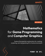
- Run TransformationMatrices.py. You will now be able to move the camera using the w key to move toward the cube and the s key to move away. Without modifying the transform that belongs to the cube, the scene can be changed to allow for the camera’s viewing location, as shown in Figure 14.3:
Figure 14.3: Moving toward and away from the cube
In this exercise, we started creating a Camera class to allow for the movement of the camera around the world. Currently, it only moves forward and backward; however, we will expand on this in Chapter 15, Navigating the View Space, to allow sideways movement and rotations.
In this section, we have investigated the view matrix. As it gets blended with the modelview matrix in the same step, it might seem like a superfluous operation. However, the modelview matrix is one that each graphics object maintains as its individual transform, whereas the view matrix is influenced by camera movement and applied to all objects in the world.
The final matrix we need to examine to complete our discussion on the OpenGL matrix stack is the projection matrix.
Working with the Projection Matrix
The objective of the projection matrix is to take objects from view space into projection space. Basically, this takes coordinates inside the camera’s viewing volume (specified by the shape and size of the frustum or rectangular prism) and puts them in normalized device coordinates (NDCs). The calculations for a perspective view’s projection matrix were explained in Chapter 4, Graphics and Game Engine Components. The OpenGL documentation also specifies how it constructs the projection matrix with a call to gluPerspective() at registry.khronos.org/OpenGL-Refpages/gl2.1/xhtml/gluPerspective.xml where the mathematics is revealed. The projection matrix is defined as follows:

Here, the values of a, b, c, and d are calculated from the parameters passed to gluPerspective(), which are the vertical field of view (fovy), the aspect ratio of the window, the near plane, and the far plane. These values are determined thus:
f = cotangent(fovy/2) = 1/tan(fovy/2)
a = f/aspect ratio
b = f
c = (far + near)/(near – far)
d = (2 * near * far) /(near – far)
From the positions in the matrix of the calculations for a, b, c, and d, you can see that a, b, and c are scaling values for the x, y, and z dimensions respectively, and d is the z-axis offset. Take a look at the calculations for each of these, and you will be able to determine whether this makes sense, as you are wanting to take the world’s camera view and rescale and move it into NDC coordinates.
OpenGL sets the projection matrix when in GL_PROJECTION matrix mode, and in our project, we’ve used the gluOrtho2D() method to set a parallel projection and the gluPerspective() method to set a perspective projection. Both of these can be examined in the set_2D() and set_3d() methods in our project. As with glTranslate() and other transformation methods, these projection matrix creation methods are also obsolete in OpenGL 3.x, and therefore it’s worth examining these in detail here.
Let’s now replace the call to gluPerspective() in our project with a projection matrix we construct.
Let’s do it…
In this exercise, we will use the Camera class to store its own projection matrix that can be used in the GL_PROJECTION_MATRIX mode. Follow these steps:
- Modify the Camera class to include the calculations to create a projection matrix, like this:
class Camera:
def __init__(self, fovy, aspect, near, far):f = 1/math.tan(math.radians(fovy/2))a = f/aspectb = fc = (far + near) / (near - far)d = 2 * near * far / (near - far)self.PPM = np.matrix([[a, 0, 0, 0],[0, b, 0, 0],[0, 0, c, -1],[0, 0, d, 0]])self.VM = np.identity(4)def get_VM(self):return self.VMdef get_PPM(self):return self.PPM
Here, we are defining a perspective projection matrix (PPM). The calculations for each component of the matrix are taken from the OpenGL definition for gluPerspective(). Note the positions of d and -1 in the matrix are swapped to give the inverted matrix because of the way we are multiplying them at the end of the PPM instead of in front. A method called get_PPM() has been added to return the matrix for use in the main program. Here, you should also note how we will be accepting the fovy value in degrees as does the gluPerspective() method, but because of the math functions in Python, we need to ensure these degrees are converted to radians before any calculations are performed.
- In the TransformationMatrices.py script, modify the creation of the camera to the following:
..
trans.rotate_x(45)
trans.update_position(pygame.Vector3(0, 0, -3))
camera = Camera(60, (screen_width / screen_height),
0.1,1000.0)objects_3d.append(cube)
clock = pygame.time.Clock()
..
- Still in the TransformationMatrices.py script, in the set_3d() method, use the camera’s projection matrix to set the projection mode instead of gluPerspective(), like this:
def set_3d():
glMatrixMode(GL_PROJECTION)glLoadMatrixf(camera.get_PPM())#glLoadIdentity()#gluPerspective(60, (screen_width /# screen_height), 0.1,# 1000.0)pv = glGetDoublev(GL_PROJECTION_MATRIX)print(“PV: “)print(pv)glMatrixMode(GL_MODELVIEW)glLoadIdentity()..
Note that I have also included code to print out the projection matrix so that you can compare the results of both techniques if you are interested.
- Run the project. Changing to the use of our own projection matrix will not change how your project runs, and you will still be able to move the camera with the w and s keys.
In this exercise, we’ve given the world camera a projection matrix that deals with the perspective projection of objects in the world. In the project, we also have a 2D view with a parallel camera controlled by a call to the gluOrtho2D() method. Just as gluPerspective() has an associated matrix, so does gluOrtho2D(). The next challenge for you is to implement this.
Your turn…
Exercise B. In your Python project, create a Camera2D class that stores a parallel projection matrix. Use the matrix you create in the new Camera2D class to replace the call to gluOrtho2D() in the set_2d() method in your main program. The documentation for gluOrtho2D() can be found at https://registry.khronos.org/OpenGL-Refpages/gl2.1/xhtml/gluOrtho2D.xml. You will also require the documentation for glOrtho(), which can be found here: https://registry.khronos.org/OpenGL-Refpages/gl2.1/xhtml/glOrtho.xml.
The projection matrix is the final piece of the puzzle when converting model coordinates into screen coordinates. Together with the modelview matrix and the view matrix, they contain all the transformational information to render a vertex in the correct position on a computer screen.
Summary
In this chapter, we have explored the principal modelview, view, and projection matrices that comprise the OpenGL matrix stack. As discussed, these matrices are key to understanding how model coordinates are transformed into screen positions for the rendering of objects. No matter which graphics engine you work with, these matrices are always present. As you move into vertex/fragment shading, it is key that you understand the role each of these matrices plays, and the order they are applied to model coordinates.
In the next chapter, we will work further to improve the maneuverability of the camera that we created herein by adding advanced movement and rotational abilities. This will allow you to fly the camera through the scene and orient it for viewing from any angle.
Answers
Exercise A.
def get_position(self):
    position = pygame.Vector3(self.MVM[0, 3],
                              self.MVM[1, 3],
                              self.MVM[2, 3])
    return position
def get_scale(self):
    sx = pygame.Vector3(self.MVM[0, 0], self.MVM[1, 0],
                        self.MVM[2, 0])
    sy = pygame.Vector3(self.MVM[0, 1], self.MVM[1, 1],
                        self.MVM[2, 1])
    sz = pygame.Vector3(self.MVM[0, 2], self.MVM[1, 2],
                        self.MVM[2, 2])
    return pygame.Vector3(sx.magnitude(), sy.magnitude(),
                          sz.magnitude())
def get_rotation(self):
    scale = self.get_scale()
    rotation = np.identity(4)
    rotation[0, 0] = self.MVM[0, 0] / scale.x
    rotation[0, 1] = self.MVM[0, 1] / scale.x
    rotation[0, 2] = self.MVM[0, 2] / scale.x
    rotation[1, 0] = self.MVM[1, 0] / scale.y
    rotation[1, 1] = self.MVM[1, 1] / scale.y
    rotation[1, 2] = self.MVM[1, 2] / scale.y
    rotation[2, 0] = self.MVM[2, 0] / scale.z
    rotation[2, 1] = self.MVM[2, 1] / scale.z
    rotation[2, 2] = self.MVM[2, 2] / scale.z
Exercise B.
Reading the documentation for gluOrtho2D() will reveal that it uses the same projection matrix as glOrtho() but with the near plane value set to -1 and the far plane value set to 1. Creating a 2D camera class for this involves performing the relevant calculations and creating a 4x4 projection matrix. This class doesn’t require code to move it as it’s being used for the user interface view. The code for Camera2D.py is, therefore, this:
import numpy as np
class Camera2D:
    def __init__(self, left, right, top, bottom):
        near_val = -1
        far_val = 1
        a = 2/(right-left)
        b = 2/(top-bottom)
        c = -2/(far_val - near_val)
        d = -(right + left)/(right - left)
        e = -(top + bottom)/(top - bottom)
        f = -(far_val + near_val)/(far_val - near_val)
        self.PPM = np.matrix([
            [a, 0, 0, 0],
            [0, b, 0, 0],
            [0, 0, c, 0],
            [d, e, f, 0]
        ])
        self.VM = np.identity(4)
    def get_PPM(self):
        return self.PPM
With this completed, you will update the TransformationMatrices.py script to use this camera thus:
..
from Cube import *
from Camera import *
from Camera2D import *
pygame.init()
..
trans.update_position(pygame.Vector3(0, 0, -3))
camera = Camera(60, (screen_width / screen_height), 0.1, 1000.0)
camera2D = Camera2D(gui_dimensions[0], gui_dimensions[1],
                       gui_dimensions[3], gui_dimensions[2])
objects_3d.append(cube)
..
def set_2d():
    glMatrixMode(GL_PROJECTION)
    glLoadMatrixf(camera2D.get_PPM())
    #glLoadIdentity()  # reset projection matrix
    #gluOrtho2D(gui_dimensions[0], gui_dimensions[1],
                       #gui_dimensions[3], gui_dimensions[2])
    glMatrixMode(GL_MODELVIEW)
..
To confirm your matrix is correct, you can print it out and compare it with the one created by gluOrtho2D(), as I suggested you do with the perspective camera.