8
Monitoring
Studio loudspeakers are called monitors. This chapter opens Part II for good reason—a good monitoring environment is an absolute mixing requisite, and should be high up in budget planning, whether you mix at home or in a professional studio. The main conclusion of this chapter is worth revealing already—the monitors are just one variable; it is the monitors, their position, the listener’s position, and the acoustic properties of the room that dictate the overall quality of the monitoring environment. Having great monitors badly positioned in a problematic room is like having a Ferrari that only goes up to second gear.
How did we get here?
Sound reproduction
In order to reproduce sound, loudspeaker drivers displace air in response to an incoming voltage that corresponds to a waveform. There is a fundamental difference in the way low and high frequencies are reproduced. Low frequencies call for a rigid, big cone that is capable of displacing a large mass of air. Conversely, high frequencies require a light and small diaphragm that can move rapidly. The two requirements obviously conflict. Additionally, low frequencies require a large amount of excursion compared with high frequencies. If a single driver produces both low and high frequencies, the cone displacement caused by low frequencies results in unwanted phase shifts for the high frequencies.
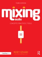
For this reason, the reproduction of the full audible range by a single driver yields quality below professional standards. Therefore, loudspeakers utilize two or more drivers, which are referred to as two-way design, three-way design, and so forth. We must make sure that each driver is only fed with the frequencies it specializes in reproducing. A device called a crossover is used to split the incoming signal into different frequency bands (Figure 8.1). A typical two-way loudspeaker would have its crossover around 2 kHz, sending each band to a different driver. It is impossible to build a crossover that simply slices the frequency spectrum in a brick-wall fashion, so there is always some overlapping bandwidth where identical frequencies are sent to both drivers. The insertion of a crossover into the signal path introduces various issues that color the sound; manufacturers address them in different ways, but no system is perfect.
One issue with multiway design is that the complete frequency spectrum is produced from different points in space. This might cause unwanted phase interaction when the sounds emitted from the different drivers are summed acoustically. To solve this, some manufacturers (such as Tannoy) have designs where the high-frequency driver is fitted into the center of the low-frequency driver (where the dust dome is normally present).
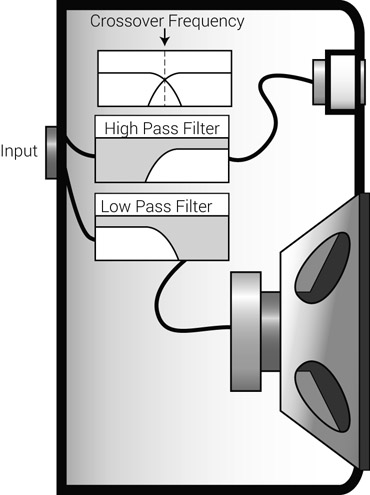
Figure 8.1 Crossover network in a two-way loudspeaker. As the signal enters the speaker, a filter network splits it into two different bands. The low frequencies are sent to the woofer, the high ones to the tweeter.
Two-way studio monitors are able to reproduce the audible frequency spectrum with an acceptable quality. A design that involves more than two drivers will bring about better quality only if the problems introduced by the additional drivers and crossovers are addressed. Naturally, a design that addresses these problems involves a higher price tag. A two-way studio monitor, therefore, is more likely to be a better buy than a domestic three-way loudspeaker of the same price.
All ordinary studio monitors can produce frequencies up to 20 kHz. The lower limit of the frequency response is largely determined by the size of the woofer: 6” and 8” are very common diameters. (The size often forms part of the model name, although it rarely denotes the exact diameter.) These set the lower frequency limit to around 55 and 45 Hz, respectively. A loudspeaker still produces frequencies below these quoted limits, although these are gradually rolled off.
Auratones, near-fields, and full-range monitors
In the early days of mixing, the assumption was that engineers needed the best monitoring system available. But the main monitors (often referred to as “mains”) in commercial studios were far superior to those consumers actually used, so many mixes did not translate well in consumer environments. Mixing engineers soon realized that they needed some speakers that imitated the sound of real-world consumer loudspeakers, and the Auratones 5C, also known as “the cubes,” did the trick (Figure 8.2). These small, and not surprisingly cubic, single-driver speakers had a defined midrange, and they got the nickname “horrortones” because of their unappealing sound. Nevertheless, engineers soon realized that these small speakers could be used for more than simulating the sound of cheap systems.
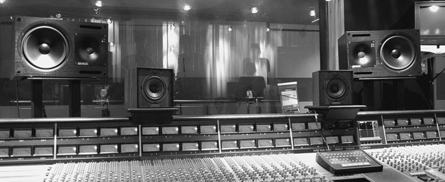
Figure 8.2 The Auratones 5C are the mini-speakers mounted on the meter bridge. Behind them are the Genelec 1031s near-fields.
Source: Courtesy of SAE, London.
Being found in many studios even today, the Auratones are very often used for critical level adjustments (notably vocals), and to evaluate definition. (For example, we can tell there’s a problem if the kick and bass are lost with these monitors selected.) Having pronounced mids, they also help us to tidy up and equalize this area of the mix, where most instruments have their fundamentals and lower harmonics.
But something was still missing between the small Auratones and the big mains, and so a new type of compact monitor was released to fill the gap—the near-field monitors. The acoustical term “near-field” is misleading; a more apt term would be “close-field” monitors, which better describes their position—within the critical distance. Very often, these monitors are placed on top of the console’s meter bridge or on stands right behind it. The vast majority of mixes are done using near-fields. Even in professional studios, where mains exist, mixing engineers might use near-fields for the majority of the mixing process, and only occasionally refer to a different set of monitors. The most common type of near-field nowadays is the active, 8” two-way monitor.
The NS10s
No book about mixing would be complete without discussing the Yamaha NS10s. In 1978, Yamaha released a bookshelf loudspeaker intended for home use called the NS10M. It only took a few years before most music studios had a pair installed. Many people tried to explain the immense popularity of the NS10s. Some said that they were the natural successors to the Auratones, providing a compact speaker, with better sound but not too flattering. Many engineers testified that the midrange definition of these speakers and their tight low-end was highly beneficial for rock and pop mixes. Others declared that if something sounded right on the NS10s, it would translate well on most consumer systems. Another hypothesis is that their distinctive white cones had big shares in propelling them to a cult status. In his book Recording Studio Design, Philip Newell dedicated several pages to the NS10s and presented detailed research aiming to solve the mystery (including a crane-mounted SSL on which the speakers were then fixed). While some engineers wouldn’t touch them with a 10-foot pole, they have become standard in the audio-engineering field, particularly in mixing.
The studio popularity of the NS10s caught Yamaha by surprise. They never designed these speakers for professional use and it soon became apparent that the classic version (NS10M) had some issues when used in studio environments. First, their vertical mounting meant they often obscured the main monitors. Second, they were unable to withstand the abusive studio levels and the tweeters often blew. Finally, and most famously, they had harsh and emphasized highs, which led many people to cover the tweeters with tissue paper. One enthusiastic engineer, Bob Hodas, even researched what type of tissue to use, how many layers, and how far they should be from the tweeters. Yamaha themselves used tissue paper as part of their research while developing a redesigned model, and in 1987 the Yamaha NS10M Studio were released. These were intended for horizontal mounting (and the direction of the label changed accordingly), had softened highs, and more robust tweeters; the cones remained white. As the material used for producing those white cones became unavailable, Yamaha discontinued the production of the NS10s in 2001. Like the Auratones, the NS10s are still found in many studios today, and there is still demand for them in the secondhand market.
Going full-range
While the limited bass response of near-fields might not be an issue for some mixes, it is crucial to have an extended low-frequency response in genres such as hip-hop, reggae, dance, and others. Full-range monitors are so-called because they can reproduce the full audible range from 20 Hz to 20 kHz. They are usually large, high-fidelity monitors that provide higher resolution compared with near-fields. In many studios, these monitors are flush mounted, which enhances their acoustic interaction with the room. Where these exist, we refer to them in order to check and stabilize the low-end of the mix. When switching to the full-range monitors, we hope for an extended low-end without losing level balance. They are also useful when creating separation between the bass and the kick, and due to their high resolution we also refer to them for refinements, such as subtle vocal equalization. The high quality of large full-range monitors makes them the favorite choice for mastering, classical music production, and many recording situations. But their sound is so far superior to anything that most listeners have access to that mixing engineers generally favor the smaller, less impressive, yet accurate near-fields.
Figure 8.3 The NEVE VRL studio at SAE, London. The three types of monitors can be seen here: the full-range are the Genelec 1037Bs, the near-fields are the NS10s and the mini-speakers are the AKG LSM50s.
Subwoofers
Space and budget limitations make full-range monitors a rare breed in home studios, but a dedicated subwoofer provides an alternative. Many professional monitor manufacturers offer a matching subwoofer to their near-fields range, which normally covers the 20–150 Hz range. An optimum configuration for such a setup often involves feeding the stereo mix into the subwoofer first. Most subwoofers have a built-in crossover that splits the frequency spectrum into two bands—the very low frequencies are summed to mono and sent to the subwoofer driver, and all other frequencies are sent to the near-fields through a dedicated stereo output at the subwoofer’s rear.
Choosing monitors
Active vs. passive
The low-level, low-power line output of our desk or computer needs to be amplified to the powerful speaker-level in order for the mechanical components in a loudspeaker to move. There is always a driving amplifier in the signal chain prior to the loudspeaker drivers, and this amplifier can be either built into the cabinet or live as an external unit. A loudspeaker with no integrated amplifier is known as a passive speaker, and must be fed with a speaker-level signal that has been amplified by an external amplifier. Most multiway speakers contain a crossover within their cabinet. In the case of passive speakers, the crossover is a passive one (there are no active components) and is designed to operate at speaker level. External amplifiers have a huge influence on the overall sound. The NS10s, for example, can sound distinctively different when driven by different makes with different power ratings. There is some critical interaction between an amplifier and a loudspeaker— it is, essentially, one system—and the amplifier determines many aspects of the overall sound, such as transient response, low-frequencies reproduction, and distortion. Matching an amplifier to a loudspeaker is never an easy affair.
When connecting an amplifier to passive speakers, the following should be adhered to. Cables must be as short as possible and of equal length (for both the left and right speakers); if they are not of equal length, there will be stereo imbalance between the two speakers. It is important to make sure that the terminals are correctly connected with plus to plus and minus to minus; if the terminals are crossed on both speakers, the two channels will be in phase, but the overall mix will be phase-inverted. This means that the speaker cones will move backwards instead of forward, and vice versa, and might affect the sound. (This is based on the idea that cone suspension does not behave identically between front and back movements. As part of quality control, some mastering engineers check their masters with both speakers inverted.) An easy way to diagnose such incorrect cabling is when a kick pulls the cone rather than pushes it. If only one speaker is cross-connected, then the left and right speakers are phase-inverted, which creates an extremely unfocused, out-of-speakers sonic image that makes accurate mixing an impossible task. Conventionally, the positive (plus) terminals are connected using the red wire (as in the audio proverb: “red is ring, right, and positive”).
Loudspeakers with a built-in amplifier are called powered speakers. These have line-level inputs, commonly balanced XLR or ¼”. There involve two common designs: the first involves a single amplifier followed by a passive crossover; the second involves an active crossover followed by two or more amplifiers—one for each driver. A speaker that has an active crossover is called an active speaker, and if there is more then one built-in amplifier it is called bi-amped or tri-amped, depending on the number of amplifiers. The majority of powered studio monitors are active and multi-amped.
Active monitors are often shielded, which drains magnetic interference that might potentially occur between the speaker and other electronic devices such as old CRT screens. Some newer models also have digital inputs. While placing an A/D converter within a loudspeaker might seem to make as much sense as placing a blender in a microwave, such practice prevents analog interference and minimizes the chance of ground loops.
There are not many cases in mixing where one thing has such a clear advantage over something else, but active speakers provide many advantages over passive ones. The fact that a speaker has a built-in amplifier removes the guesswork of matching an amplifier to a loudspeaker and leaves this to the professional designers. Manufacturers can fine-tune the performance of each component for optimal results, and usually the outcome is more cost-effective. Many active speakers include protection circuitry (built-in limiters) that makes them resistant to abuse. If we ignore room acoustics, identical models of active speakers installed in different places would sound highly consistent since they are always driven by the same built-in amplifiers. But, for all its advantages, there is no guarantee that an active monitor will perform better than a passive one. Although active speakers continue to gain popularity, passive monitors are still manufactured, some receiving much acclaim. With all of its disadvantages, perhaps the one benefit of a passive setup is increased configurability—the ability to mix and match amplifiers and speakers for truly fine-tuned results—something the seriously techie take pleasure in.
Enclosure designs and specifications
You may already be aware that some studio monitors have holes in their enclosure (called “ports,” “vents,” or “ducts” in professional jargon). Such a design is known as dipole design and includes sub-designs such as vented enclosure (e.g., Genelec 1031 A), bass reflex (e.g., Dynaudio BM 6 A), and transmission line (e.g., PMC TB2S-A). Designs with no ports have the air within the enclosure sealed, and are known as monopole designs. The most common monopole designs are either sealed enclosure (e.g., Yamaha NS10s) or auxiliary bass radiator, which is also known as ABR or passive radiator (e.g., Mackie HR824). While the concept behind the different designs is a fascinating one, it teaches us nothing about the fidelity of the final product—none of the designs ensure a better quality than the others.
There are, however, a few things worth mentioning. Dipole designs are more efficient and provide an extended low-frequency response compared with monopole designs of the same size (although the low-end extension is potentially unfaithful and an inaccurate one). Conversely, monopole designs provide better damping of the woofer cone when the input signal dies abruptly. After a gated kick dies out, momentum will keep the woofer cone moving for a while before it comes to a halt; this extraneous movement generates un wanted low frequencies. While the woofer in monopole designs comes to a halt very quickly, waterfall plots show that some dipole monitors can produce frequencies lower than 100 Hz for more than 100 ms after the input dies. Sound-wise, monopole designs are said to deliver tighter bass response, and it is no wonder that many professional subwoofers employ such a design.
Like many audio devices, the specification sheets for monitors are often inconsistent and can be misleading, teaching us very little about the actual quality of the product. Technical measurements such as signal-to-noise ratio, harmonic distortion, and maximum output level are often dependent on the system used during measurements, and can be easily manipulated in favor of the manufacturer. The monitors’ frequency-response graph, which demonstrates the dips and bumps of various frequencies across the spectrum, has no bearing on the perceived quality or accuracy of the speaker. A speaker with a relatively flat frequency response does not guarantee a better quality than a speaker with noticeable wiggles. Of course, one specification that we do care about is the quoted frequency range of the speaker, specifically its lower limit. There is an important difference between a speaker that rolls off low frequencies at 70 Hz and one that does so at 50 Hz. Here again, manufacturers can manipulate the specifications to show better figures.
![]()
Frequency response specifications are often given with a quoted error range, for example 58 Hz–20 kHz (±2 dB). A frequency response within a ±2 dB range means wiggles are no more than 2 dB from the average. The smaller the error range, the better, as ±10 dB means that there is normally at least one wiggle that is 10 dB away from the average response. Wiggles aside, higher error range is sometimes used to “extend” the lower frequency limit of a speaker on specification sheets. This is due to the fact that the lower-frequency limit is often determined by the lowest frequency in the lows roll-off range that is outside that error range. So the same speaker will have an extended lower-frequency specification with an error range of ±10 dB compared to that of ±2 dB. An error range of ±2 dB typically means the manufacturer does not take advantage of this range to extend the frequency range; ±10 dB should be treated as suspicious; when no error range is provided, the frequency response specification is generally useless.
A choice of experience
It should be clear by this point that monitors should not be selected based on their design or specifications, but on their actual sound. To be sure, one thing we do not want from our monitors is flattering sound—we want them to reveal problems rather than conceal them. Accuracy and detail are the key qualities we are after. “Because they sound good” is the poorest reason to favor one brand over another. Unfortunately, many buyers fail to comprehend this. Even worse, some manufacturers will sacrifice quality in order to make their monitors more appealing in quick-listening tests. Some retailers have a showroom containing a clutter of many brands and models in an arrangement that bears no resemblance to the actual positioning of monitors in a real studio setup. This supermarket approach does the monitors no justice whatsoever, as often their sound can be greatly influenced by their placement. It also often means that we are unable to assess other critical aspects, such as stereo image.
By way of analogy, buying monitors is like buying a mattress—no matter how good it looks in the shop or how sophisticated the specifications are, we can only tell how comfortable a mattress is after using it for a few days. Mixing engineers will usually become accustomed to their monitors after a while—and having got used to them will remain loyal and depend on them. There truly isn’t a “magic model”—what one praises the other dislikes. Even the NS10s have been the subject of debate. As a guideline: the higher the price tag, usually, the higher the quality one should expect.
The room factor
No pair of speakers sounds the same, unless placed in the same room.
It may seem unreasonable to expend as much money on acoustic treatment as on monitors. But the truth is that an expensive set of high-fidelity monitors is pointless if deficiencies in room acoustics are not treated. We have mentioned the frequency-response graphs and waterfall plots of a loudspeaker. These measurements are taken by manufacturers in anechoic chambers, where the room itself is not a variable. This is only fair, as it would be unreasonable for each manufacturer to use a different room—each with its own unique effect. If manufacturers were to record their measurements in domestic rooms, their results would yield variations that could be six times worse than the anechoic measurements. In practice, these untaken worse measurements are the ones our rooms produce—to this extent or another.
Professional mixing facilities are designed by specialists; therefore, this section will only cover the most relevant aspects for smaller project studios. A complete discussion of all the acoustic factors that affect our monitoring environment is far beyond the scope of this book, but the most important factors for our purposes are briefly covered below.
Room modes
![]()
Room modes are discussed in great detail in many books. A full exploration of room modes is long, technical, and requires some background knowledge. Below is a short and simplified explanation of this topic.
Low frequencies propagate in a spherical fashion. For the sake of simplicity, imagine that low frequencies emitted from our monitors travel equally in all directions. Also, whenever low frequencies come into contact with a surface, imagine that a new sound source is created at the point of contact, as if a new speaker has been placed there.
The simplest way of describing standing waves involves the use of two parallel walls. Sound emitted from a speaker will hit the left wall, bounce back to the right wall, and then bounce back and forth between the two. We can think of the sound as trapped between the two walls. Since every time sound hits a surface some of its energy is being absorbed, after a while the sound dies out. However, continuous monitor output might constantly reinforce waves already trapped.
If the frequency of the trapped waves is mathematically related to the length of the trap, a predictable interaction between all the trapped waves will cause that frequency to be either attenuated or boosted at different points along the trap. For example, halfway between the two walls that frequency might be barely audible, and next to the wall that frequency might be overemphasized. Waves with these characteristics are called standing waves and a problematic frequency is described as a resonant room mode. The laws of acoustics say that if a specific frequency is trapped in a room, all of its harmonics are also trapped. For example, if 50 Hz is the lowest resonant mode, then 100, 150, 200, 250 Hz, and so forth will also be trapped.
If traps could only form between two parallel surfaces, each room would only have a relatively small set of three problematic frequencies (one for each dimension) and their harmonics. However, traps can also form between four or six surfaces, which results in a complex set of room modes. If two room dimensions are identical, then the problem is twofold since the same frequency is trapped along two dimensions. Cubic rooms are the worst since all three dimensions are identical. Rooms with dimensions that share common multiples (e.g., 3 × 6 × 9 m) are also very problematic. Despite the common belief, non-parallel walls do not rectify the standing waves problem—they only make the room modes distribution more complex.
The lowest resonant frequencies are also the most profound ones. In small rooms, these lower frequencies are well within our audible range. The formula to calculate these fundamental frequencies is quite simple: f = 172 / d (“d” refers to the dimension in meters). So, for example, a dimension of approximately 3 m will cause a fundamental room mode at 57 Hz. The bigger the room, the lower the fundamental resonant frequency is. For example, a dimension of 8 m will cause a room mode at 21.5 Hz, which is less critical than 57 Hz for mixing applications. Also, as we climb up the frequency scale, the increased density of room modes makes them less profound, and around 500 Hz we can disregard them. In bigger rooms, problems start lower on the frequency scale, and also end lower— room modes might no longer be an issue above 300 Hz. Big rooms are therefore favored for critical listening applications such as mixing or mastering.
It is crucial to understand that room modes always cause problems at the same frequencies, but the problems are not consistent throughout the room. Eventually, each point in the room has its own frequency response. Room mode calculators are freely available over the Internet—they will output a graph showing problematic frequencies given the room dimensions. However, they do not tell us where exactly in the room we should expect these problems to be noticeable, or in other words what the frequency response of each point in the room will be.
Luckily, we can quite easily perform a practical test that teaches us just that. It involves playing a sine wave and comparing different frequencies between 20 and 600 Hz. Obviously, we usually listen at our mixing position, but moving around the room would demonstrate how drastically one frequency can be attenuated or boosted at different points across the room. The results of this experiment can be quite surprising for people trying it for the first time—you might learn that a specific frequency (say, 72 Hz) is inaudible when you sit but clearly heard when you stand; you might also learn that one frequency (say, 178 Hz) is noticeably louder than a nearby frequency (say, 172 Hz).
One more aspect of room modes worth discussing is that they affect the speakers’ ability to reproduce problematic frequencies. If a speaker is positioned at a point where standing waves cause a specific frequency boost, the speaker will be able to produce more of that frequency. The opposite case only applies to monopole speakers—if the speaker is located at a point where a specific frequency is attenuated, the driver will have difficulties producing that frequency.
![]()
Provided on the website are a few 30-second-long test tones for readers to experiment with. While listening to each frequency, move around your room to see how at different points that specific frequency is boosted or attenuated. Most readers trying this in a domestic room should recognize at least one frequency that suffers noticeable level variations across the room, which is the consequence of room modes.
- Track 8.1: Sine 60 Hz
- Track 8.2: Sine 65 Hz
- Track 8.3: Sine 70 Hz
- Track 8.4: Sine 75 Hz
- Track 8.5: Sine 80 Hz
- Track 8.6: Sine 90 Hz
- Track 8.7: Pink Noise
Pink noise provides equal energy per octave and therefore is commonly used for acoustic measurement. While listening to this noise when seated in the listening position used for mixing, readers are encouraged to move their head back and forth, then sideways. Room modes might cause variation in low frequencies, while early reflections and the directivity of the tweeters might cause variations in high frequencies. One characteristic of a well-tuned room is that moving your head while listening to the music (or pink noise, for that matter) hardly alters the perceived frequency content.
Treating room modes
You might instinctively think that you could compensate for room mode effects by inserting a graphic equalizer before the monitors. If 172 Hz is attenuated by 6 dB, why not boost that frequency by 6 dB? When it comes to rectifying the acoustic response of the room, monitor equalization is considered futile and in most cases will do more harm than good. There are a few reasons for this. First is the simple fact that any equalization process has its own quality penalty, especially when using less than high-end equalizers (a high-precision graphical EQ can easily exceed the cost of acoustic treatment, which will yield better results). Second, the room response varies in relation to different positions within the room. It would make sense to compensate for audible problems at the listening position, but such a treatment can cause greater problems at other positions in the room, including the points where the monitors are situated. Last, there is a difference between the way long sounds and transients excite room modes. Compared to the sound of a kick, room modes would more greatly affect the sustained note of a bass guitar. Equalizing the monitors to make the bass sound good might make the kick sound boomy.
It is worth remembering what exactly we are trying to fix. The overall response at different places in a room is dependent on both the direct sound and the reflected sound. It is room modes caused by reflections that make a perfectly balanced mix unbalanced. But while trying to rectify room modes, monitor equalization also affects the direct sound, which can represent a well-balanced mix. There are situations where monitor equalization is appropriate, but these only happen when the direct sound itself experiences frequency alterations. For example, placing a loudspeaker next to the wall causes low-end emphasis.
To compensate for this, many active monitors offer switches for different degrees of bass roll-off. But this type of equalization is not intended to correct room modes; it is merely concerned with correcting coloration of the direct sound.
It should be clear by now that in order to treat room modes, we need to treat the reflections. This is achieved by two acoustic concepts: diffusion and absorption. Diffusers scatter sound energy, including the low-frequency energy of standing waves. Absorbers soak up sound energy. Diffusers are less welcome in small rooms, partly due to the fact that, in close proximity to the listening position, they can sometimes impair the overall response rather than enhance it. Absorbers, on the other hand, are a very practical solution. The idea is simple: if we absorb sound as it hits the wall, we damp the reflected energy, and therefore minimize the effect of standing waves. In anechoic chambers, there are no reflections and therefore no standing waves, but the unnatural response of these reflection-free spaces makes them highly unsuitable for mixing, and some people even find them unbearable. In most mixing situations, we want all reflected frequencies to become inaudible within approximately 500 ms. There is little point in covering our walls with excessive absorbent material, since absorbers are most effective at high frequencies— these are readily absorbed by normal soft materials as well.
And so, in order to minimize the effect of room modes, the key is to target the low frequencies. Both low-frequency diffusers and absorbers are an issue in small rooms since in order to be effective they have to be of considerable depth. For example, in order to absorb 85 Hz, an absorber would have to be around 1 m deep. Companies such as RPG, RealTraps, Auralex, and many others offer affordable, relatively small bass traps that fit most project studios and provide good damping of room modes. It should be pointed out that placing bass traps in a room will not reduce the bass response in any unwanted way. The first reason for this is that by minimizing the effect of standing waves, a smoother frequency response is achieved throughout the room, which in turn means that, at various points, low frequencies will be heard better. Second, bass traps help in reducing the decay time of reflected low frequencies (even non-resonant ones), which, in small, domestic rooms, is usually longer than desired.
Flutter echo
![]()
Track 8.8: Flutter Echo
Flutter echo caused by handclaps in a domestic room.
Track 8.9: Snare No Flutter
The source snare track.
Track 8.10: Snare Flutter
An artificial simulation of flutter echo using a 30 ms delay (which roughly corresponds to walls 10 m apart) with feedback set to 50 percent. Although the effect is exaggerated in this track, it demonstrates the timbre coloration that can occur in real life.
Snare: Toontrack EZdrummer
While room modes are the result of interaction between reflected low-frequency waveforms, flutter echoes are caused by mid and high frequencies bouncing between two parallel reflective surfaces. In small rooms with reflective surfaces, we can clap our hands in order to produce such an effect. It sounds like quick, distinctive echoes with a metallic, ringing nature, similar to the jumping sound effect in cartoons.
The addition of flutter echo to percussive instruments, such as snares, is like the addition of non-musical delay, which colors the timbre and adds some metallic tail. For project studios, absorbers are the most practical solution to treat flutter echo. These are placed on the offending walls.
Early reflections
Reflections bouncing from nearby surfaces blend with the direct sound. Since they travel a longer distance, they arrive with a specific phase relationship to the direct sound. Mid and high frequencies are more problematic due to their shorter wavelengths. Early reflections happening within the first 40 ms cause comb filtering—a set of boosts and cancellations across the perceived frequency response. There is also smearing of the stereo image due to the delayed arrival of the direct sound and its reflections. Early reflections commonly bounce from the desk, sidewalls, and ceiling. But sound waves are not limited to specular travel—a sound wave hitting the edge of a computer screen can radiate back to the listening position as well.
Apart from effective positioning, which is discussed next, absorbers are used to suppress these early reflections. Since the mid and high frequencies are the most problematic ones, the absorbers do not have to be extremely deep—a 50 mm acoustic foam usually gives the desired results. Prioritizing the placement of these tiles is based on two factors: the nearest surfaces are treated first, and in the case of walls absorbent material is first placed halfway between the sound source and the listening position. When possible, nearby objects (such as computer screens) are protected by absorptive material, even if the reflections they cause are not specular.
![]()
Track 8.11: Left Right 1 kHz
Depending on the monitoring environment, this track might, or might not, demonstrate problems caused by early reflections. A 1 kHz sine toggles between the left and right channels in a 2-second interval. Ideally, the test tone should appear to come clearly from the speaker it is emitted from. Also, there should be no difference in level, tone, or stereo width and focus between the two speakers. While seated in the listening position, moving your head around might reveal differences between the two speakers.
Positioning monitors
Among all the acoustic-related enhancements we can apply, monitor positioning is one of two things that do not cost money, the other being reading the manual for our monitors. Nearly all monitor manuals include some practical advice regarding ideal placement and configuration of the speakers.
Where in the room?
Perhaps the most crucial positioning decision is where exactly the listening position is, which is largely determined by the position of the monitors themselves. Room modes affect the frequency response at the listening position and the ability of the speakers to reproduce specific frequencies. Comb filtering also has an effect on what we hear. Since the problems caused by room modes and comb filtering are more profound in small rooms, minor changes to the listening or monitor position in such rooms can have a dramatic effect. This makes the monitor and listening position even more crucial in small mixing environments, such as most project studios. Unfortunately, it is in these project studios where space limitations provide little or sometimes no option for monitor placement. Ideally, we would like to try out different listening and monitor positions in an empty room, usually while playing a familiar mix and test tones. It takes three people moving about—two holding the monitors and the other listening. Despite the time and technical issues involved in connecting the monitors and moving them around, the benefit from correct positioning could be invaluable.
Usually, there is only one dimension in question. The height at which we intend to sit when mixing will determine the height of the monitors. Since left/right symmetry results in a more accurate stereo image, the listening position is often halfway between. Unfortunately, halfway between any two walls is often where profound frequency imbalance is caused by a fundamental room mode. One thing we can do is to experiment to see whether it is the length or the width of a rectangular room that gives us fewer problems. Since the height is fixed, and on the left/right axis we usually sit in the center, all we have to experiment with is the front/back movement of our listening position and our speakers. It is suggested by some that the ideal listening position might be one-third of the way along the dimension. Nothing, however, beats experimentation.
The equilateral triangle
The most common monitor setup involves an equilateral triangle. The monitors are placed on two vertexes, facing the listener with their rays meeting at a focal point right behind the listener’s head (Figure 8.4). Many position the monitors in such a way by using a string to measure an equal distance between all vertexes (the two speakers and the focal point). It is vital that the speakers are angled toward the listener—parallel speakers produce an extremely blurred stereo image with an undefined center. Although the equilateral triangle is a recommended standard, it is worth experimenting with variations involving a wider angle at the focal point. An isosceles with 90° will result in a wider stereo image, but sometimes at the price of an unfocused center.
After the initial positioning of the speakers, it is worth playing a familiar mix and moving the head back and forth to find the best listening position. Moving the head backward will narrow the stereo image, while moving it forward will result at some point in a distorted stereo spread and blurred center. There is usually only one point where the stereo image appears to be optimal.
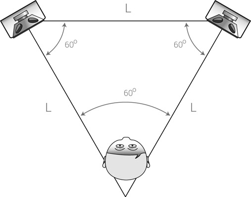
Figure 8.4 An equilateral triangle speaker setup. The angles between the speakers and the focal point behind the listener’s head are all 60°. This creates an arrangement where the distance between the two speakers is equal to the distance between each speaker and the focal point.
How far?
Once the optimal focal angle has been determined, we can move the speakers closer or farther away from the listener while sliding them on the imaginary isosceles sides. While the ear should always be the final judge, a few points are worth considering:
- It takes time for the waves from the different drivers to unite into a cohesive sound. If the speakers are too close to our ears, we can hear the sound as if coming individually from each driver (e.g., highs from the tweeter, lows from the woofer). In such cases, small head movements would result in great changes of the perceived sound.
- The closer the speakers, the more phase differences between the left and right ears, which results in a less solid stereo image.
- The farther away the speakers are, the wider the stereo image becomes, which makes panning decisions easier and reverbs somewhat more defined.
- The farther away the speakers are, the smaller the direct sound ratio is compared with the reverberant room sound. In a small room with profound resonant room modes, this is not desirable.
- Considering the wall behind the speakers, the farther the speakers are from the listener (therefore closer to the wall), the louder the low frequencies will be. This is caused by low frequencies bouncing from the back wall and returning to superimpose on the direct sound. As already mentioned, many active designs feature a bass roll-off switch to compensate for this phenomenon.
- The farther away from the listener, the closer the speakers are likely to be to the back and sidewalls, which can result in more comb filtering.
Horizontal or vertical?
Experts strongly recommend mounting monitors vertically. If the monitors are mounted horizontally, side movements of the head result in individual distance changes from each of the drivers, and thus unwanted coloration of the frequency response. If, for whatever reason, monitors are mounted horizontally, the general recommendation is for the tweeters to be on the outside. This ensures a wider stereo image, and some also claim a better bass response.
Very high frequencies are extremely directional; it can easily be demonstrated how a frequency of 18 kHz coming from a single speaker can only be heard if the ear is placed in a very specific point in space. Therefore, tweeters should be placed at ear level, or, if the monitor is angled, the tweeter’s normal should be directed toward the ear.
Damping monitors
Various devices are used to separate the monitors from the surface on which they are mounted. Most widespread are isolation pads made of dense acoustic foam (Figure 8.5) and metal spikes. Monitor decouplers function in two principal ways. First, they isolate the monitor from the stand (or desk), ensuring that the speaker operates independently, with no back-vibrations from the stand interfering with the monitor operation. Second, they prevent transmission of vibrations onto the stand, which can generate unwanted resonance. The resonance of a hollow metal stand can easily be demonstrated if you clap your hands next to it. Such stands are designed to be filled with sand, which increases their mass and minimizes resonance. Also, sound generally travels faster through solid matter than through air. It is possible for sound to travel through the stand and floor and reach our body before the sound traveling through air does, possibly confusing our perception of low frequencies. Both foam and spike decouplers are fairly cheap, yet are known to have a highly positive effect on monitor performance. Mostly, they yield a tighter, more focused bass response.
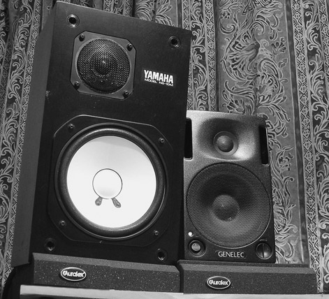
Figure 8.5 The Auralex MoPAD monitor isolation pads. Both a Yamaha NS10 and a Genelec 1029 are shown here resting on the Auralex MoPADs.
A/B realm
Virtually every serious mixing studio has more than one pair of monitors. Sometimes there might even be more than one pair of near-fields. Project studio owners can also benefit from having more than one pair of monitors. Different brands vary in characteristics such as frequency response, detail accuracy, depth imaging, and stereo imaging. Having more than one brand lets us compare various aspects of the mix using different references, and can help us make important mixing decisions, especially while stabilizing the mix. Different products on the market, often called control room matrices or command centers, let us toggle between the different pairs of speakers. The Mackie Big Knob in Figure 8.6 is one of them. Cubase provides internal functionality that achieves the same, provided the audio interface has more than one stereo output.
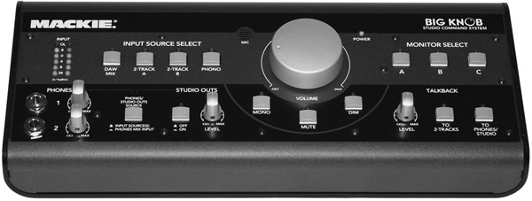
Figure 8.6 The Mackie Big Knob. Among the features of this studio command system are monitor selection and mono summing.
Very often, when a few sets of monitors are installed, only one is used for the majority of the mixing process, with the others used for reference or specific tasks. It is important to remember that each pair of monitors will sound different. This can make frequent jumping between one set to another more confusing than helpful—as mixes sound different on each set, there’s no solid reference for decision-making and one might be applying changes simply because of the sonic differences between two sets. It is therefore advisable to take a short break before changing to a new monitoring system; this way, the sonic differences between the monitors will be less noticeable.
Headphone mixing
![]()
Having used monitors exclusively, some professional mixing engineers might be shocked to find a section on mixing using headphones in a book on mixing. Others may understand, having used headphones as a reference on occasion.
Truth be told, many people nowadays mix in bedrooms, where noise-level considerations exist (late hours, neighbors, etc.), and rooms may be poor for listening. Thus, mixing on headphones is not only sometimes the only option, but it may actually have some advantages. Some of the readers of this book, as it turned out, use headphones exclusively while mixing, so the disadvantages of doing so also need to be discussed.
Headphones vs. speakers: the theory
Before we delve into the practical side of headphone mixing, here is a short theoretical introduction.
When listening on headphones, both the left and right ears are fed exclusively with the corresponding channel. This means that the left-channel signal reaches the left ear only, and the right-channel signal reaches the right ear only (Figure 8.7a).
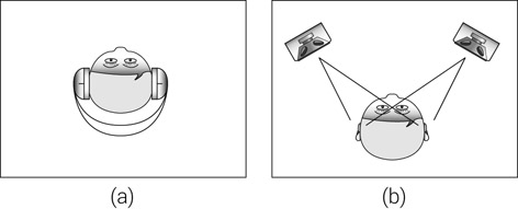
Figure 8.7 Headphones vs. speakers. With headphones, each ear is fed with the corresponding ear channel only. With speakers, each channel reaches the near ear first, and shortly after the far one.
With speakers, this is not the case. Sound from each speaker reaches the nearest ear first and the farther ear soon after (Figure 8.7b). Effectively, each ear gets the signal from the nearest speaker blended with the slightly delayed signal from the other speaker. This results in the following:
- Sounds from one speaker can mask sounds from the other.
- Overall smearing of the image for any sounds not panned to the extremes. Most severe smearing happens with sounds panned center.
- Curvature of the sound image as center-panned sounds appear deeper due to the delay between the late arrival of sound from the far speakers.
None of this happens with headphones, but stereo was conceived with speakers in mind, and for many decades now music has been made assuming playback through speakers. Our equipment, notably the design of our pan pots (but also that of stereo effects such as reverbs), assumes the same. Mixing engineers mix using and for speakers. But how do these mixes translate onto headphones?
The key difference between listening to music through speakers and headphones has to do with the way our brain localizes sounds. How this happens is based on the findings of Helmut Haas and is implemented through Alan Blumlein’s invention of stereo, both explored in greater detail in Chapter 14. For now, it is sufficient to say that a sound from one speaker will completely mask a similar sound from the opposite speaker if the former is approximately 15 dB louder. Practically, if the signal sent to one speaker is roughly 15 dB softer than a similar sound sent to the opposite speaker, the sound will appear to be coming entirely from the louder speaker. But with headphones, no such masking occurs, as the sound of each channel doesn’t arrive at the opposite ear. To make a sound appear as if it is coming entirely from one ear, roughly 60 dB of attenuation is required on a similar sound arriving at the other ear.
In the way pan pots are designed, when one pans from the center to the left, one should expect the location of the sound to correspond to the pot movement. This does not happen with headphones, where the sound seems to shift only slightly off the center first, before quickly “escaping” to the extreme just before the pan pot reaches its extreme position. It is hard to place sounds anywhere between the slightly off-center position and the very extreme when listening on headphones. In fact, in the way standard pan pots work, it is next to impossible. Positioning instruments on the sound stage is much easier when listening through speakers. Applications such as Logic offer “binaural” pan pots, which tackle this exact problem and can achieve much better localization using headphones, but the penalty is that they do so by altering the frequency content of the signal sent to each ear, thereby altering the overall frequency spectrum of the instrument. Also, these types of “binaural” mixes do not translate well on speakers. In addition to all that, the sound stage created by speakers is limited to the typical 60° between the listener and the two speakers. With headphones, the sound stage spans 180°.
Mixing engineers work hard to create sound stages in mixes using speakers. When these mixes are played through headphones, these sound stages appear completely distorted. While this does not seem to bother most listeners, most serious music buffs insist that listening to music via speakers is far more pleasing, largely due to the lack of spatial sense when using headphones.
The dominance of speaker mixes was never questioned until not long ago, when portable MP3 players and their integration with cellular phones became so widespread. It is a valid question to ask why we still mix using (and for) speakers when so many people nowadays listen via headphones. There is an unexploited opportunity here for record labels to produce “speaker” and “headphone” versions. This would make sense not only from a mixing point of view, but also from mastering, consumer, and label revenue points of view.
The advantages
Some recording and mixing engineers take their reference headphones to studios they are not familiar with. Headphones provide a solid reference, and their sound only alters when different headphone amplifiers are used. As previously explained, the room plays a dominant part in what we hear with a speaker setup—the sound headphones produce is not affected by room acoustics or modes.
This is very important for rooms with flawed acoustics, such as many bedrooms and project studios. In such rooms, a good pair of headphones, together with a good headphone amp, can be a real aid. Having room modes out of play means that the range between 80 and 500 Hz can be more evenly reproduced, although studio monitors still have an advantage reproducing very low frequencies compared with most headphones. Other acoustic issues simply don’t exist when using headphones; for example, the comb filtering caused by early reflections, the masking between the left and right speakers, and even the directivity of the tweeters. It can be generalized that, as far as frequency reproduction is concerned, the results we get using good headphones are more accurate than those generated by speakers in a flawed room.
For many compression, gating, and dynamic range tasks, speakers do not provide a clear advantage over headphones—as long as the processing does not affect the perceived depth of the instrument, headphones can be useful.
The disadvantages
While headphones can be great when dealing with frequencies and useful when treating certain dynamic aspects of a mix, there are also a few disadvantages in using them, and they are almost useless for some mixing tasks.
As discussed, the spatial image created by headphones is greatly distorted and conventional tools make it very hard to craft appropriate sound stages on headphones. Any sound stage decisions we make, whether left/right or front/back, are better made using speakers. As depth is often generated using reverbs, delays, or other time-based effects, the configuration of these effects benefits from using speakers.
Earlier in the chapter, it was stated that ideal mixing rooms aim to have the reverb within them decaying at around 500 ms and that anechoic chambers, where no reverb exists, are far from ideal. As we lose the room response when using headphones, we also lose the reverb, so it is as if we mix in a space similar to an anechoic chamber. Most people find this less pleasant. The lack of room reverb, together with the close proximity of the headphones’ diaphragms to our eardrums, mean that ear fatigue is more likely to occur. At loud levels, headphones are also more likely to cause pain and damage to the eardrum.
Headphone amps
In the same way as power amps influence the performance of passive speakers, headphone amps influence the performance of headphones. Cheap headphone amps colorize the sound, can cause audible distortion (especially at loud levels), and tend to present an undesired correlation between frequency response and listening levels. A good set of headphones together with a good headphone amp can easily cost as much as a good active near-field monitor.
Which headphones?
Earphones are small constructions with very small diaphragms that render them unsuitable for critical listening tasks. Thus, this section focuses on headphones, for which there are three principal designs:
- Closed-back—this design aims to achieve maximum isolation between the sound generated by the headphones and the environment. This is useful in recording situations when a minimum amount of headphone leakage is sought (vocal overdubs, for example). It is also useful when a bassist stands next to the drummer in a studio where the loud drums mask the sound produced by the headphones. Outside studios, this design is also used in noisy environments. In order to achieve maximum isolation, the cups have their back sealed and the headband normally presses the cups against the head. The closed cup provides some design challenges as it means some sound reflects back to cause comb filtering. This design is also normally unsuitable for long listening periods as the pressure applied to the head can cause discomfort.
- Open-back—this design puts audio quality and comfort first, making it most suitable for critical listening applications and the long listening periods that mixing invariably requires. The back is open to prevent comb filtering and so the sound normally travels both ways easily with little isolation. For maximum comfort, most reference headphones will have cushions bigger than the pinna (the outer, visible part of the ear), and the headband normally applies little pressure to the head around the ears. Long-term usage can result in pain at the top of the head against which the weight of headphones applies, so more expensive designs are lighter. Similarly, cushions on better designs are also made from materials that absorb sweat yet dissipate heat for additional comfort.
- Semi-open—this is a marriage between the two previous designs, aimed at providing moderate isolation when such a thing is needed. An example is live sound, when an engineer might wish to hear the sound coming from the front of house yet still be able to hear either soloed tracks or a communication feed.