
19
Gates
Following compressors, gates are perhaps the second most common dynamic range processors in mixing. Gates are also called noise-gates— a name that hints at their traditional usage as noise eliminators. In the past, tapes and analog equipment were the main contributors to added hiss. Nowadays, digital technology tends to allow much cleaner recordings. Still, in project studios, unwanted noise on a recording might be the outcome of ground loops, a computer fan, or airborne traffic. Noise, however, is not the only thing gates are employed to reduce. The rumble produced by the floor tom when the rest of the drum kit is played is often gated. The hi-hats spill on a snare track and the headphone spill on a vocal track are two more examples. In addition to their traditional role, gates are also used for more creative tasks, such as tightening drums, adding punch, or applying dynamic movement.

Figure 19.1 A gate plugin. The MOTU MasterWorks Gate.

Figure 19.2 Inside a gate. The vertical chain shows the main side-chain stages, and the controls linked to each stage.
Controls
Threshold
Gates affect signals below the threshold—these are attenuated, sometimes to a degree that is considered muting. Signals above the threshold pass through unaffected, unless some attack is applied. A gate only cares whether the signal is above or below the threshold; a gate is said to be closed when the signal is below the threshold and open when the signal is above it. Figure 19.3 illustrates the function of a gate on a snare.
Threshold settings on a gate might seem straightforward—we set the threshold below the wanted signals and above the unwanted signals. In practice, this affair can be tricky since a certain threshold does not always meet both criteria. For example, the snare in Figure 19.3 lost some of its attack and much of its decay. We could retain more of both by lowering the threshold, but this would cause false triggering by the hi-hats. Solutions to this common issue are discussed later on. In the meantime, we should note:
Lower-threshold settings on a gate are often sought as they help in retaining more of the natural attack and decay.

Figure 19.3 Gate threshold function. The original signal before gating involves a single snare hit and a few hi-hat spikes we wish to eliminate. The threshold is set above the hi-hat peaks, so the gate would only open once the snare hits. The gate would close as the snare hit drops below the threshold. After gating, only the loud portion of the snare remains.
![]()
The source snare track used in the following tracks, where the aim is to gate all drums apart from the snare.
Track 19.2: Snare Threshold –40 dB
A –40 dB threshold is too low. The drums hardly drop below the gate’s threshold, and when they do the gate produces abrupt level changes.
Track 19.3: Snare Threshold –30 dB
The kick, toms, and later the hi-hats still overshoot the –30 dB threshold. There are even more abrupt drops in level on this track.
Track 19.4: Snare Threshold –20 dB
Apart from a few tom hits, it is only the snare that overshoots the –20 dB threshold.
Track 19.5: Snare Threshold –10 dB
Only the snare triggers the gate opening here. However, due to the high threshold, some of the snare’s leading edge, and much of its decay, are gated as well.
Plugin: McDSP Channel G
Hysteresis
To allow quick gate opening once the signal has exceeded the threshold, the level detection on most gates is based on peak-sensing. Level fluctuations are more profound with peak-sensing than with RMS. While fluctuating in level, signals may cross the threshold in both directions many times over a short period of time. This causes rapid opening and closing of the gate, which produces a type of distortion called chattering (see Figure 19.4a).

Figure 19.4 Hysteresis control on a gate. (a) A gate with a single threshold and no hysteresis control. Chattering is introduced due to the rapid opening and closing of the gate, which is triggered by quick level changes. (b) A gate with hysteresis control. The gate only opens as the signal overshoots the opening threshold and only closes as the signal drops below the closing threshold. Level variations between the two thresholds do not cause toggling of the gate state, thus no chattering occurs.
One way to overcome this is by having two thresholds—one above which the gate opens, another below which the gate closes. Having two threshold controls would be cumbersome since adjustments to one will call for adjustments to the other. Instead of providing two controls, gates offer a single threshold and a control called hysteresis. The threshold is the opening threshold, and the hysteresis determines how many dBs below it the closing threshold is set. For example, with the threshold set to –20 dB and hysteresis to 5 dB, the closing threshold would be at –25 dB. Figure 19.4b illustrates this.
Many gates do not offer hysteresis as an adjustable control, but have a built-in setting fixed between 4 and 10 dB. When hysteresis control is given, these figures provide a good starting point.
![]()
A kick sent to a reverb, which is gated in the following tracks.
Track 19.7: Kickverb No Hysteresis
The chattering on this track was caused by the reverb level fluctuating around the gate’s threshold (–37 dB).
Track 19.8: Kickverb Hysteresis –6 dB
With –6 dB of hysteresis, the gate opens at –37 dB and closes at –43 dB. As can be heard, this reduces chattering but does not eliminate it.
Track 19.9: Kickverb Hysteresis –12 dB
A –12 dB of hysteresis eliminates chattering.
Plugin: Logic Noise Gate Reverb: Universal Audio Plate 140
Range
Range, or depth, defines the amount of gain applied on signals below the threshold. A range of –10 dB means that signals below the threshold are attenuated by 10 dB. Often signals below the threshold are considered muted, although in practice this perceived muting is due to heavy attenuation with the typical range of –80 dB. Figure 19.5 shows the transfer function of a gate, while Figure 19.6 demonstrates the effect of different range settings.

Figure 19.5 The transfer function of a gate. (a) A gate with 0 dB range: both below and above the threshold the input-output ratio is at unity gain, and the gate would have no effect on the signal. (b) A gate with –20 dB range: all signals below the threshold are simply attenuated by 20 dB. For example, an input signal at –40 dB will leave the gate at –60 dB. (c) A gate with –80 dB range, which effectively mutes all the signals below the threshold. (d) Again, –80 dB range, but with an extended output scale that reveals what happens below the limits of the standard scale. We can see more clearly here that an input signal at –40 dB will leave the gate at –120 dB.
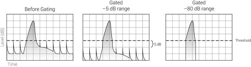
Figure 19.6 The range function of a gate. When the range is set to –5 dB, signals below the threshold are attenuated, but still heard. With large range, such as –80 dB, signals below the threshold become inaudible.
![]()
The range value can be expressed in either positive or negative values. Depending on the manufacturer, a gain attenuation of 40 dB might be expressed with a range of 40 or –40 dB. This book uses the negative notation. Small range denotes little effect (e.g., –5 dB), while large range denotes more effect (e.g., –80 dB).
Generally speaking, large range settings are more common in mixing. However, sometimes it is only a gentle attenuation we are after. One example would be gating vocals to reduce breath noises between phrases—removing breaths altogether can sound artificial, so these might only be attenuated. Another example involves reducing the room reverb captured on a recording.
![]()
The following tracks demonstrate different range settings on a gate. The larger the range, the less gated portions of the sound can be heard. Notice that it is only with a range of –20 dB or less that the gated material is easily audible.
- Track 19.10: Snare Range –60 dB
- Track 19.11: Snare Range –40 dB
- Track 19.12: Snare Range –30 dB
- Track 19.13: Snare Range –20 dB
- Track 19.14: Snare Range –10 dB
Plugin: McDSP Channel G
Attack and release
Attack controls how quickly the gate opens; release controls how quickly the gate closes. For example, with the range set to –80 dB, a closed gate would apply –80 dB of gain on the input signal. The attack determines how quickly these –80 dB rise to 0 dB when the gate opens, while the release determines how quickly the gain returns to –80 dB when the gate closes.
The response times on a gate are normally set in milliseconds. Attack times usually range between 0.010 ms (10 µs) and 100 ms. Release times are often within the 5–3,000 ms range. As with compressors, both the attack and release times determine the rate of gain change (how quickly gain reduction can rise or fall). For instance, a gate might define that response times are referenced to 10 dB of gain change. With an attack of 1 ms and a range of –10 dB, it will take 1 ms for the gate to fully open; but with –80 dB of range, it will take the gate 8 ms to open. The practical outcome of this is that the range affects the overall time it takes a gate to open and close—where appropriate, we can achieve faster attack and release times by dialing a smaller range. In turn, this promotes smaller range settings than a gate might offer—on a busy mix, a range of –40 dB could suffice to make signals below the threshold inaudible.
It is worth noting that both the attack and release controls have the opposite effect on dynamic envelopes to compressors. A longer attack on a gate means that less of the natural attack is retained; a longer release on a gate means that more of the natural decay is retained. Figure 19.7 illustrates this on a gated snare.

Figure 19.7 The effect of attack and release on a gated snare. The top row shows different attack times with no release; the drop in gain reduction is shown as a triangle above the graphs. We can see that the longer the attack is, the longer it takes gain reduction to drop and the less of the snare’s original attack is retained. A long attack setting causes gain reduction to drop so slowly that none of the signal is audible before the input drops below the threshold. The bottom row shows different release times with no attack; the rise in gain reduction is shown as a triangle above the graphs. We can see that the longer the release is, the slower the gate reduces the signal once it falls below the threshold, so more of the natural decay is audible.
On a gate: longer attack, less of the natural attack; longer release, more of the natural decay.
![]()
The source track used in the following tracks demonstrates different attack times on a snare. The threshold was set to –20 dB, the range to –60 dB, and the release to its minimum of 100 ms. Notice how the longer the gate’s attack is, the less of the snare’s natural attack is retained.
- Track 19.16: Snare Attack 10 ms
- Track 19.17: Snare Attack 1 ms
- Track 19.18: Snare Attack 5 ms
- Track 19.19: Snare Attack 10 ms
- Track 19.20: Snare Attack 50 ms
- Track 19.21: Snare Attack 100 ms
Another set of tracks with the same gate settings, only this time with attack fixed to its minimum of 10 µs and varying release times. The longer the release, the more of the natural decay is retained:
- Track 19.22: Snare Release 100 ms
- Track 19.23: Snare Release 300 ms
- Track 19.24: Snare Release 600 ms
- Track 19.25: Snare Release 900 ms
Plugin: McDSP Channel G
Snare: Toontrack EZdrummer
Using the same principle discussed in Chapter 17, very short attack and release times can cause audible clicks due to abrupt level changes. A steep level rise produced by fast attack generates high frequencies; the shorter the attack, the higher the frequency (Figure 17.30 illustrates the reason for this). The same applies to release, although the gate operation on the quiet signals below the threshold tends to be slightly less noticeable. Depending on the gated signal, fast response times might also alter the low and mid frequencies, which essentially means that a gate can affect any part of the frequency spectrum—a side effect we have to observe.
The attack setting has an extra weight when gating transients, especially those with low-frequency content such as kicks. Most of the kick’s character is in its very first cycle, with most of the impact gearing up at the beginning of this cycle. A gate is most likely to reshape this important part of the waveform—either with a short attack that produces sharp level changes or with a longer attack that reshapes the waveform and withholds the kick impact. One way or another, the kick’s tonality is very likely to change, with the lows, mids, and highs all likely to suffer. Ideally, we would like the attack to retain the original shape of the signal’s waveform, which is often only possible with look-ahead (discussed later). Figure 19.8 illustrates this.
Very short settings can also cause low-frequency distortion due to the gate operation within the cycles of a low-frequency waveform. Longer attack, release, or hold can rectify this issue. In the case of percussive performance, we must consider how the release and

Figure 19.8 A gated kick. The top track shows the original kick, and it is hard not to notice the dominant first cycle. The middle track shows the kick after gating with the settings shown on the Digidesign DigiRack Expander/Gate on the right. The attack was set as short as possible and the look-ahead was disabled. It is possible to see the partial loss of initial impact and the steep level climb caused by the gate opening, which generates high frequencies. The bottom track shows original kick after gating with the same settings, but with look-ahead enabled. You can see how the initial attack was not affected.
![]()
Track 19.26: Kick Source
The source kick track used in the next track.
Track 19.27: Kick Rising Attack
For the purpose of demonstration, the threshold of the gate in this track was set high at –15 dB. The attack was automated to rise from 10 µs to 24 ms. First, notice how the impact of the kick has completely disappeared. Then, notice how the click generated by the steep level change decreases in frequency as the attack is lengthened. Once the attack is long enough, it doesn’t generate a click but yields a drop in level (this track was not faded out).
Plugin: Digidesign DigiRack Expander/Gate Dyn 3 Kick: Toontrack EZdrummer
Track 19.28: Kickverb Release Click
The click generated when the gate closes is caused by the steep drop in level—the result of 0 ms release.
Track 19.29: Bass Source
This is the source track for the following sample.
Track 19.30: Bass LF Distortion
The extremely unflattering distortion in this track is the result of threshold at –14 dB, range of –60 dB, and 0 ms for all time constants. Although exaggerated in this track, distortion caused by super-fast time constants on a gate is usually as unflattering as this.
Plugin: Logic Noise Gate
hold settings, which affect the length of the sound, lock to the rhythmical feel of the track. In addition, we want the gate to fully close before the next hit arrives, or successive hits will be gated differently (due to variety in gain reduction during the attack phase).
One issue with the principal operation of gates is that we often want short attack, so more of the signal above the threshold passes through, and short release, so the signal below the threshold is attenuated quickly. These typical short settings are more obstructive for the many reasons explained above. We have to remember that in many cases, the attack and release are applied on large-scale gain changes, with a range of –60 dB or more. Compressors, conversely, often work on 20 dB or so, and moreover gain changes are not as steep due to the gradual development of the input signal. A gate has no such softening mechanism—it is either open or closed, and there is often quite some gain involved when toggling between the two.
The attack and release on a gate tend to be obstructive due to their typically short settings.
Short attack and release settings are not always appropriate, though. Longer times are often used when the gated instrument has long natural attack and release; for example, a synthesized pad that rises and falls in a gradual fashion. Short attack and release will simply trim the parts of the signal that ascend above or descend below the threshold. Long settings will keep some gradual sense for both the natural attack and decay.
Longer attack times might let us lower the threshold by a small amount. The reason for this is that false triggers will not be long enough to become audible. For example, a long attack in Figure 19.3 would allow the threshold to be slightly below the hi-hat peaks. Although the top of each hit will trigger the gate opening, the slow attack will mean the gate will not fully open by the time the hit drops below the threshold, potentially leaving these hits inaudible.
Hold
Once the signal has dropped below the threshold, the hold time determines how long the gate’s gain reduction is held unaltered. For example, if 8 dB of gain reduction is applied as the signal undershoots the threshold, a hold period of 2 seconds will mean 2 seconds with 8 dB of gain reduction. Once the hold period is completed, the release phase starts. Gates typically offer a hold period of between 0 and 5 seconds.
Hold often replaces release in the task of retaining the natural decay of an instrument. There are two reasons for this. First, we can see from Figure 19.7 that quite a long release setting is needed in order to keep the natural decay. Such a long release is not always practical since it might not end before the next time the signal overshoots the threshold. Second, having the release starting right as the signal drops below the threshold causes an escalated decay—the natural decay of a snare, for example, will be superimposed by the artificial descent caused by the release function. Using hold instead of release lets us keep the fall rate of the natural decay. The hold time can be made to match the interval between two hits, while some release is still used in order for the gate to close without audible clicks (Figure 19.9).
Hold can be used to retain the character of the natural decay.

Figure 19.9 The difference between release and hold. With release, the natural decay of the instrument is reshaped, which is not the case with hold. The short release after the hold period is applied to prevent clicks.
As with compressors, longer hold periods can reduce low-frequency distortion. Longer hold time can also reduce chattering, as the gate is held open while the signal rapidly leaps between the two sides of the threshold. In that sense, the hold facility provides a similar function to hysteresis, so when no hysteresis is offered, hold can be used instead. In addition, hold might be used to compensate for any look-ahead time that might be in force. For instance, if look-ahead is set to 10 ms, the gate will start closing 10 ms before the signal drops below the threshold. Setting a hold time of 10 ms will compensate for this early response.
![]()
The following two tracks demonstrate the use of hold to prevent chattering. The source track is identical to Track 19.7, with no hysteresis. A hold setting of 50 ms is nearly enough to prevent the chattering; 200 ms of hold rectifies it completely.
Track 19.31: Kickverb hold 50 ms
Track 19.32: Kickverb hold 200 ms
Track 19.33: Tom Source
The source track used for the following samples.
Track 19.34: Tom Short Hold Long Release
The gate is set with 50 ms of hold and 710 ms of release. The release reinforces the dropping level of the tom, accelerating its decay.
Track 19.35: Tom Long Hold Short Release
The gate is set with 710 ms of hold and 50 ms of release. Once the tom drops below the threshold (–17 dB), the hold function keeps the gate open, allowing its decay to pass through unaffected. Then, the release quickly closes the gate. The tom’s decay is retained here far better than in the previous track, but at the cost of some extra spill level.
Plugin: Logic Noise Gate
Look-ahead
This is perhaps the ultimate problem with gates: short attack results in clicks; long attack softens the natural attack and can even repress the beginning of words. Lower threshold? Cannot be done or spill will open the gate. Filter the side-chain? Helps a little. But there is a solution—look-ahead.
As with a compressor, look-ahead lets the side-chain examine the input signal slightly before processing takes place. This means that we can dial longer attack times, since the attack phase starts sooner. By the time the signal arrives at the gain stage, gain reduction has decreased to a degree that allows the leading edge of the signal to pass through the gate with no clicks or envelope reshaping. The very same principle applies to release—since the release phase starts shortly before the treated signal drops below the threshold, we can set longer release times. One of the prime benefits of look-ahead is that it allows longer attack and release times, which make the gate operation less obstructive.
Look-ahead makes the gate operation less obstructive.
A look-ahead function on an analog gate will introduce output delay. Software gates have no such issue, provided auto plugin delay compensation is active. Later, we will look at an extremely useful look-ahead trick that results in no delay with both analog and digital gates.
![]()
Track 19.36: Kick No Look Ahead
Using Track 19.26 as a source, the click is caused by a very short attack (10 µs, not automated in this track). The threshold is set to –20 dB and no look-ahead is involved.
Track 19.37: Kick with Look Ahead
By simply enabling look-ahead (2 ms), the click has disappeared and the full impact of the kick is maintained.
Plugin: Digidesign DigiRack Expander/Gate Dyn 3
Side-chain filters
Just like a compressor, some gates let us equalize the side-chain signal that triggers the gating. A classic example of how extremely helpful this is can be seen when gating a kick track in order to get rid of spillage, such as the hi-hats or snare. It goes without saying that both the hi-hats and snare have less energy on the lows than the kick. So we can filter the highs and mids content from the side-chain, leaving mostly the low-level energy of the kick. In turn, this lets us lower the threshold, so more of the original kick attack can be retained.
Key input
Gates, just like compressors, let us feed an external signal into the side-chain. On a compressor, the external source input is called external side-chain. On a gate, the same input is often called key input instead (to prevent confusion when a dynamic range processor offers both a compressor and a gate, and the side-chain of each can be fed from a different external source).
We can feed the key input with either a similar signal to the one being gated or a different signal altogether. In the case of the former, an example would involve a gate microphone— an additional microphone on a specific drum, which is later used in mixdown to feed a gate’s key input. A gate microphone has one role—capturing the drum with as little spill as possible. Thus, gate microphones (often dynamic/cardioid) are placed as close as possible to the drum skin and are not concerned with faithfully capturing the timbre of the drum. When we gate a snare, we feed the snare microphone into the gate input and the snare’s gate-mic into the key input. This way, we can dial lower threshold, achieve more accurate gating, and have more freedom with the different control settings. Gate microphones aside, sometimes a specific track will benefit from being gated in respect to a similar track. For example, a kick-out track is better gated with respect to the kick-in microphone, which would normally capture less spill (Figure 19.10).

Figure 19.10 Gating kick-out with relation to kick-in. This illustration shows a recording setup, although we usually do this during mixdown with the recorded tracks. The kick-in track is likely to incorporate less spill than the kick-out. While gating the kick-out, feeding the kick-in to the gate’s key input is likely to provide more musical gating. Also, the sound arrives at the kick-in microphone slightly before the kick-out microphone, providing a natural look-ahead. A gate-mic can replace the kick-in for other drums such as the snare.
Output level
Although not often provided, the output level control offers a similar functionality to a compressor’s makeup gain—boosting or attenuating the entire signal by a set number of dB.
Stereo link
The stereo link function on a gate is similar to that on a compressor—it ensures that both left and right channels are gated identically, so no image shifting occurs.
Meters
Some gates provide a gain reduction meter just like compressors. Some have two indicators—one lights up when the gate is open, one when the gate is closed. Some gates add an additional indicator that lights up during the attack, hold, and release phases, when the gate is neither fully open nor fully closed.
Applications
Removing noise
Noise can be introduced onto a recording in many ways. Tape media, microphones, preamps, any analog component, and A/D converters are just a few examples of systems that superimpose their inherent noise onto a signal. When a recording is carried out in a domestic facility, background noise is also often an issue. Essentially, any signal that ever roamed the analog domain includes some noise. Even purely digital signals, for example a bassline generated with a software instrument, can incorporate either quantization distortion or dither noise.
Luckily, modern technology enables cleaner recordings than in the past; so much of the noise on today’s recordings is inaudible. Generally speaking, if high-quality equipment is used, and used correctly, a gate for noise removal might not be needed at any stage of the mix. If, for example, the signal-to-noise ratio on a digital recording is 60 dB (noise level at –60 dBFS), chances are that the noise will not be a problem. Even higher noise levels might not be an issue since in many cases the wanted signal masks it. Noise tends to be more noticeable with sparse arrangements and during the quieter sections of a production—in both cases, there is less to mask it.
One thing worth considering is that noise can become more noticeable as the mix progresses. For example, after applying makeup gain on a compressor, the noise level would rise as well. Also, by boosting the highs of a specific track, the noise is likely to become more noticeable.
Even when the noise is audible, one has to ask: What is wrong with a little bit of noise? Many people associate the synthetic sound of digital systems with the lack of noise and distortion. In fact, some engineers deliberately add noise or distortion to a digitally clean recording in order to replicate some of the familiar analog idiosyncrasies. The noise in these cases might be similar to a tape hiss or even crackling vinyl. Nevertheless, other noises such as those generated by washing machines are a problem—they are unlikely to remind anyone of the familiar analog sound.
Some judgment has to be made as to what noise needs gating and what can be tolerated.
Another point is that our ears find varying noise levels (such as breathing) more disturbing than constant noise levels. This fact is taken into account in many noise reduction systems. We have to consider this when gating a noisy track—varying noise levels after gating might be more noticeable than the constant noise level before gating. Say, for example, we have a sparse arrangement with a noisy vocal track. The noise is likely to be masked or be less noticeable while the vocals are sung. The challenge is to make sure that the gate opening and closing does not cause noticeable noise variations. Once the vocal drops below the threshold and diminishes, a slow release can cause a noticeable descent in noise level. If the vocal is sent to a reverb emulator, this drop might be even more noticeable.
Removing spill
Much of today’s tracking is done using overdubs; these are less prone to spill, and mostly we deal with headphone leakage and the spill on the various drum tracks. Spill can result in four main problems:
- Impairing separation—ideally, we want each track to represent a single instrument or drum (room-mics and overheads are obvious exceptions). A snare track that also contains the hi-hats would make it hard to separate the two. For example, such a hybrid track would restrict independent panning of each drum, and in turn could cause a smeared stereo image on at least one of them.
- Comb filtering—the hi-hats on the snare track might not be phase-aligned with the hi-hats track or with the overheads. When the snare is mixed with either track, comb filtering is likely to impair the timbre of the hi-hats and give it a hollow, metallic, or phasing sound. Any instrument might suffer from loss of focus, impact, or timbre coloration if its intended track is mixed with its own spill on another track.
- Adding dirt—whenever an instrument is not playing, a spill on its track can produce unwanted sounds. Floor toms are notorious for producing rumble when the rest of the kit is played. Headphone spill might add unwanted noise during quiet sections.
- Interfering with processing—to give an example, a loud kick on a snare track might trigger compression and interfere with the snare compression. Brightening a tom track might also emphasize any hi-hat spill it includes.
This list suggests that spill should be removed whenever possible. On occasion, after removing the spill, we may find that bypassing the gate actually has a positive effect on the mix. The reasons for this are mostly unpredictable. Regardless, we must remove the spill first in order to learn whether its removal actually improves the mix. It is also worth remembering that processors added later in the mix, such as compressors and equalizers, could also have an effect on this. With that said, once the mix is in its final stages, it is worth trying to bypass spill gates, and see whether the mix changes for better or worse.
One of the main challenges with gating is keeping the timbre of the gated instrument. It has already been mentioned that a lower threshold setting would help in doing so. This task is made harder when the wanted signal and the spill are relatively close in levels, especially if they share the same frequency regions. Snare and hi-hats, kick and toms are potentially problematic pairs, especially if spill was not considered during microphone selection and placement. We may employ any possible gate facility in order to improve our gating. Side-chain equalization lets us attenuate the spill by attenuating its dominant frequencies, look-ahead lets us retain more of the natural attack, and hysteresis lets us keep more of the instrument’s natural decay. For exceptionally tricky gating tasks, it would be extremely beneficial to use at least one of these facilities, if not all of them.
One of the main challenges in gating is keeping the timbre of the instrument, mainly its natural attack and decay.
When gating drums, there is often a trade-off between the length of the natural decay and the amount of spill—the longer we retain the natural decay, the more spill will escape gating. The spill is often made louder by a compressor following the gate, and the instrument can become louder in the mix for short periods while the gate is open. For example, the hi-hats spill on a snare track might make them louder while the snare decays.
One solution to this involves ducking the intended hi-hats track in an opposite fashion to the snare’s gating, so while the open gate adds some hi-hats spill, the actual hi-hats track is attenuated. Another solution is decay reconstruction—the gate shortens much of the decay so no spill remains, and a reverb is employed to imitate the missing decay.
Reshaping dynamic envelopes
Just like compressors, gates are also employed to reshape the dynamic envelope of instruments, mainly of percussive ones. We can say that a compressor operates on a transient (once it overshoots the threshold) and on what comes shortly after it (due to the release function). A gate operates on both sides of the transient (essentially, the signal portion below the threshold). Yet, a gate might also affect the transient itself due to the attack function.
As per our discussion in Chapter 17, a part of adding punch is achieved by shortening the length of percussive instruments. Typically, the natural decay that we try to shorten is below the threshold, which makes gates a great tool for the job. It is a very old and common practice—you gate a percussive instrument, and with the gate release (and hold) you determine how punchy you want it. Just like with compressors, we must consider the rhythmical feel of the outcome of gating. As gates constrict the length of each hit, the overall result of gating percussive instruments tends to make them tighter in appearance. Figure 19.11 demonstrates this practice. The threshold is set to the base of the natural attack and above the natural decay. The range would normally be set moderate to large. The release and hold settings determine how quickly the natural attack is attenuated (with longer settings resulting in longer natural decay). If we only want to soften the natural decay, not shorten it altogether, we can use smaller range settings.
Gates are often employed to add punch to percussive instruments.

Figure 19.11 Adding punch to a percussive instrument using a gate. The threshold is set to the base of the natural attack and the range is set moderate to large. The release together with hold will determine how quickly the natural decay is attenuated and in turn the overall length of the hit.
We can also accent the natural attack, accent transients, revive transients, or reconstruct lost dynamics using a gate. This is normally done by setting the threshold somewhere along the transient and dialing a very small range so everything below the threshold is mildly attenuated. It is also possible to boost the output signal, so the transient is made louder than before but everything below the threshold returns to its original level. Figure 19.12 illustrates this.

Figure 19.12 A gate emphasizing the attack of a snare. The gate threshold is set halfway through the natural attack. After gating, both sides of the transient have been reduced in level, including the snare’s decay. If we boost the gate output, the material below the threshold returns to its original level, but the snare’s attack ends up louder in level compared to the signal before gating.
It is worth noting that the threshold in Figure 19.12 was set higher than the base of the natural attack. Had the threshold been set lower than that, the gate operation would most likely have altered the dynamic envelope of the snare in a drastic, unwanted way. Figure 19.13 illustrates why this specific application can be somewhat trickier to achieve with a gate than with a compressor. We’ve already said that a gate’s attack and release functions tend to be more obstructive due to their typically short settings. While on a gate we would dial both fast attack and release for this application, on a compressor we would dial longer, less obstructive settings. One outcome of this is that when gates are employed for this task, the results tend to be more jumpy than those of a compressor. For these reasons, the gate’s range is often kept as small as possible, and look-ahead is employed.

Figure 19.13 A gate reshaping destructively the dynamic envelope of a snare. Due to the low threshold setting, the release function has altered the dynamic envelope in a drastic way, resulting in a new shape that does not resemble the input signal.
![]()
Track 19.38: Kick Snare Source
The source track for the following samples, in which the snare is to be gated.
Track 19.39: Kick Snare Range –4 dB
The gate’s threshold was set to –36 dB, the attack to the minimum of 5 µs, hold to 30 ms, and release to 17 ms. The range was set to –4 dB, so the snare’s decay is only attenuated a little. Despite no gain compensation, the snare in this track has more profound attack and punch.
Track 19.40: Kick Snare Range –30 dB
With the same settings as in the previous track but –30 dB of range, the snare’s decay is removed. This can also translate into a more punchy sound that, despite sounding unnatural, can be suitable for some genres.
Track 19.41: Kick Snare Range Longer Hold
We can lengthen the hold parameter to determine the length of each hit. The settings in this track are identical to those in the previous track, only the hold is lengthened to 90 ms. Compare this track to track 19.38.
The kick in the previous four tracks is also gated, but only in order to get rid of some low-frequency tail:
Track 19.42: Kick No Gate Track
Track 19.43: Kick Gated
Plugin: Sonnox Oxford Dynamics
Drums: Toontrack EZdrummer
In practice
The problem with gates
What is being gated, and how, is largely determined by the threshold setting. Ideally, we would like the gated material to show few gating inconsistencies. This can be achieved if the static threshold setting always affects identical parts of the signal, which is often not the case. For example, if two tom hits vary in level, a gate would attenuate more of the quiet hit’s natural attack and decay. Snare hits might be roughly at the same level, but if at a specific section the drummer plays a crescendo, the first few quiet hits might be below the threshold, and therefore muted completely (in this specific case, we can bypass the gate momentarily).
Normally, we loop a specific section while setting the gate. Once happy with our settings, it is important to perform a run-through—playing the track while soloed, beginning to end, to ensure that the gate works as intended throughout the full track length. Even in the case of toms that only play occasionally, it is wise to listen from beginning to end (rather than jumping between the hits) to make sure that no false triggering occurs (for the most part of these run-throughs, we will hopefully enjoy the silence).
Traditionally, gates are placed before compressors since the compressor’s nature of reducing dynamic range makes gating a trickier affair. However, on a software mixer, it would not be considered odd practice to place a balancing compressor before the gate, so level inconsistencies are reduced before the signal is gated. The gate might still be followed by another compressor that has a different role, such as adding impact.
Gate alternatives: manual gating
Gating inconsistency is an outcome of varying levels, which are a natural part of a real performance. If we take drums, for example, it could be great having the ability to gate each hit with different settings, but automating a gate for such a purpose would be unwieldy. Fortunately, audio sequencers offer a gating alternative that lets us do exactly this, a practice we will call hereafter manual gating. To be sure, manual gating would not produce a characteristic effect like many gates do and can sometimes be senseless— treating 128 kick hits individually can be tedious. But with instruments such as toms, which involve fewer hits, individual treatment for each hit can be feasible. Manual gating can also work on vocals, electric guitars, and many other instruments. It usually takes more time to perform than standard gating, but it gives us more control over the final results.
When sensible, manual gating provides a powerful alternative to standard gating.
Essentially, manual gating is like offline gating that we can then tweak. It involves three main steps, which are demonstrated in Figure 19.14:
- strip silence;
- boundary adjustments; and
- fades.

Figure 19.14 Manual gating using strip silence. From top to bottom: the original three tom hits, after strip silence, after boundary adjustments, and after fades. Note that only the right boundary of the second region (third tom hit) and the different fade lengths for each region were adjusted. This screenshot makes use of four tracks to show each step at a time; normally, we perform all steps on the original track.
Strip silence is an offline process that removes quiet sections from audio regions. It works by splicing an audio region into smaller regions that contain the signals we wish to keep. Figure 19.15 shows the “Detect Silence” window of Cubase. Other audio sequencers provide parameters akin to the ones in this figure. The similarity to a gate is evident from the open and close threshold settings. A minimum time for “gate open” and “gate close” is also given, as well as pre- and post-roll times, which create pad margins before and after each splice. The pre-roll time is of great importance; without it, the process is likely to produce clicks, just like a normal gate with a very short attack would.

Figure 19.15 Cubase’s “Detect Silence” window. In this screenshot, the process is applied on three tom hits. Due to the close proximity of the first two, they end up within the same region. It is also evident that the decay of the third hit is being trimmed (but also some spill that is not visible in this illustration). It is worth remembering that the low-level decay being trimmed here might not be audible unless the tom is played in isolation. One way or another, we can adjust the region boundaries afterwards.
The main aim in the strip silence step is to divide the wanted signal into sensible regions. The exact boundaries of each region are less critical, since the next step involves adjusting each region’s boundaries individually. If we set the strip silence threshold and pre-roll time appropriately, modifications to the start of each region might not be required. The region’s end is adjusted to match the decay length we are after, while taking into account the level and amount of spill. The final step of manual gating involves fading in and out each region, which is similar in effect to the attack and release functions of a normal gate. We can set different fade lengths (attack and release) for each region and normally have control over the shape of each fade.
Gate alternatives: de-noisers
Another alternative to gates, when used to remove hiss or other kinds of noise, is the digital de-noiser (Figure 19.16). Most modern de-noisers need to be taught the nature of the noise to be removed. This is done by feeding pure noise to the de-noiser while in learn mode. Such pure noise is often available at the start and end of tracks. Feeding a de-noiser with anything but pure noise can result in a wired digital effect that might be justified in some creative (somewhat experimental) contexts. Generally, de-noisers do a better job than gates in removing noise and involve a quicker and easier setup. However, this is subject to the noise being of a consistent nature, for example the static hiss of analog components. De-noisers are not so good at reducing dynamic noise, such as headphone spill or street noise.

Figure 19.16 A de-noiser plugin, the Sonnox Oxford Denoise.
Tricks
Manual look-ahead
A look-ahead facility on a gate is invaluable. Most software gates provide it, but not all hardware units. Often the look-ahead time is fixed, and there might be a switch to bypass this feature altogether. Some gates also let us choose different look-ahead times, for example the MOTU MasterWorks gate in Figure 19.1 (the control below the plot). Whatever gate you use, the trick presented here provides a definitive look-ahead with any gate.
The idea of manual look-ahead is fairly simple. Say we gate a kick, we duplicate the kick track, we nudge the duplicate a few milliseconds back in time, and, instead of routing it to the mix bus, we feed it to the key input of the kick’s gate. Figure 19.17 illustrates this arrangement. One advantage of manual look-ahead is that we can set any look-ahead time we fancy. For example, by nudging the duplicate kick 20 ms backward, we get 20 ms of look-ahead time, and we can always nudge the duplicate back and forth (say, in 5 ms steps) to see which time works best. Typically, gates have look-ahead times within the 0–10 ms range, but in specific circumstances even 40 ms could be appropriate. Since the duplicate track is early in time compared with the kick track, the gate’s side-chain gets to see the kick a few milliseconds before processing it. The gate, whether software or hardware, has no output delay whatsoever—it is the key input signal being pulled back in time, not the gated kick being delayed.

Figure 19.17 Manual look-ahead in Pro Tools. The top track is the gated kick; the bottom is a duplicate nudged 20 ms backward. The duplicate output is routed to a bus named Kick SC, which feeds the side-chain of the McDSP Channel G.
Note that the Channel G plugin in Figure 19.17 is set so the key input signal is filtered (where hi-cut filter is applied to reduce spill). Had the gate not provided side-chain equalization, we could have simply inserted an equalizer on the duplicate track to achieve the same effect.
Virtually all audio sequencers and digital recorders let us duplicate a track and nudge it backward in time. But nudging is not exactly a part of any tape machine. Therefore, the arrangement would be very similar to the way analog gates implement look-ahead—a track would feed both the gate input and its key input, but the copy sent to gating would be delayed with a delay unit (obviously causing output delay).
![]()
While manual look-ahead is extremely useful with gates, it can be used with any other dynamic range processor that has an external side-chain facility—a compressor can benefit from this trick in the same way.
Kick-clicker
It has already been mentioned that short attack settings on a gate can produce an audible click, that the shorter the attack, the higher the byproduct frequency, and that the steep level rise can impair the timbre of the gated instrument, especially that of kicks. However, the resultant click caused by fast attack can also have a positive effect on kicks—it adds some definition. Indeed, sometimes gating a kick with a short attack improves its overall presence in the mix, although in most cases we have to compromise with some loss of impact. A simple trick can come to our rescue, enabling us to both keep the impact and add definition.
The arrangement is as follows: the original kick is gated so its leading edge is kept intact (often using look-ahead), while a duplicate track of the kick is gated to produce the click. The two are layered, and we can use the duplicate’s fader to determine how much click we want. We can also use the attack and threshold on the clicker-gate to alter the character of the click (instead of using an EQ). Normally, the hold and release are kept very short, so the clicker-gate only opens for a very short period, just to allow the click to pass through. The beauty of this arrangement is that, along with the click, some of the early impact also passes through the gate, resulting not only in improved definition, but also in some added power.
The kick-clicker trick works exceptionally well with sequenced music, where all the hits are of equal or very similar velocity. The problem with a recorded kick is that level variations between hits will produce clicks with changing character. There is an elegant way around this—placing a compressor before the clicker-gate.
![]()
Track 19.44: Kick-Clicker
This track is a gated version of Track 19.43. A threshold at –13 dB and the shortest release (5 µs) produce a click.
Track 19.45: Kick Snare with Kick-Clicker
This track is the result of layering the previous track at –9 dB with Track 19.41.
Plugin: Sonnox Oxford Dynamics
Drums: Toontrack EZdrummer
Adding sub-bass to a kick
This trick is used to add some low-energy power, or oomph, to kicks. Although some kicks already contain a hefty low-end, club music and genres such as drum ‘n’ bass and reggae can all benefit from some extra force, which some describe as chest power, others as LF wind. This trick is also sometimes used in rock mixes.
Figure 19.18 shows the layout of this trick. The idea is to add some low frequency whenever the kick hits. The low frequency is generated by an oscillator, which is gated in relation to the kick—whenever the kick hits, the gate opens to let the oscillator signal through. Figure 19.19 shows this setup in Logic.
Since it is pure power we are after, we do not want the oscillator to produce a recognizable pitch. Thus, a sine wave is used (being the only waveform that generates a pure frequency, with no harmonics to contribute to pitch recognition). The oscillator frequency is often set to 40 or 50 Hz, where 40 Hz would be more powerful, but fewer systems will be able to produce it faithfully. The higher the frequency, the more obvious its pitch becomes, thus frequencies above 50 Hz are rarely used.
To prevent a low-frequency hum that will constantly muddy the mix, the gate is set with maximum range so as to mute the oscillator whenever the kick is not playing. The attack is set short, but it is important to have it long enough to prevent clicks. The clicks produced by a gated low-frequency sine are most likely to vary in nature, as for each hit

Figure 19.18 Adding sub-bass to a kick. The oscillator is gated in relation to the kick. Every time the kick hits, the gate opens and lets the oscillator signal pass through. Both the kick and the oscillator are mixed.

Figure 19.19 Adding sub-bass to a kick in Logic. The sub-bass track is an aux track on which an oscillator is inserted to generate a 45 Hz sine wave. The oscillator is followed by a gate, which has its side-chain sourced from the kick track (Track 1).
the gate opens at random points along the waveform cycle (Figure 19.20). A very short release will also produce clicks, which can be even more disturbing as they are often delayed in respect to the kick’s attack. With the hold and release, we can set the length of each sub-bass beat. A short beat will simply reinforce the kick, and the longer it is made, the stronger the impact. One creative effect involves making the sub-bass longer than the kick itself, while setting the hold and release to create some noticeable decay (an effect mostly associated with drum ‘n’ bass tracks). That said, if the sub-bass beat is made too long, we could end up with a constant low-frequency content that will muddy the mix. Another creative approach is to make the sub-bass on the downbeat longer than all other beats, thereby emphasizing the downbeats.

Figure 19.20 Varying clicks on a sub-bass gated with fast attack. A 40 Hz sine wave was gated in relation to a kick. This illustration shows the post-gate outcome of four hits. The short attack produces a click, but, as the gate opens at random points along the cycle, a different click is produced for each hit.
The great challenge with sub-bass beats is sensibly balancing them on the frequency spectrum of the mix. Full-range monitors (or a subwoofer) and a controlled acoustic environment are requisite for this task. The process is usually this: we set the sub-bass level using the fader, then toggle between the full-range and the near-fields. As we toggle, we would like the relative instrument levels to remain as similar as possible, and by switching to the full-range speakers we only want to gain some extra power—it is an extension we are after, not an intrusive addition.
![]()
Track 19.46: Kick Snare No Sub-bass
The source track before the addition of sub-bass.
Track 19.47: Kick Snare With Sub-bass
50 Hz sub-bass is added to this track. The gate is set with its threshold to –40 dB, range to –80 dB, attack to 4 ms, hold to 150 ms, and release to 400 ms.
Track 19.48: Kick Snare Sub-bass Only
Only the sub-bass from the previous track.
Track 19.49: Sub-bass 30 ms Hold
A slightly tighter effect is achieved by shortening the hold parameter to 30 ms.
Track 19.50: Sub-bass 300 ms Hold
And a different effect is achieved by lengthening the hold parameter to 300 ms.
Track 19.51: Sub-bass Varying Clicks
This track demonstrates the varying clicks issue. The gate’s attack in this track was set to the minimum of 10 µs.
Plugin: Digidesign DigiRack Expander/Gate Dyn 3
Drums: Toontrack EZdrummer
The arrangement used for this trick is most often employed to add sub-bass to a kick. Another popular version of this trick involves adding filtered white noise to a snare in order to add some definition. We can just as easily add any signal to any other percussive instrument, whether for practical or creative reasons.
![]()
Track 19.52: Kick Snare with White Noise
This track is similar to Track 19.47 only with gated white noise triggered by the snare. The noise was treated with high-shelving attenuation and low-pass filtering. The gate settings are: threshold –40 dB, range –80 dB, attack 4 ms, hold 12 ms, and release 260 ms.
Plugin: Digidesign DigiRack Expander/Gate Dyn 3
Drums: Toontrack EZdrummer
Tighten bass to a kick
One way of looking at the previous trick is this: when the kick gets louder, the sub-bass gets louder. We had to mute the sub-bass at all other times to prevent low-frequency hum. How about keeping the same setup, but exchanging the oscillator for a bass guitar or a bassline? The bass will be muted apart from when the kick hits. First, muting the bass between kick hits will result in low-end deficiency (one mixing concept is that the kick provides low-end rhythmical power, while the bass fills the low-end gaps between the hits). Second, we lose important musical information as the bass often provides the harmony root. So this idea is not that great. But how about setting a small range on the gate so the bass is only attenuated by a small amount? The bass guitar will still be audible, but whenever the kick hits it will become slightly louder. This can be very useful if the bass is not extremely tight to the kick. Making the bass louder whenever the kick hits can give the impression that the bassist played the accents tight to the beat.