14
Panning
How stereo works
On 14 December 1931, Alan Dower Blumlein, then a researcher and engineer at EMI, applied for patent number 394,325, called “Improvements in and relating to Sound-transmission, Sound-recording and Sound-reproducing System.” This 22-page application outlined his ideas and vision to create a better sound reproduction system than the monophonic one used in those days. What Blumlein described as “binaural sound” is what we refer to today as stereo. His original concept was so far ahead of its time that many people could neither understand it nor realize its potential. The first stereo record was published in 1958—sixteen years after Blumlein’s mysterious death and six years after EMI’s patent rights had expired.
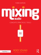
The term “binaural” denotes having or involving two ears. Our brain uses differences between the sound arriving at the left and the right ears to determine the localization of the sound source. The differences fit three criteria: amplitude, time (phase), and frequency. For example, if a sound is emitted from a trumpet placed to our right (Figure 14.1), the sound arriving at our right ear will be louder than that arriving at our left ear. This is due to the fact that the head absorbs and reflects some of the sound energy traveling to the left ear. As sound takes time to travel (approximately one foot per millisecond), it will also reach the left ear slightly later. Finally, since high frequencies are not very good at diffracting, they will not bend around our head like low frequencies, and less will reach the left ear.
In order to simulate the binaural differences that occur in nature, we can use a dummy head with microphones at its ears or use a computer to do the calculations instead.
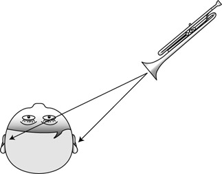
Figure 14.1 Sound produced from the right of the listener will have amplitude, time, and frequency differences between the left and right ears.
![]()
A demonstration of binaural processing. Using headphones, the congas should appear as if circling the head. Listening to this track through speakers would only make the congas shift between the right and left channels.
Plugin: Wave Arts Panorama
Percussion: Toontrack EZdrummer
(This is how 3D effects are implemented.) Either way, if we play such binaural material through headphones, we achieve a good sense of localization, with the ability to have sounds appearing as if coming from all around us, including the sides, behind, and even up and down. Essentially, we fool our brain by providing two distinct sounds with the same differences that sounds in nature involve.
Using two speakers instead of headphones does not achieve the same effect. In nature, the sound from a central source in front of the listener travels an equal path, thus reaching both ears at the same time, at the same amplitude and with the same frequency content. But a two-channel stereo setup does not have a center speaker, so in order to create a central image both speakers emit the same sound. Having no real center speaker, this central image is known as phantom center. If we could ensure that the sound from each speaker only arrived at the nearest ear, as in Figure 14.2a, the simulation would be perfect. But the sound from each speaker also arrives to the far ear and does so slightly later, while being quieter and having less high frequencies (Figure 14.2b). This late arrival confuses our brains and results in a slight smearing of the perceived sound image. This smearing effect can be demonstrated in every 5.1 studio by comparing the sound emitted solely from the center speaker (real center) and that emitted at equal levels from both the left and right speakers (phantom center). How unfocused the latter might be can be quite surprising, especially in poorly tuned surround studios.
The best stereo perception is experienced when a listener sits on the central plane between a correctly configured pair of speakers. Sitting in such a position is requisite for any mixing engineer, but most people listen to music in far less ideal locations. Although some of the stereo information is retained from the sweet spot, much of it is lost, especially when moving away from the central plane.
Figure 14.2 (a) A great stereo perception would be achieved if the sound from each channel reached its respective ear only. (b) In practice, sound from both speakers arrives at both ears, yielding a less accurate stereo image.
Pan controls
The pan pot
The first studio to install a stereo system was Abbey Road in London. Many other studios followed suit and soon enough all consoles had to accommodate this new feature. At first, consoles offered a three-state switch that could pan a mono signal either left, center, or right. This type of switch is evident in some old mixes where drums are panned to one extreme and bass to the other, and in all sorts of other panning strategies that are today only employed as a creative effect.
While working on Fantasia in the late 1930s, Walt Disney’s engineers wanted to create the effect of sound moving between the two sides of the screen. Following on from the work of Blumlein and Fletcher (the same Fletcher from the Fletcher–Munson curves, who also researched multichannel sound at Bell Labs), they found that as the level of one speaker continuously drops in relation to the other speaker, the image gradually shifts toward the louder speaker. Studio engineers could use this knowledge. They could feed the same signal into two channel strips, pan each to a different extreme, then attenuate one channel. Depending on the amount of attenuation, engineers could pan instruments across the whole stereo panorama (Figure 14.3). The problem was that, with the small consoles used back then, this was a huge waste of a channel. Thus, the panoramic potentiometer was invented, otherwise simply known as the pan pot.

Figure 14.3 Manual panning. The same track is sent to two channels, each panned to a different mix extreme. When the signal that travels to one speaker is attenuated, the resultant image shifts to the other speaker.
A pan pot does something very similar to the setup in Figure 14.3. It splits a mono signal to left and right channels, and attenuates one of the channels by a certain amount. Effectively, this alters the relative level between the two speakers. Figure 14.4 illustrates what happens inside a pan pot. Panning something to one speaker only requires complete attenuation of the opposite channel. Center panning is achieved by sending the signal at equal levels to both speakers.
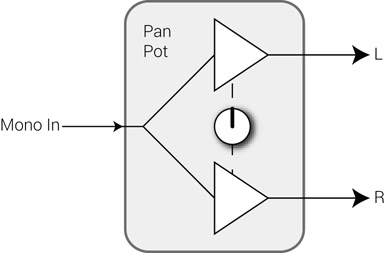
Figure 14.4 Inside a pan pot. The signal is split and each copy is sent to a gain control. The pot itself only controls the amount of attenuation applied on one channel or the other.
The pan clock
Often hours are used to describe the position of a pan pot. Although no convention exists, often the lingo involves hours ranging from 7:00 to 17:00, with 7:00 being the left extreme (also known as hard-left), 12:00 being center, and 17:00 being the right extreme (hard-right). Some use a 12-hour clock, representing 17:00 as 5:00, but for clarity the 24-hour format will be used in this text. Also, some call the center dead center; in this text, the term center signifies 12:00, and any panning position around it will be referred to as “around the center” (or “slightly off-center”).
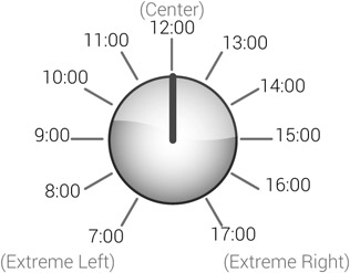
Figure 14.5 The pan clock.
Different software sequencers use different numeric scales to represent pan positions. Pro Tools and Cubase use a 201-step scale, while Digital Performer and Logic use the MIDI-based 128-step scale. Where hours might appear between the two speakers, and their equivalent values on the numeric scales, is shown in Figure 14.6.
![]()
Track 14.2: Pan Clock
This track involves 11 pink noise bursts, each panned to a different hour starting from hard-left (7:00).
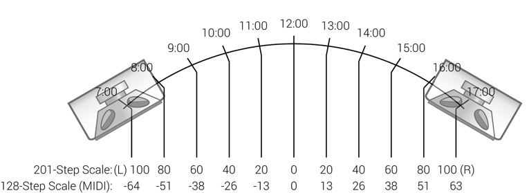
Figure 14.6 The rough position of the hours on the stereo panorama, and the hour equivalent numeric values on the 201-step and 128-step scales.
Panning laws
Not all pan pots behave the same. Depending on the pan law, the signal level might rise, remain constant, or drop as we twiddle the pot from the extremes toward the center. Just to complicate things, the panning behavior is different in stereo and mono. A console usually offers one pan law for all of its pan pots, although some in-line desks have two different pan laws—one for the channel path and another for the monitor path. Some applications let the user choose the pan law used in the software mixer (Figure 14.7). In these applications, the choice of pan law is done per project and not globally for the system (to keep backward compatibility). Changing the pan law halfway through a mix would alter the relative levels between instruments, so a choice must be made before mixing commences.

Figure 14.7 The pan law settings in (a) Cubase and (b) Logic.
There are two main principles to be aware of in panning law. First, acoustics has it that if two speakers emit the same signal at the same level, a listener on the central plane will perceive a 3 dB boost compared with what each speaker produces. For example, if two speakers emit 80 dBSPL each, the perceived loudness will be 83 dBSPL. The second principle is concerned with how mono is achieved. When two channels are summed to mono, half the level of each is sent to both. For example, with a signal panned hard-left, the left speaker might produce 80 dBSPL and the right speaker 0 dBSPL. Half the level is approximately –6 dB, so when summed to mono each speaker will produce 74 dBSPL. Based on the first principle, the perceived loudness in this case will be 77 dBSPL. We can see from this example that if a signal panned to one extreme is played in mono, it drops by 3 dB. For centrally panned signals, mono summation makes no difference— half the level of each channel sent to both channels results in exactly the same level on both.
Thus, the level of centrally panned signals remains consistent whether played in stereo or mono. The fact that when summed to mono the center mix-image remains unaffected and the extremes drop by 3 dB is not such a bad thing if we consider that most of the important instruments are panned center.
When summed to mono, the center image remains at the same level while the extremes drop by 3 dB.
The four common pan laws, –0, –3, –4.5, and –6 dB, are presented below for both stereo and mono. Before delving into each pan law, it is worth understanding, as mixing engineers, what it is we really care about. Depending on the pan law, mix levels might change as we pan. We generally do not want this to happen while we mix, as each pan move might call for subsequent fader adjustments. Since we mix in stereo, our only true concern is for levels to stay uniform as we pan across in stereo. Once the mix is bounced, the pan law is locked—the level balance printed on the master is determined and final.
![]()
How different laws behave in mono is of great importance in radio drama—signals panned from one extreme to another (for instance, a character crossing the stage) will be perceived differently on stereo and mono receivers.
Figure 14.8 illustrates how the perceived level varies for different pan positions with the 0 dB pan law. Pan pots of this kind do not drop the level of centrally panned signals. A signal panned hard-left might cause an 80 dBSPL radiation from the left speaker. If the signal is then panned center, both speakers will produce 80 dBSPL, which results in a 3 dB increase in perceived loudness. An instrument will rise in level as we pan it from either extreme toward the center (in other words, the instrument level will drop as we pan from the center outward). While panning from left to right in stereo, an instrument will have a 3 dB center boost. In mono, which is not of much interest to us, the standard 3 dB extremes drop happens, and while panning from left to right an instrument will experience a 6 dB center boost.
The –3 dB pan law (Figure 14.9) compensates for the 3 dB center boost that occurs with the 0 dB law. Centrally panned signals on pots of this kind are sent to each speaker at –3 dB compared with the level of a signal panned to either extreme. 80 dBSPL from one speaker for a signal panned hard-left will become 77 dBSPL from each speaker when the signal is panned center. This is a total perceived loudness of 80 dBSPL. When panning from left to right in stereo, signals remain at the same level. This is highly desirable while mixing, as pan adjustments rarely bring about the need for subsequent fader adjustments.
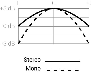
Figure 14.8 The perceived loudness of the 0 dB pan law.

Figure 14.9 The perceived loudness of the –3 dB pan law.
With the –3 dB pan law, signals panned from left to right have a uniform level in stereo, but in mono the perceived level has a 3 dB center boost. For mono-critical applications, the –6 dB law in Figure 14.10 is used. It provides a uniform level in mono, but a 3 dB center dip in stereo. Similarly to the 0 dB law, the –6 dB law is not recommended for stereo mixing, as fader adjustments might be needed after panning. Another pan law, the –4.5 dB, is a compromise between the –3 and –6 dB laws. In stereo, there is a 1.5 dB center dip, while in mono there is a 1.5 dB center boost (Figure 14.11). While neither in stereo nor in mono, the signal level is consistent as it is panned across; the maximum error is 1.5 dB and not 3 dB, as with the –6 and –3 dB laws.
Other variables might affect the choice of pan law. The first principle we discussed tells us that the power summation of two speakers produces a 3 dB increase on the central plane. In practice, the resultant loudness increase in less reverberant rooms might be 6 dB, but for low frequencies only. Having a low-frequency boost of 6 dB and a high-frequency boost of only 3 dB makes the –4.5 dB law a reasonable choice. Another issue is based on the assumption that most masking occurs in the central area, which means that panning instruments to the sides can result in an apparent loudness increase. The –2.5 dB pan law has a subtle +0.5 dB center boost to compensate for such a phenomenon. (For most of its history, Pro Tools’ pan pots used the –2.5 dB law; only recently other pan laws became available.) When a pan law choice is available, experiments can help us determine which pan law brings about uniform levels as sounds are panned across. The –3 dB law is very likely to be what we are after.

Figure 14.10 The perceived loudness of the –6 dB pan law.

Figure 14.11 The perceived loudness of the –4.5 dB pan law.
The –3 dB pan law is generally the best option for stereo mixing.
![]()
The following tracks demonstrate the different pan laws. Pink noise sweeps across the stereo panorama, and for each pan law two versions are produced (stereo and mono) and then bounced. Perhaps the most important thing to observe is how the level varies on the stereo versions as the noise is swept between the center and the extremes
- Track 14.3: Pan Law 0 dB Stereo
- Track 14.4: Pan Law 0 dB Mono
- Track 14.5: Pan Law –3 dB Stereo
- Track 14.6: Pan Law –3 dB Mono
- Track 14.7: Pan Law –4–5 dB Stereo
- Track 14.8: Pan Law –4–5 dB Mono
- Track 14.9: Pan Law –6 dB Stereo
- Track 14.10: Pan Law –6 dB Mono
The balance pot
Unlike the pan pot, the input to a balance pot is stereo, as can be seen in Figure 14.12. The two input channels each pass through a separate gain stage before being routed to the stereo output. The pot position determines the amount of attenuation applied on each channel. It is important to note that a balance pot never crossfeeds the input signal from one channel to the output of another. This results in a serious mixing limitation—the image of the input stereo signal is tied to at least one extreme. This is illustrated in Figure 14.14. We can narrow the stereo width of the input signal, but we cannot set it free from ending at one extreme.
In order to narrow the width of a stereo signal and place it freely across the stereo panorama, two pan pots are required (Figure 14.13c). Unfortunately, not all software mixers provide a dual-mono control for stereo tracks. Applications such as Logic only provide a balance control, and users need to load a plugin in order to place stereo signals freely across the stereo panorama (Figure 14.14).
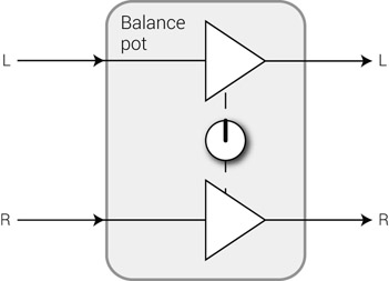
Figure 14.12 Inside a balance pot. Both the left and right inputs pass through separate gain stages. But the input from one channel never blends into the output of the other.
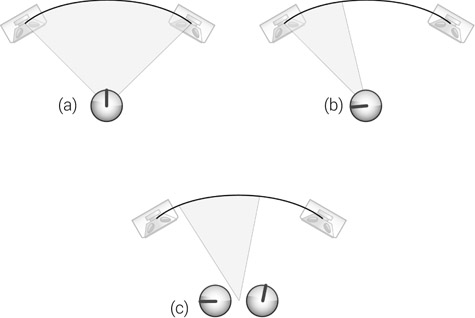
Figure 14.13 Both (a) and (b) show the resultant image of a specific balance position. As can be seen in (b), when the balance pot is turned left, the span of the resultant stereo image narrows but remains in the extreme of the stereo panorama. (c) If we need to pan anything so the span of the stereo image does not remain in the extremes, we need two pan pots instead of a single balance pot.

Figure 14.14 (a) Logic only offers balance control for stereo tracks. More control over stereo image can be achieved with the help of the direction mixer plugin. (b) Pro Tools offers dual-mono pan control for stereo tracks, which provides full functionality for any stereo imaging task.
![]()
Track 14.11: Balance Stereo Delay
This track involves a synth sent to a stereo delay.
Track 14.12: Balance Hard-left
The balance pot on the delay return is panned hard-left. As a result, the right channel of the delay is lost.
Track 14.13: Balance Hard-right
The balance pot on the delay return is panned hard-right. As a result, the left channel of the delay is lost.
Track 14.14: Balance No Can Do
Instead of using a balance pot on the delay return, a dual-pan control is employed. The left and right channels are panned to 10:00 and 14:00, respectively, narrowing the echoes toward the center. No balance control can achieve this, alas.
Plugin: PSP 84
Types of track
A single-instrument recording can involve more than one track. Raw tracks can be classified like so:
- Mono
- Stereo:
- – Acoustic:
- ◦ Coincident pair (XY)
- ◦ Spaced pair (AB)
- ◦ Near-coincident pair
- – Electronic
- – Acoustic:
- Multiple mono
Mono tracks
A single instrument, a single take, a single track. A mono track can be panned anywhere across the stereo panorama. The main problem with a dry mono track is that it provides no spatial cue. Only in an anechoic chamber will signals arrive at our ears without some room response—without some space being noted. When a dry mono track is placed untreated, it can appear foreign to the depth and ambiance aspects of the mix, and can appear frontal. A reverb emulator, or other spatial effect, is commonly employed in order to blend mono tracks into the spatial field of the mix. Even a tiny amount of ambiance reverb can do the job. A real problem can arise when a mono track includes some room or artificial reverb. The monophonic reverb is unlikely to mix well with the stereo reverb of the mix ambiance. Sending the track, with its embedded reverb, to the ambiance reverb might not be wise—a reverb of a reverb seldom makes any spatial sense.
Mono tracks often benefit from the addition of some spatial effect that blends them into the ambiance of the mix.
![]()
Track 14.15: Drum Loop
The loop under discussion in the following two tracks.
Track 14.16: Drum Loop Dry
When the drum loop is mixed dry, it can appear foreign to the mix—it is focused and positioned at the very front of the sound stage.
Track 14.17: Drum Loop with Reverb
By adding some reverb, the drum loop blends into the mix better, and it is not as distinguishable as in the previous track.
Plugin: Audio Ease Altiverb
Stereo pairs
A stereo pair track denotes a pair of mono tracks; each represents one of two microphones arranged in an established stereo miking technique. The two microphones are positioned in a way that will cause amplitude and time differences between the signals captured by each microphone. When the microphones are panned to the opposite extremes, the differences between them result in spatial reproduction. Stereo miking techniques are divided into three families: coincident pair, spaced pair, and near-coincident pair. While mostly a recording topic, each technique affects how we mix the given tracks.
The coincident pair technique, also known as XY, is based on two microphones angled apart with their diaphragms nearly touching. All but sounds arriving from the center will present different amplitude on each microphone. Because of the close proximity of the diaphragms, phase differences are disregarded. Due to the phase similarity between the two microphones, this family is known to provide the best mono-compatibility. The two tracks can be summed internally without causing noticeable comb filtering, and thus the two tracks can be panned inward from the extremes. This is often done in order to narrow the image width of an instrument, like with drum overheads.
Coincident pair gives the best mono-compatibility, which allows us to narrow the image of the stereo source during mixdown.
The coincident pair family includes stereo miking techniques such as Blumlein and MS (both devised by Alan Blumlein) or Power-thrust (hyper-cardioids at 110°). Of all these techniques, MS (mid-side) is most worthy of discussion, as it requires a special decoding matrix. The technique is based on a directional microphone facing the sound source (M) and a bidirectional polar pattern picking up the sides (S). Only two tracks are recorded, but on a desk these are decoded using three channels. The M is routed to one channel panned center. The S is routed to two oppositely panned channels, one of which is phase-inverted (Figure 14.15). The relative level of S determines the amount of reverberation and the stereo spread of the source in the mix.
![]()
More on MS in Chapter 27.
The spaced pair technique is also known as AB (often incorrectly titled XY). The arrangement of a spaced pair involves two microphones spaced a few feet apart; as a result of this distance, phase differences do occur. The microphones are usually omnidirectional so amplitude differences can be disregarded. Due to the phase differences between the two microphones, this technique is characterized by increased spaciousness and vague imaging. However, the same phase differences mean that this technique is not monocompatible. Any inward panning of the two microphones might result in noticeable comb filtering, sometimes forcing the two microphone tracks to be panned to the opposite extremes.
The coincident pair family is based on amplitude differences, while the spaced pair family is based on phase differences. The near-coincident family is a marriage of both—two microphones are angled and spaced, but only a few inches apart. The phase differences of a near-coincident recording do not present the same mono-compatibility as a coincident pair, but the differences aren’t as profound as with a spaced pair. Panning the two microphones to anywhere but the extremes can result in some degree of comb filtering, which may or may not be noticeable.

Figure 14.15 The MS technique. The M is routed to one channel panned center. The S is routed to two oppositely panned channels, one of which is phase-inverted.
In addition to the acoustic stereo pair, we can also get a stereo recording of a synthesizer or other electronic instrument. Whether or not the image of these can be narrowed can only be determined through experiment. But it is worth knowing that, despite having a stereo output, some of these devices are monophonic inside. The stereo size these devices produce might be achieved by having the pure monophonic output on the left channel and a processed version of it on the right channel. This is known as pseudo-stereo. When the stereo effect fails to blend into the mix, we can always abandon the processed channel and apply our own effect on the pure monophonic signal.
Multiple mono tracks
Multiple mono tracks are those that represent the same take of the same instrument, but do not involve an established stereo miking technique. Often each track captures a different timbre component of the sound source, so during mixdown we can shape the instrument sound using faders rather than processors. Some of these complementary tracks would be panned to different positions, most likely to the two extremes. An example would be two acoustic guitar tracks—soundhole and neck.
More often, though, these complementary tracks are panned to the same position, a practice that requires them to be in phase with one another. Examples include snare-top and snare-bottom, bass-mic and bass-direct, or three microphones used to capture the full timbre of a double bass. However, identical panning positions are not obligatory. When appropriate, the tracks can be panned to different positions, which will widen and blur the stereo image of the instrument. For instance, we can achieve such a blurry, wide snare image by panning the snare-top and snare-bottom differently. The effect can be made subtler if one of the tracks is attenuated. This effect can also be achieved artificially by panning a duplicate of a mono track to a different position, while generously altering its tonal character.
![]()
Track 14.18: Snare Top Bot Same
In this track, the snare-top and snare-bottom microphones are panned to the same position. The snare image is not perfectly focused due to the overheads and room-mic, but its stereo position can easily be pointed out.
Track 14.19: Snare Top Bot Mirrored
The snare-top is panned to the same position as in the previous track, but the snare-bottom is panned to the opposite side. This results in a less focused snare image, and an exact position is harder to identify.
Drums: Toontrack EZdrummer
Just as not all the songs recorded for an album are actually used, not all multiple mono tracks must be used. Sometimes using both bass-mic and bass-direct calls for treating each individually and then both collectively—this might involve two equalizers, three compressors, and a control group. Using one track only might not only be easier, but can also fall perfectly into the requirements of the mix. In the case of guitar-hole and guitarneck tracks, sometimes excluding one track and adding reverb to the other works better than mixing both tracks.
Combinations
With some recordings, such as drums or orchestral, we get a blend of different types of track; for instance, stereo overheads, multiple mono kick, and mono toms. In such cases, the stereo pair provides a reference image to the location of its constitutes. The respective mono tracks are often panned to the same position. For example, if the snare appears to come from 11:00 on the overheads, the snare track might be panned to that position. Again, this is not a hard-and-fast rule—different panning will result in wider, less focused images, which is sometimes sought (Figure 14.16).

Figure 14.16 The stereo image of a snare, depending on how its mono track is panned compared to the overheads image. (a) The snare is panned to the same position as it appears in the overheads stereo image, resulting in an overall focused image for the snare. (b) A snare panned far away from its overhead position will have a wider, unfocused overall stereo image, which is sometimes desired.
Panning techniques
An initial panning plan can be drawn just by looking at the track sheet. The nature of each track will usually hint at its rough panning position in the mix. The following is an example of an initial panning plan for a simple rock production:
- Overheads—70% wide around the center. Audience view.
- Kick—center.
- Snare—to the same location as it appears on the overheads.
- Snare reverb—40% wide, around the snare position.
- Tom 1—14:00.
- Tom 2—13:00.
- Tom 3—10:00.
- Bass—center.
- Vocals—center or maybe slightly off-center to the left.
- Power guitar I—hard-left (+Haas trick).
- Power guitar II—hard-right (+Haas trick).
- Flutes—halfway toward the extremes.
- Ambiance reverb—100% stereo width.
Plans are never successful until executed. Clearly, the above arrangement will not be suitable for all productions; it is just a possible starting point. A calculated approach, however, can backfire—different panning schemes can project very different feels, sizes, and power. In complex arrangements, experiments may be a necessity, and part of our role is to explore, discover, and reflect on different panning strategies.
Panning schemes can have a profound effect on the mix.
As the mix progresses and elements are added, we revisit the pans. Sometimes even small alterations result in big improvements—just shut your eyes and inch it until it latches into place. As already mentioned, panning alterations are sometimes part of the very last refinements of a mix.
Panning and masking
We already know that internal summing is less forgiving compared with acoustic summing. When two instruments are panned center, their internal summing accents any masking interaction between them. However, if each is panned to a different extreme, they are summed acoustically, which makes masking interaction less harmful. As a result, panning instruments toward the extremes also increases their definition. On the very same basis, masking is more dominant when two fighting instruments are panned to the same side of the panorama; mirroring one of them (e.g., from 15:00 to 9:00) can improve the definition of both.
The sound stage
Essentially, the stereo panorama pertain the horizontal plane of the imaginary sound stage. One of the main roles of pan pots is to determine where instruments are positioned on that stage. Just like on a real stage, listeners expect to find the most important instrument in the center of the mix—be it the vocalist or the trumpet player. Also, if we imagine a five-piece rock band on a big festival stage, it is unlikely that the two guitarists will stand on the stage edges; it is more likely that each will be somewhere halfway along each side. Many more examples can be given, but contemporary music is not always mixed to the full realistic extent of a live performance—if the guitars sound better when panned each to a different extreme, one would be a fool not to pan them that way. The visual sound stage is a guide often more suitable for natural mixes.
Low-frequency instruments, notably the bass and kick, are usually panned center. One reason is that low-frequency reproduction demands much more power than the reproduction of high frequencies. Panning low frequencies off-center will cause uneven power consumption between the two channels, which can have many downgrading consequences on the combined stereo response. The way vinyls are cut is another reason. What’s more, panning low-frequency instruments to the sides is somewhat pointless since low frequencies give very little directional cue (hence subwoofers can be positioned off the central plane). Yet it is worth remembering that both kicks and basses have important content in their mids as well.
Having both the most important and the low-frequency instruments panned center makes it inevitably the busiest area of most mixes, and where most masking happens. No panning police will arrest you for not panning the most important instruments dead center. Lead vocals, for example, can be panned slightly off-center; sometimes even the bass and kick are panned that way. Most listeners do not listen on the central plane anyway, and even if they do they are unlikely to recognize these subtle panning shifts.
The center is usually the busiest area in the mix. Instruments that would usually be panned center can be panned slightly off-center.
![]()
Track 14.20: Vocal Center
The vocal on this track is panned center (12:00).
Track 14.21: Vocal 1230
The slightly off-center (12:30) panning of the vocal in this track can easily go unnoticed, especially if the track is not compared to the previous one.
Track 14.22: Vocal 1300
The appreciation of the vocal panning in this track is dependent on the width of the monitoring setup. While mixing engineers with a wide stereo setup could find this off-center panning disturbing, normal listeners could easily fail to notice the off-center vocals.
Track 14.23: Vocal 1400
With the vocal panned 14:00, it is hard to overlook the off-center image of the vocal. Both engineers using a narrow stereo setup and normal listeners could find this panning scheme disturbing.
Another important area of the mix is the extremes. We have said already that over-panning to the extremes can result in mixes that have busy extremes and center but nothing in between; these are known as W-mixes. W-mixes are the outcome of the tendency to pan every stereo signal and every pair of mono instruments to the extremes. While it could be beneficial to pan overheads, stereo effects, or a pair of mono guitars that way, most mixes will benefit from a stereo spread balance, where mix elements are panned to fill the sound stage.
Not all stereo elements and mono pairs should be panned to the extremes.
It is a common practice in surround film-mixing that the voice of an actor standing behind the camera is still panned to the front speakers. Had it come from the rear, viewers would notice the existence of the rear speakers, which might distract them from the visual experience. As a general rule, cinema sound should accompany the visual but never draw too much attention on its own—you should feel as if part of the scene, but should not notice how this is done technically. The same principal applies with music mixing; the listener’s realization that two distinct speakers are involved in the production of a sonic experience can distract from the spatial illusion. Highly creative panning techniques should be used sparingly and only when appropriate.
Another fact worth remembering is that the center of the mix is the least-focused area (due to the late arrival of sound from both speakers to the respective far ear), while the extremes provide the most-focused area (as only one speaker generates the sound in true mono). Consequently, as instruments are panned toward the extremes, they become more focused. Combined with the curved nature of the mix front line, these instruments can also appear closer. This implies that the more an instrument is panned toward the extremes, the more it might benefit from the addition of a spatial effect—especially in the case of mono tracks.
The extremes = more focus, more definition, closer image.
![]()
When comparing the following tracks, the drum loop should appear closer and more distinct and focused when panned to the right extreme:
Track 14.24: Drum Loop Panned Center
Track 14.25: Drum Loop Panned Hard-right
As discussed in Chapter 7, one of the main mixing objectives when it comes to the stereo domain is balance. Both level and frequency balance are our main concerns. The offcenter panning of individual instruments is guided by this objective, and rough symmetry is often sought. One guitar to this side, another guitar to the other; a shaker to this side, a tambourine to the other; first vocal harmony at 11:00, the second at 13:00. A stereo balance relies on both instrumentation and recordings. “What instrument can we record that complements a shaker?” or “Shall we double-track the shaker?” are questions that should be asked before the mixdown stage. When an off-center track creates imbalance that no other track can repair, mixing engineers often utilize stereo effects, for example by sending a delayed echo to the opposite of a dry instrument (while perhaps altering its tonality).
We can also associate stereo balance with performance. Say 16th notes are played on the hi-hats and there are two guitars—one plays a 16th-note arpeggio, the other half-notes.
Panning the hi-hats and the arpeggio guitar to opposite sides will create rhythmical balance. But panning the hi-hats and the arpeggio guitar to the same side and the halfnotes guitar to the other will result in one extreme being rhythmically faster than the other. Subsequently, this will also affect the stereo balance between the two sides of the stereo panorama.
While balance is a general stereo objective, a perfectly stereo-balanced mix is essentially a mono mix. There is always a margin for some degree of disparity. If we take a drum kit, for example, with its hi-hats and floor tom on opposite sides, imbalance is inevitable. But if a tambourine also forms part of the arrangement, it would make more sense to pan it opposite the hi-hats. As per our axiom that “percussives weigh less,” sustained performance is more of a factor when it comes to stereo balance.
Effect panning
Stereo effects can be panned in various ways. The panning choice is mostly based on two aspects: width and center position. An ambiance reverb is one type of stereo effect that can benefit from full-width panning, especially when natural results and a wide sound stage are sought. But reverbs and delay lines used for creative purposes can benefit from a narrower image and off-center position. A classic example is the snare reverb, which is often different from the reverbs used for ambiance (or from the ambiance on the recording). When panned to the extremes, the wide snare reverb might compete with the ambiance and interfere with the spatial effect the latter provides. Combined, it might sound like the mix took place in a hall, while the snare was in a bathroom. Narrowing the reverb width will give a clear cue that it is not part of the general ambiance, but only an effect linked to the snare. This also promotes separation.
Matching the center of the snare and its reverb will emphasize this relationship. A mix with a snare panned to 11:00 might benefit from the snare reverb being panned around it, say 10:00 to 12:00. Narrowing the width of a stereo effect can also be beneficial with stereo delays. The combination of centrally panned vocals with hard-panned echoes makes the echoes noticeable, spatially random, and distant from their parent. To make the effect more subtle and focused we can pan the echoes inward toward the location of the vocals.
![]()
Tracks 22.38–22.40 in Chapter 22 demonstrate various stereo delay-panning techniques. Tracks 24.86–24.93 in Chapter 24 demonstrate various reverb-panning techniques.
Mono effects can benefit from the opposite way of thinking. The closer the effect is to its parent instrument, the less noticeable it will be, and we miss an opportunity to balance the stereo panorama. An example could be a mono delay applied on hi-hats. If the delay is panned to the same position as the hi-hats, the two are likely to collide. Panning the delay to the opposite side will increase the definition of both, while enriching the stereo panorama. One of the world’s most famous delay lines is said to have been created by accident when Giorgio Moroder panned a bassline to one speaker and its delay to the other. This effect, which originally appeared on Donna Summer’s “I Feel Love,” has been popular ever since, and can be heard on countless dance mixes.
![]()
As with “I Feel Love,” the bassline (8th-notes sequence) and the hats are panned hard-left. The 16th-note delays of both the bassline and hats are panned hard-right.
Track 14.27: Moroder No Delay
Same as the previous track but without the delay.
Track 14.28: Moroder Delay Only
In this track, the source bassline and the hats are muted, but not their delay. The delay is evidently a 16th-note behind the main beat.
Track 14.29: Moroder All Center
This is the result of panning all tracks, including the delay, to the same position. The effect is distinct from that on Track 14.26.
Plugin: PSP 84
Beyond pan pots
Autopanners
An autopanner pans audio back and forth between the left and right sides of the stereo panorama in a cyclical way. The operation of an autopanner might involve these parameters:
- Rate—when defined in Hz, determines the number of cycles per second; each cycle consisting of the audio being panned from the center to one extreme, to the other, and back to the center. Alternatively, the duration of a cycle might be defined in a tempo-related unit, such as a bar or half-note. With slow rate (roughly below 1 Hz), the left and right movement is clearly recognizable. This recognition is lost with higher rates, where the effect resembles a Leslie cabinet.
- Depth—defines in percentage how far toward the extreme the signal will be panned. With 100%, the varying panning position will reach the extremes; 50% halfway to the extremes; and so forth. The higher the depth setting, the more apparent the effect.
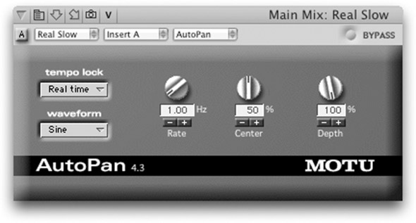
Figure 14.17 The MOTU AutoPan plugin.
- Waveform—defines the shape of the pan modulation. A sine wave will vary the position between left and right in a sinusoidal way. A square wave will make the audio jump between the two sides.
- Center—defines the center position of the modulation. With the center set halfway to the left extreme, it is possible for the audio to only drift back and forth between the center and the left extreme.
![]()
Track 14.30: Beat Source
The source track used for the following tracks.
Track 14.31: Beat Autopan Tri Depth 100
Triangle waveform modulation, 100 percent depth, rate is tempo-synced to one bar (center, as with all other samples here, is set to 50 percent, which is 12:00).
Track 14.32: Beat Autopan Sine Depth 100
Sine waveform, 100 percent depth, rate is tempo-synced to one bar.
Track 14.33: Beat Autopan Sine Depth 50
Sine waveform, 50 percent depth, rate is tempo-synced to one bar.
Track 14.34: Beat Autopan Sine 5 Hz
Sine waveform, 100 percent depth, rate is set to 5 Hz. The cyclic left and right movement becomes vague due to the fast rate.
Track 14.35: Beat Autopan Sine 10 Hz
Sine waveform, 100 percent depth, rate is set to 10 Hz. The fast rate creates a unique effect, but one that doesn’t resemble autopanning. It is interesting to note the kick, which appears at different positions every time it hits.
Plugin: MOTU AutoPan
The traditional autopanner effect—a slow, obvious left and right movement—has lost popularity over the years, perhaps due to being gimmicky and not playing any vital mixing role. Today, the tendency is to use the effect subtly, or occasionally in specific sections of the song (mostly for interest’s sake). An interesting motion effect can be achieved when more than one track is autopanned simultaneously, and all the tracks complement one another to produce a relatively balanced stereo image; for example, having three guitars moving across the stereo panorama, with each starting at a different position and perhaps autopanned with a different rate.
Autopanners can be connected to other processors in order to create cyclic morphing between two effects. Instead of routing the autopanner outputs to the mix, each can be routed to a different bus, which feeds a different processor. For example, the left output might feed a reverb, while the right output might feed a delay. This will make one effect appear when the other disappears, and vice versa. We can also use only one output of the autopanner for an effect that we simply want to come and go (however, a slow tremolo might be easier to set up for this purpose).